Table of Contents
Advertisement
Advertisement
Table of Contents

Related Manuals for Merritt Roosevelt

Summary of Contents for Merritt Roosevelt
- Page 1 The Roosevelt Instructions for Use Merritt Manufacturing...
-
Page 2: Table Of Contents
Table of Contents Warnings ····················································· 3 Vehicle Seat Belt Compatibility ···························· 6 Roosevelt Features·········································· 8 Additional Parts············································ 10 Attaching the Tether to the Restraint ·················· 12 Tilt Bar Installation ········································ 13 Installation of Positioning Devices······················· 14 Side Support Foam Installation·················· 14 Head Rest Installation····························... -
Page 3: Warnings
WA R N I N G ! F A I L U R E T O C O M P L Y W I T H T H E F O L L O W I N G W A R NI N G S C A N R E S U L T I N D E AT H O R SE R I O U S I N J UR Y T O Y O U R C H I L D: Use only with children who weigh between 35 and 115... - Page 4 · Do not modify this restraint in any way. Do not use any · accessories unless provided by Merritt Manufacturing. Never use this restraint if it has damaged or missing parts. · Do not place anything between the vehicle seat and the ·...
- Page 5 WARNINGS, CONTINUED A list of child passenger safety technicians can be found at · the Safe Kids Worldwide website: www.safekids.org. A list of child passenger safety technicians that have re- · ceived training in the transport of children with special health care needs can be found at the Automotive Safety Program’s website: www.preventinjury.org.
-
Page 6: Vehicle Seat Belt Compatibility
Vehicle Seat Belt Compatibility NOTE: Do not use the following types of vehicle seat belts with this child restraint: Automatic motor · driven vehicle belts (Figure A). Vehicle belts with · the top and/or bot- tom anchor attached to the vehicle door (Figure B). - Page 7 Vehicle Seat Belt Compatibility, Continued NOTE: The following types of seat belts can be used. Read your vehicle owner’s manual and Pages 24-29 of this manual to determine the correct way to lock your seat belt. Combination lap-shoulder belt · with a sliding latch plate.
-
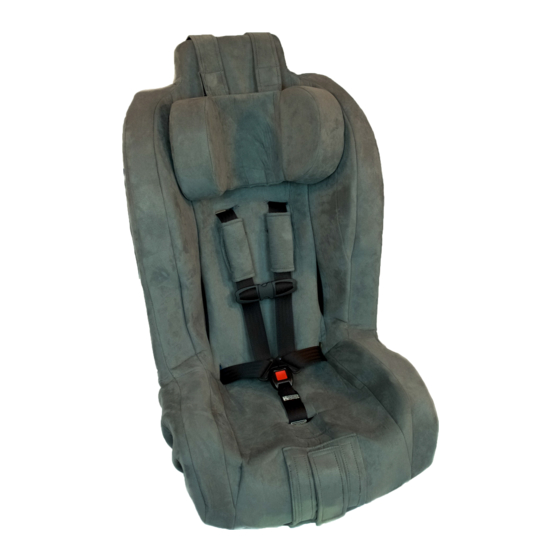
Page 8: Roosevelt Features
Roosevelt Features Head Rest Cover Harness Neck Pads Slot Chest Clip Seat belt Harness Slot Harness Adjuster Buckle Harness Adjuster Flap Harness Adjuster Strap Page 8... - Page 9 Roosevelt Features, Continued Head Rest EZ-Tether Attachment Connector Strap Strap Anchor Tether Assembly Harness Harness Slot Cover Tilt Bar Attachment Flap Splitter Plate Harness Anchor Lower Anchor Adjuster Buckle Anchor Lower Anchor Hook Harness Adjuster Strap Page 9...
-
Page 10: Additional Parts
Additional Parts Side Support Foam Pieces (Page 14) Pommel (Page 17) Head Rest (Page 15) Neck Pads (Page 8) Bobbie Pin (Page 51) Locking Clip (Pages 26 and 27) Page 10... - Page 11 Additional Parts, Continued 3.5” Seat Extender (Page 16) 2” Seat Extender (Page 16) Tilt Bar (Page 13) EZ-Tether Connector Strap (Pages 30-33) Tether Assemblies (Pages 12, 42, 43) Page 11...
-
Page 12: Attaching The Tether To The Restraint
Attaching the Tether to the Restraint 1. Remove the top of the cover and foam from the restraint (Figure A). 2. Remove a tether assembly from the hardware bag. Note: Figures B-F show the back of the restraint. 3. From the back of the re- straint, insert the looped end of the tether assembly through one of the vertical... -
Page 13: Tilt Bar Installation
Tilt Bar Installation Warning: This restraint must be used · with the tilt bar for children weighing 65 lbs. or less. Its use is optional for children weighing more than 65 lbs. 1. Obtain a soft mallet or hammer and piece of wood (Figure A). 2. -
Page 14: Installation Of Positioning Devices
Installation of Positioning Devices Side Support Foam Installation 1. Detach the plastic hook and the cover flap on one side of the cover as shown in Steps 1 and 2 on Page 2. Partially remove one side of the cover (Figure A). 3. -
Page 15: Headrest Installation
Installation of Positioning Devices, Continued Headrest Installation 1. Lay the headrest against the front sur- face of the restraint with it’s attachment straps resting across the top of the re- straint (Figure A). 2. Route one of the attachment straps over the top of the restraint, down the backside and... -
Page 16: Seat Extender Installation
Installation of Positioning Devices, Continued Seat Extender Installation Note: If your child’s knees extend past the edge of the restraint’s seating surface, then you can use one of the seat extenders to improve comfort. 1. Partially remove the fabric cover from the front edge of the restraint (Figure A). -
Page 17: Pommel (Abductor) Installation
Installation of Positioning Devices, Continued Pommel (Abductor) Installation Note: The pommel foam may be removed from its fabric covering (see hook/loop flap on bottom) and the foam may be “cut down” to accommodate the oc- cupant. 1. Attach the pommel to the buckle webbing by routing the strap (See arrow, Figure A) -
Page 18: Adjusting Harness Height
Adjusting Harness Height 1. Place the restraint on the floor and lean the back of it against a secure surface. Loosen the harness by lifting the harness adjuster (See Ar- row, Figure A) and pulling the top of both harness straps forward (Figure A). - Page 19 Adjusting Harness Height, Continued 8. Remove one of the har- ness straps from the split- ter plate (Figure E) and pull it through the har- ness slot to the front side of the restraint (Figure F). 9. Insert the harness strap through the appropriate slot (Figure G) and pull it through to the back side...
-
Page 20: Adjusting The Buckle
Adjusting the Buckle Note: Figure A shows the Buckle Position 1 bottom side of the re- Anchor straint. Note: This child restraint has two buckle positions. Position 2 (See Figure A) must not be used by chil- dren weighing 65 lbs. or Position 2 less. - Page 21 Adjusting the Buckle, Continued 4. Pull the buckle anchor through the slot in the plastic shell to the front Position 1 side of the restraint as shown in Figure D (With the fabric cover removed for clarity). 5. Continue to pull the buckle anchor through the fabric cover (Figure E).
- Page 22 Adjusting the Buckle, Continued 7. Insert the buckle anchor through the slot in the plastic shell for position 2 (See arrow, Figure G). The fabric cover is Position 2 removed for clarity. 8. Pull the buckle anchor through the slot in the plastic shell and out of the bottom side of the restraint (Figure 9.
-
Page 23: Securing The Harness Prior To Installation
Securing the Harness Prior to Installation Note: Prior to installing the restraint, please perform the following steps to ensure the safety of your child. 1. Place the restraint on the floor and lean the back of it against a secure surface. 2. - Page 24 Locking the Lap-Shoulder Belt Note: Pages 25-29 describe how to lock a lap-shoulder belt. First, install the restraint using one of the installation methods described on pages 30-41. If you used a lap-shoulder belt to install the restraint, then return to this section to determine how to lock it. The three options discussed on ·...
-
Page 25: Locking The Lap-Shoulder Belt
Locking the Lap-Shoulder Belt, Continued Option 1—Locking Latch Plate If your owner’s manual indicates that the vehicle seat belt is · equipped with a locking latch plate, then lock the restraint according to the following steps: 1. While pressing down with your knee, remove slack from the lap belt portion of the lap-... -
Page 26: Option 2- Emergency Locking Retractor
Locking the Lap-Shoulder Belt, Continued Option 2—Emergency Locking Retractor (ELR) If your owner’s manual indicates that the vehicle seat belt · is equipped with an emergency locking retractor (ELR), then you must use a locking clip as specified below. 1. After buckling the safety belt, press your knee firmly into the restraint... - Page 27 Locking the Lap-Shoulder Belt, Continued Option 2—Emergency Locking Retractor (ELR), Continued 4. While keeping the seat belt in the restraint’s belt path and continuing to pinch the belts together, thread both portions of the vehicle seat belt into the locking clip (Figures DL, DS and EL, ES).
-
Page 28: Option 3-Switchable Retractor
Locking the Lap-Shoulder Belt, Continued Option 3—Switchable Retractor 1. If your owner’s manual indicates that the vehicle seat belt is equipped with a switchable retrac- tor, then engage the retractor as specified in the manual. Usually this is done by slowly pulling the shoulder portion all the way out... -
Page 29: Checking The Stability Of The Restraint
Locking the Lap-Shoulder Belt, Continued Option 3—Switchable Retractor, Continued 3. While still pressing down with your knee, remove slack from the shoulder belt portion of the lap-shoulder belt by pulling up on the upper end of the shoulder por- tion (Figs. CL and CS) and feeding the excess webbing into the retractor... -
Page 30: Lap-Shoulder Belt Installation-Long Route
Lap-Shoulder Belt Installation—Long Route— Preferred Method—Tether Optional Note: The lap-shoulder long belt route is the only installa- tion for which the tether(s) is optional. If the tether (or tethers) are not in use, then they must be removed from the restraint and stored in the trunk, glove box, or inside the house. - Page 31 Lap-Shoulder Belt Installation—Long Route, Contin- 4. Grasp the seat belt and pull it around the side and to the front of the restraint (Figure F). 5. Then insert it, from the front side, through the closest slot, to the backside of the restraint (Figure F).
- Page 32 Lap-Shoulder Belt Installation—Long Route, Contin- 9. Route the free end of the EZ-Tether Connector Strap, which was left hanging in Step 2, over the shoulder portion of the lap- shoulder belt and insert it through the slot in the side wall (Figure J) and secure it on the outside of the restraint (Figure K).
- Page 33 Lap-Shoulder Belt Installation—Long Route, Contin- 11. Remove slack from the shoulder belt portion of the lap-shoulder belt by pulling up on the upper end of the shoulder portion (Figure N) and feeding the excess into the retractor (Figure O). 12. Verify that there is no slack in the seat belt.
-
Page 34: Lap-Shoulder Belt Installation-Short Route
Lap-Shoulder Belt Installation—Short Route— Tether Required 1. Place the restraint on the vehicle seat. Route the tether over the vehicle seatback to avoid “trapping” it be- tween the restraint and vehicle seat (Figure A). 2. Grasp the seat belt and pull it through the nearest belt slot from the back side (Figure B) of the restraint to... - Page 35 Lap-Shoulder Belt Installation—Short Route— Tether Required, Continued 5. Attach the seat belt to the buckle (Figure E). 6. Remove as much slack from the system as possible; first from the lap belt portion by pulling up on the lower end of the shoulder belt portion (Figure F), then from the shoulder belt portion by pulling up on the upper end of the shoulder...
-
Page 36: Lap Belt Installation
Lap Belt Installation—Tether Required 1. Place the restraint on the vehicle seat. Route the tether over the vehicle seatback to avoid “trapping” it between the restraint and vehicle seat (Figure A). 2. Grasp the seat belt and pull it through the nearest belt slot from the back side (Figure B) of the restraint to the front... - Page 37 Lap Belt Installation—Tether Required, Continued 5. Attach the seat belt to the buckle (Figure E). 6. While pressing your knee into the restraint, remove as much slack from the lap belt as possible by pulling the belt’s free end (Figure F). 7.
-
Page 38: Preparing The Latch Assembly For Installation
Preparing the LATCH Assembly for Installation 1. Lay the front of the restraint on a secure surface (Figure A). 2. The restraint is shipped with the LATCH assembly stored through the short belt path (Figure A). 3. Since the LATCH must be used through the long belt path, it is necessary to reroute... - Page 39 Preparing the LATCH Assembly for Installation, Continued 8. Unhook the other end of the LATCH assembly and route it up through the tilt bar and insert it through the nearest seat belt slot (Figure F) and across the back side of the restraint (between the foam and plastic shell) to the slot on the...
-
Page 40: Latch Installation
LATCH Installation—Tether Required WARNING! For children weighing more than 48 pounds, attach the child restraint with the vehicle’s seat belt. Do not use this installation method. 1. Perform the pre- installation steps on pages 38 and 39. 2. Verify that the LATCH assembly is routed as shown in Figures I and J on page 39. - Page 41 LATCH Installation—Tether Required, Continued 6. While placing your knee into the restraint, remove slack from the webbing by pulling the two free ends. (Figure E). 7. Verify that there is no slack in the webbing. If there is any slack, remove it as described in Step 6 and shown in Figure E.
-
Page 42: Attaching The Tether To The Vehicle
Attaching the Tether to the Vehicle Warning: Please review your vehicle owner’s manual carefully to · determine your vehicle’s tether anchor locations. Make sure you attach the tether hook only to a child seat tether anchor. The use of an anchor which is not speci- fied as a child seat tether anchor by your vehicle owner’s manual may result in injury or death to your child in the event of a crash. - Page 43 Attaching the Tether to the Vehicle, Continued 4. Grasp the free end of the webbing and pull it through the adjuster until all of the slack has been removed (Figure D). Note: Both tethers have to be used for children weighing more than 80 lbs.
-
Page 44: Securing Your Child In The Restraint
Securing Your Child in the Restraint 1. Place each of the harness straps to the side to make room for your child (Figure A). 2. Carefully place your child in the restraint with his/ her back positioned against the backrest (Figure B). - Page 45 Securing Your Child in the Restraint, Continued 6. Repeat Step 5 for the other harness strap (Figure E). 7. Fasten the two halves of the chest clip together (Figure F). 8. Remove slack from the lap belt portion of the harness (Figure G).
-
Page 46: Care And Cleaning
Care and Cleaning Cover and Harness Removal 1. Unclip both plastic hooks (one on each side) on the backside of the restraint just below the tilt bar (Figure A). 2. Detach the cover at- tachment flaps (one on each side) on the back- side of the restraint just above the tilt bar (Figure B). - Page 47 Care and Cleaning, Continued Cover and Harness Removal, Continued 6. From the back of the restraint, remove one of the harness straps from the splitter plate (Figure F) and pull it through to the front of the restraint (Figure 7. Repeat Step 6 for the other harness strap.
-
Page 48: Fabric Care
Care and Cleaning, Continued Fabric Care 1. After removal, clean the restraint, pommel, headrest cov- ers and neck pads together (but separate from any other clothing) per Steps 2-4. 2. Machine wash on gentle cycle using mild soap (detergent) with the “wash” and “rinse” cycles set on “cold”. 3. -
Page 49: Cover And Harness Reinstallation
Care and Cleaning, Continued Cover and Harness Reinstallation 1. Place the cover on the restraint. 2. Lay the harness/buckle assembly out on the cover (Figure A). 3. From the front side of the restraint, grasp one of the harness an- chors and twist it so that it can be inserted into its anchor slot... - Page 50 Care and Cleaning, Continued Cover and Harness Reinstallation, Continued through to the back side of the restraint (Figure F). 7. Slide the loop of the harness strap over the splitter plate (Figure G). 8. Repeat Steps 6 and 7 for the other harness strap.
- Page 51 Care and Cleaning, Continued Cover and Harness Reinstallation, Continued 11. Slide the elastic loop (attached to the back side of the cover) over the bobbie pin (found in the parts bag) as shown in Figure K. 12. Then route the elastic loop through the har- ness anchor nearest the plastic hook...
-
Page 52: Limited Warranty
Limited Warranty Merritt Manufacturing, Inc. (Merritt) provides the following limited war ranty on the Roosevelt: Merritt warrants to the original purchaser of the Roosevelt that, if prop erly used strictly in accordance with the instructions and specifications included in the original packaging, it shall be free from defects in ma terials or workmanship for a period of one (1) year from the date of original purchase. Proof of purchase is required, including, but not limited to furnishing to Merritt proof that the owner registration card was returned to Merritt within thirty days of the original purchase or furnishing to Merritt proof of purchase that identifies the claimant as the original purchaser. If any component covered by this warranty fails for reasons covered by this warranty, Merritt will, at its option, provide the original purchaser with repair or replacement components for the covered product or component. This limited warranty is avail able only for purchasers in the United States and Canada. Merritt reserves the right to discontinue or change fabrics, parts, models or products, or to make substitutions. Please note that the upholstery fabric is subject to some degree of wear as a result of normal use. This kind of normal wear is not covered under warranty. To make a claim under this warranty, you must contact Merritt via telephone at (317) 4090148 or write to the company using the ad dress on the back cover of this booklet. PLEASE COMPLETE AND MAIL THE OWNER REGISTRATION CARD WITHIN THIRTY DAYS OF PURCHASE TO PRESERVE YOUR WARRANTY RIGHTS. WARRANTY LIMITATIONS This warranty does not include damages due to external sources, in cluding, but not limited to accident, negligence, misuse, neglect, al teration, repair, improper installation, improper testing or use that is not in conformance with the instructions and specifications in the in struction booklet. LIMITATION OF LIABILITY AND DAMAGES THE WARRANTY AND REMEDIES SET FORTH ABOVE ARE THE SOLE AND EXCLUSIVE REMEDIES AND ARE PROVIDED IN LIEU OF ALL OTHERS, ORAL OR WRITTEN, EXPRESS OR IMPLIED. IN NO EVENT WILL MERRITT, OR THE RETAILER/DISTRIBUTOR SELLING THIS PRODUCT, BE LIABLE TO THE PURCHASER, OR ANY USER OF THIS RESTRAINT OR OTHER THIRD PARTY, FOR ANY DAMAGES; INCLUDING LOST PROFITS, LOST BUSINESS, ... -
Page 53: Warranty
Limited Warranty, Continued AMOUNT OF DAMAGES ABOVE THE AGGREGATE DOLLAR AMOUNT PAID BY THE CUSTOMER FOR THE PURCHASE OF THE PRODUCT COVERED BY THIS WARRANTY. LIMITATIONS OF WARRANTIES AND OTHER WARRANTY TERMS AND STATES’ LAW MERRITT FULLY DISCLAIMS AND MAKES NO IMPLIED WARRAN TIES OF ANY KIND, INCLUDING, BUT NOT LIMITED TO IMPLIED WARRANTIES OF MERCHANTABILITY AND FITNESS FOR A PAR TICULAR USE, AND MAKES NO EXPRESS WARRANTIES BE YOND THOSE STATED HERE. NOTWISTHSTANDING THE FORE GOING, IF ANY IMPLIED WARRANTIES ARE DEEMED TO BE GIVEN BECAUSE THE APPLICABLE LAW PROHIHBITS THEIR EXCLUSION, THEN ANY SUCH IMPLIED WARRANTIES, INCLUD ING IMPLIED WARRANTIES OF MERCHANTABILITY AND FIT NESS FOR A PARTICULAR PURPOSE, SHALL BE LIMITED TO THE DURATION AND TERMS OF THE EXPRESS WRITTEN WAR RANTY. SOME STATES DO NOT ALLOW THE LIMITATION OF IM PLIED WARRANTIES, LIMITATIONS ON HOW LONG AN IMPLIED WARRANTY LASTS OR THE EXCLUSION OR LIMITATION OF IN CIDENTAL OR CONSEQUENTIAL DAMAGES. THEREFORE, IN THOSE STATES, THE LIMITATIONS LISTED ABOVE MAY NOT APPLY TO YOU. THIS WARRANTY AFFORDS YOU WITH SPE CIFIC LEGAL RIGHTS AND YOU MAY HAVE ADDITIONAL RIGHTS, DEPENDING ON THE STATE IN WHICH YOU RESIDE. BINDING ARBITRATION Any dispute, controversy or claim (whether in contract, tort or other wise, whether preexisting, present or future, and including statutory, common law, intentional torts and equitable claims) against Merritt, its agents, employees, successors, assigns or affiliates (collectively for purposes of this warranty, “Merritt”), arising from or relating to this warranty and agreement, its interpretation, or the breach, termination or validity thereof, the relationships which result from this warranty and agreement (including, to the full extent permitted by applicable law, relationships with third parties who are not parties to this warranty and agreement), SHALL BE RESOLVED EXCLUSIVELY AND FI NALLY BY BINDING ARBITRATION ADMINISTERED BY THE AMERICAN ARBITRATION ASSOCIATION under its code of proce ... -
Page 54: Revision History
Revision History Revision 0; September, 2007 - Original Version Revision 1; March, 2008 Notable Changes: Use of the tilt bar is now optional for occupants · weighing more than 65 lbs. (Pages 4, 13). The pommel foam may be removed from its fabric ·... - Page 55 Page Intentionally Left Blank Page 55...
- Page 56 The Roosevelt Merritt Manufacturing, Inc. P.O. Box 17152 Indianapolis, IN 46217-0152 Phone: 317-409-0148 Fax: 317-893-2567 www.eztether.com E-Mail: info@eztether.com Revision 1; March, 2008...
Need help?
Do you have a question about the Roosevelt and is the answer not in the manual?
Questions and answers
How do i remove the tilt Bar on the Roosevelt car seat?