
Related Manuals for SYNERGY SYSTEMS SynPaQ/E

Summary of Contents for SYNERGY SYSTEMS SynPaQ/E
-
Page 1: Gps Sensor
SynPaQ/E GPS Sensor USER’S GUIDE 9950 Scripps Lake Dr. Suite #106 San Diego, Ca. 92131 TEL: 858.566.0666 FAX: 858.566.0768 Internet: http://www.synergy-gps.com E-Mail: OEMTECH@synergy-gps.com... -
Page 2: Gps Performance
U.S. Department of Defense and is made available for civilian use solely at its discretion. The GPS is subject to degradation of position and velocity accuracies by the Department of Defense. Synergy Systems does not warrant or control GPS availability or performance. Copyright 1998—2012 Synergy Systems, LLC... -
Page 3: Product Description
1994 and 2002. The special DB-9 I/O wiring has been retained for backward compatibility for Motorola LMPS and many other customers. This version of the SynPaQ/E uses a BNC for the GPS antenna connector. With the increased convenience of using a DB-9 connector, there is a resultant drop in water and dust resistance. - Page 4 PHYSICAL CHARACTERISTICS Size: Less connectors and mounting plate. 3.22” W x 5.21”L x 1.26”H 82mm x 132mm x 32mm Weight: 10 oz (0.28 kg) Housing: Black Powder-Coated Aluminum ELECTRICAL INTERFACE (Standard) Power/Data: SwitchCraft EN3P8M - 8 Pin Mating Conn: SwitchCraft EN3C8F - 8 Pin GPS Antenna: TNC Jack (Others optional) ELECTRICAL INTERFACE (XTS)
- Page 5 Repeated opening of this device under conditions of proper input power indicate a probable internal problem, and the SynPaQ/E should be returned to Synergy Systems for repair.
-
Page 6: Front Panel Indicators
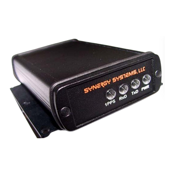
FRONT PANEL INDICATORS The front panel of the SynPaQ/E contains four LEDs for status display. Details are as follows: PWR—This LED should always be GREEN when power is applied to the SynPaQ/E. TxD—The TxD indicator provides the user with visual feedback concerning data output from the receiver. -
Page 7: Rear Panel Connectors
REAR PANEL CONNECTORS Standard Interface The rear panel of the Standard SynPaQ/E contains both a TNC connector for antenna connection and an 8 pin combination Power/Data connector. Pin functions are as follows: FUNCTION 1PPS Out, TTL levels Commands In, RS-232 levels... - Page 8 “XTS” Interface Emulating the original Motorola XT Oncore The “XTS” version of the SynPaQ/E uses a standard DB-9M connector for data and power. This is NOT a standard DB-9 serial interface (Do not use RS-232 port isolators) Pin functions are as follows:...
-
Page 9: Usb Interface
USB Interface The “USB” version of the SynPaQ/E uses a standard USB Type B connector for data and power. Pin functions are as follows: FUNCTION Red: +5V / Voltage + / VCC White: D - / Data - / USB -... -
Page 10: Antenna Installation
SYNPAQ/E OPERATION With power applied, the SynPaQ/E is ready for immediate operation. Communications with the unit may be established with windows based GPS programs, the SW included with the kit is dependent on the receiver ordered with the SynPaQ/E. Communication SW may also be downloaded from Synergy’s website at www.synergy-...
Need help?
Do you have a question about the SynPaQ/E and is the answer not in the manual?
Questions and answers