Samsung GX-10 Service Manual
Hide thumbs
Also See for GX-10:
- User manual (262 pages) ,
- Manual de usuario (258 pages) ,
- Brochure & specs (24 pages)
Table of Contents
Advertisement
Advertisement
Table of Contents

Related Manuals for Samsung GX-10


Summary of Contents for Samsung GX-10
-
Page 2: Table Of Contents
6. Viewfinder Indications ………………………………………………………………………………………… 19 7. LCD Panel Indications ………………………………………………………………………………………… 21 Ⅱ. EXPLODED VIEW AND PARTS LIST 1. GX-10 : FIG. 1 ………………………………………………………………………………………………… 22 2. GX-10 : FIG. 2 ………………………………………………………………………………………………… 23 3. GX-10 : FIG. 3 ………………………………………………………………………………………………… 24 4. GX-10 : FIG. 4 ………………………………………………………………………………………………… 25 PARST LIST FOR GX-10_CODE…………………………………………………………………………... - Page 3 2. Adjustments by menus 1) Preparing the adjustment…………………………………………………………………………………… 54 2) Adjustment process………………………………………………………………………………………… 60 . OPS Unit Adjustment ………………………………………………………………………………… 62 . Adjustment of the Single Reflex part ………………………………………………………………… 67 1. BV adjust (brightness value) ………………………………………………………………………… 73 2. AF adjustment………………………………………………………………………………………… 83 3. Focus adjustment…………………………………………………………………………………… 105 4.
-
Page 4: Specification
Ⅰ. SPECIFICATION 1. SPECIFICATION Image Sensor - Type : 23.5mm×15.7mmCCD - Effective Pixel : Approx. 10.20 Mega-pixel - Total Pixel : Approx. 10.75 Mega-pixel Lens - Mount : PENTAX K bayonet mount - Usable Lens : Schneider D-XENON, D-XENOGON Lens * All PENTAX DSLR lenses are available. - Page 5 10M : Super Fine 104 Fine 178 Normal 306 6M : Super Fine 174 Fine 297 Normal 512 2M : Super Fine 474 Fine 802 Normal 1360 ※ These figures are measured under Samsung’s standard conditions and may vary depending on shooting conditions and camera settings.
-
Page 6: System Requirements
Ⅰ. SPECIFICATION 2. System Requirements For Windows For Macintosh PC with processor better than Pentium III 450Mz Power Mac G4 or later (Pentium 700MHz recommended) Windows 2000/ME/XP Mac OS 10.2 or later Minimum 256MB RAM (XP : 512MB) Minimum 256MB RAM 250MB of available hard disk space 250MB of available hard-disk space (1GB recommended) -
Page 7: Names Of Working Parts
Ⅰ. SPECIFICATION 3. Names of Working Parts Front Flash ( pop-up button Front e-dial RAW button Lens mount index Mirror AF coupler Self-Timer lamp / Remote control receiver Focus mode lever Lens unlock button Lens information contacts Back Exposure Compensation ( ) / LCD panel lamp button Self-Timer lamp / Remote control receiver Rear e-dial... - Page 8 Ⅰ. SPECIFICATION Front e-dial Built-in Flash Main Switch Metering Lever Shutter Button Green button Mode dial Strap Strap LCD panel Dioptre adjustment lever Rear e-dial Hot shoe Side Connection ports Memory Card Slot Cable switch port Terminal Cover Card cover Memory Card Slot USB / Video...
- Page 9 Ⅰ. SPECIFICATION Bottom Battery cover & Tripod socket Lock lever Battery Chamber Battery Chamber cover Battery Chamber Battery Holder...
-
Page 10: Using The Button Functions
Ⅰ. SPECIFICATION 4. Using the Button Functions Capture Mode ■ Functions of buttons used during shooting. ① ⑥ ② ⑤ ④ ③ ① Shutter release button Press to capture images. ② Main switch Move to turn the power on/off and confirm the depth of field (Preview) ③... - Page 11 Ⅰ. SPECIFICATION ⑫ ① ⑪ ⑩ ② ⑨ ⑧ ③ ⑦ ④ ⑥ ⑤ ① Exposure bracket button Sets the Exposure bracket. ② MENU button Displays the [CAPTURE MENU], [CUSTOM1 MENU], [CUSTOM2 MENU], [SETUP MENU] and [PLAYBACK MENU] menu. ③ INFO butto Press to show shooting information on the LCD monitor.
- Page 12 Ⅰ. SPECIFICATION ⑤ ① ④ ② ③ ① Metering mode lever Changes the metering modes. ② Mode dial Changes the camera modes. ③ Rear e-dial Sets aperture ISO sensitivity values. ④ Green button Resets exposure settings and automatically adjusts the appropriate exposure in a M (Manual) mode.
- Page 13 Ⅰ. SPECIFICATION Playback mode ■ Functions of buttons used during playback. ① ② ③ ④ ① Front e-dial Use it to display the previous or next image in magnified playback or adjust the digital filter. ② Main switch Move to turn the camera on and off. ③...
- Page 14 Ⅰ. SPECIFICATION ⑧ ① ② ⑦ ③ ⑥ ④ ⑤ ① MENU button Press to display the [CAPTURE MENU], [PLAYBACK MENU], [CUSTOM1 MENU], [CUSTOM2 MENU] and [SETUP MENU] menu. ② button Press to delete images. ③ INFO button Press to show shooting information on the LCD monitor. ④...
-
Page 15: Lcd Monitor Indications
Ⅰ. SPECIFICATION 5. LCD Monitor Indications ■ The following indicators appear on the LCD monitor depending on the status of the camera. LCD monitor While Power is On or Operating Mode Dial ■ Guides appear on the LCD monitor for 3 seconds when powered on or setting dial mode. INFORMATION ●... - Page 16 Ⅰ. SPECIFICATION Capture Mode ■ Press the INFO button in capture mode to display the capture function settings on the LCD monitor for 15 seconds. Detailed Information 1. Shooting mode 17. BA compensation value 2. Custom mode 18. Colour space 3.
- Page 17 Ⅰ. SPECIFICATION Playback Mode ■ Press the INFO button in playback mode to display the image information on the LCD monitor. Whenever pressing the INFO button, Basic information, Histogram, Detail information and no information will display in that order. INFORMATION ●...
- Page 18 Ⅰ. SPECIFICATION Histogram Display ■ Brightness Histogram that distributes brightness of the image and RGB Histogram that distributes colour of the image are selectable by using the Up and Down (▲, ▼) button. [Playback] [Y Histogram] [RGB Histogram] 1. Capture quality (Image file type) 6.
-
Page 19: Viewfinder Indications
Ⅰ. SPECIFICATION 6. Viewfinder Indications 1. Autofocus frame 2. Spot metering frame 3. Focus point indicator : Blinks when OPS is operating 5. Flash status : Appears when flash is available and blinks when flash is recommended but not set. 6. - Page 20 Ⅰ. SPECIFICATION 11. EV compensation : Appears when EV compensation is available or in use. 12. Flash Exposure Compensation : Appears when Flash Exposure is compensated. 13. AE Lock indicator : Appears when AE is locked. 14. ISO sensitivity warning : Appears when warning value is exceeded.
-
Page 21: Lcd Panel Indications
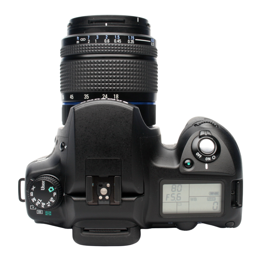
Ⅰ. SPECIFICATION 7. LCD Panel Indications ■ The following information appears in the LCD panel on top of the camera. 1. Shutter speed 5. Exposure Bar 2. Aperture 6. Auto Bracket 3. Flash mode 7. Flash Exposure Compensation indicator : Built-in flash is ready (when blinking, 8. -
Page 22: Ⅱ. Exploded View And Parts List
Ⅱ. EXPLODED VIEW AND PART LIST 1. GX-10 : FIG. 1... -
Page 23: Gx-10 : Fig.
Ⅱ. EXPLODED VIEW AND PART LIST 2. GX-10 : FIG. 2... -
Page 24: Gx-10 : Fig.
Ⅱ. EXPLODED VIEW AND PART LIST 3. GX-10 : FIG. 3... -
Page 25: Gx-10 : Fig.
Ⅱ. EXPLODED VIEW AND PART LIST 4. GX-10 : FIG. 4... -
Page 26: Parst List For Gx-10_Code
Ⅱ. EXPLODED VIEW AND PART LIST ▶ PARTS LIST FOR GX-10_CODE Fig. No. Parts No. Parts Name Q'ty Location O-A3 Q8100046101A BOTTOM_PLATE_ASSY Q8100046201A RIGHT_FRONT_PLATE Q8100046301A RIGHT_SHOULDER_PLATE Q8100046401A LEFT_SHOULDER_PLATE Q8100046501A BATTERY_CASE_COVER Q8100046601A BATTERY_CONTACT_A Q8100046701A STRAP_HOOK_PLATE_R Q8100046801A STRAP_HOOK_PLATE_L Q8100046901A HOOK Q8100047001A HOOK_SPRING Q8100047101A STIMULATE_SPRING Q8100047201A... - Page 27 Ⅱ. 설치 & FAQ ▶ PARTS LIST FOR GX-10_CODE Fig. No. Parts No. Parts Name Q'ty Location A164 Q8100049501A NAME_PLATE A165 Q8100049601A AF_MODE_CHANGEOVER_RING_LEVER O-A166 Q8100049701A AF_MODE_CLICK_PLATE A168 Q8100049801A O-RING_6X1 A169 Q8100049901A RAW_BUTTON A171 Q8100050001A SCREW_C A172 Q8100050101A SCREW A174 Q8100050201A RETAINER_SCREW_C 2H4, 2H5 A175...
- Page 28 Ⅱ. EXPLODED VIEW AND PART LIST ▶ PARTS LIST FOR GX-10_CODE Fig. No. Parts No. Parts Name Q'ty Location A251 Q8100052701A FOCUS_POINT_SELECT_DIAL A252 Q8100052801A BEARING_PLATE O-A253 Q8100052901A BRUSH_ASSY A255 Q8100053001A 4WAY_CONTROL_KEY A256 Q8100053101A LEVER_CLICK_SPRING A257 Q8100053201A OK_BUTTON A258 Q8100053301A RUBBER_SHEET_A A259 Q8100053401A LINING_BOARD_A...
- Page 29 Ⅱ. EXPLODED VIEW AND PART LIST ▶ PARTS LIST FOR GX-10_CODE Fig. No. Parts No. Parts Name Q'ty Location A303 Q8100056201A LCD_WINDOW_D-S_TAPE A304 Q8100056301A O-RING_1.5X0.5 A310 Q8100056401A PVF_TAPE_2X3 A311 Q8100056501A MAIN_SW_LEVER A312 Q6107071901A MAIN_SW_CLICK_SPRING A313 Q6107072001A MAIN_SW_LEVER_SPRING A314 Q8100056601A MAIN_SW_BRUSH O-A316 Q9007263601A RELEASE_BUTTON_ASSY...
- Page 30 Ⅱ. EXPLODED VIEW AND PART LIST ▶ PARTS LIST FOR GX-10_CODE Fig. No. Parts No. Parts Name Q'ty Location A354 Q8100058801A DIAL_CLICK_SPRING 4C3, 4E1 A355 Q8100058901A DIAL_WATERPROOF_SHEET_D O-A362 Q8100059001A FLASH_ARM_ASSY A363 Q8100059101A ARM_RETAINER O-A365 Q8100059201A FLASH_HOOK_LEVER_ASSY A366 Q8100059301A FLASH_HOOK_LEVER_CASE A367 Q8100059401A FLASH_HOOK_SPRING A368...
- Page 31 Ⅱ. EXPLODED VIEW AND PART LIST ▶ PARTS LIST FOR GX-10_CODE Fig. No. Parts No. Parts Name Q'ty Location A456 Q8100062101A WATERPROOF_SHEET_1.2X11 A457 Q8100062201A WATERPROOF_SHEET_1.2X20 A461 Q8100062301A WATERPROOF_SHEET_1.2X158 A463 Q8100062401A WATERPROOF_SHEET_1.5X34 2C6, 3C7 A464 Q8100062501A WATERPROOF_SHEET_1.2X96 2B5, 2E4 A471 Q8100062601A WATERPROOF_SHEET_1.5X25 A472 Q8100062701A...
- Page 32 Ⅱ. EXPLODED VIEW AND PART LIST ▶ PARTS LIST FOR GX-10_CODE Fig. No. Parts No. Parts Name Q'ty Location M318 Q8100065001A LIGHT_SEAL_FRAME_C N300 Q8100065101A PIEZO-ELECTRIC_BUZZER O-O170 Q8100065201A SI_BLOCK O201 Q8100065301A LCD_PANEL O202 Q8100065401A LCD_FLAME O203 Q8100065501A LCD_RETAINER O204 Q8100065601A CONDUCTIVE_RUBBER O207 Q8100065701A MAIN_SW_ADHESIVE_TAPE...
- Page 33 Ⅱ. EXPLODED VIEW AND PART LIST ▶ PARTS LIST FOR GX-10_CODE Fig. No. Parts No. Parts Name Q'ty Location Q8100068501A COPPER_FOIL_TAPE 1E4, 1F5 O-T100 Q8100068601A MAIN_P.C.BOARD O-T700 Q8100068701A UPPER_FLEX_CIRCUIT-A O-T750 Q8100068801A UPPER_FLEX_CIRCUIT-B O-T770 Q8100068901A PZ_P.C_BOARD T901 Q8100069001A LOWER_F.P_C.BOARD O-T903 Q8100069101A SWITCH SHEET_A O-T904 Q8100069201A...
- Page 34 Ⅱ. EXPLODED VIEW AND PART LIST ▶ PARTS LIST FOR GX-10_CODE Fig. No. Parts No. Parts Name Q'ty Location Q8100071801A CNL-D_1.7X2.5 4C3, 4D6, 4E7, 4F3, 4F5, 4G3, 4H4 Q8100071901A CNL-D_1.7X3.0 1H5, 3C6, 3D7, 4D2 Q8100072001A CNL-D_1.7X4.0 1G6, 4G7 Q8100072101A CNL-D_1.7X5.5 Q8100072201A CNL-E_1.7X2.2 Q8100072301A...
- Page 35 Ⅱ. EXPLODED VIEW AND PART LIST ▶ PARTS LIST FOR GX-10_CODE Fig. No. Parts No. Parts Name Q'ty Location DT10 Q8100075301A DOUBLE_STICK_TAPE_4X4 DT11 Q8100075401A DOUBLE_STICK_TAPE_4X6 1H3, 2D2 DT12 Q8100075501A DOUBLE_STICK_TAPE_4X10 1G3, 4E2 DT13 Q8100075601A DOUBLE_STICK_TAPE_4X15 1H4, 4D6 DT14 Q8100075701A DOUBLE_STICK_TAPE_4X25 DT15 Q8100075801A DOUBLE_STICK_TAPE_5X5...
-
Page 36: Packing Item_Parst List For Gx-10_Code
Ⅱ. EXPLODED VIEW AND PART LIST ▶ PACKING ITEM_PARTS LIST FOR GX-10_CODE Part No Part Name Q'ty Remark Q9001121501A BODY Q4609016301A DIGIMAX MASTER_RAW CONVERTER_GX-10 Q3801000701A AC CODE CABLE_KOR-D1 Q3801000901A AC CODE CABLE_EXP-D1 Q3801000801A AC CODE CABLE_USA-D1 Q3801001001A AC CODE CABLE_UK-DSC220SE Q3801001101B AC CODE CABLE_AUS-D1 Q3801003701A... -
Page 37: Ⅲ. Adjustment
Ⅲ. ADJUSTMENT 1. Firmware 1) Checking the general Firmware version 1. Turn off the camera. 2. Press and hold the MENU button and turn on the camera. 3. The firmware version displays on the LCD monitor. -
Page 38: Checking The Full Firmware Version
Ⅲ. ADJUSTMENT 2) Checking the Full Firmware version 1. Turn off the camera. 2. Download the Full Firmware and save it on an SD card (Root directory). ※ Move the cursor on the program download button and click the right mouse button. And then select "Save as (A)..."... - Page 39 Ⅲ. ADJUSTMENT 4. Turn on the camera. 5. The firmware version displays on the LCD monitor.
-
Page 40: Upgrading The Firmware Of Camera User
Ⅲ. ADJUSTMENT 3) Upgrading the Firmware of camera user. ※ When you upgrade the firmware, use the AC adapter and Batter at the same time to prevent the camera malfunction. 1. Download the new firmware and save it on an SD card (Root directory). Do not use the Multi Media Card (MMC) when upgrading the firmware. - Page 41 Ⅲ. ADJUSTMENT 5. Press and hold the MENU button and turn on the camera. 6. The following message displays on the LCD monitor. Select [Yes] by using the Up / Down button and press the OK button.
- Page 42 Ⅲ. ADJUSTMENT Upgrading starts. (It may take about 60 second. The processing time depends on the firmware item. *Do not turn off the camera.
- Page 43 Ⅲ. ADJUSTMENT 7. After displaying the [COMPLETE] message, turn off the camera. *After completing the upgrade, the card access lamp (Red) still blinks.
-
Page 44: Upgrading The Firmware Of Service Center
Ⅲ. ADJUSTMENT 4) Upgrading the Firmware of service center 1. Turn off the camera. 2. Download the firmware and save it on an SD card 3. Insert the SD card and do not close the memory card 4. Turn on the camera. Use the AC adapter or fully charged battery. - Page 45 Ⅲ. ADJUSTMENT 5. The following message displays on the LCD monitor. 6. Remove the SD card (Do not close the memory card slot cover.)
- Page 46 Ⅲ. ADJUSTMENT 7. The upgrade starts as shown. Deleting the current firmware..Preparing the new firmware..
- Page 47 Ⅲ. ADJUSTMENT Writing the new firmware..After completing the upgrade, "POWER OFF" message displays. The card access lamp (Red) still blinks. 8. Turn off the camera. FAfter upgrading the firmware, the camera settings are reset to default. (Language, Date, Time) Though the firmware is upgraded, the adjustment data don't be changed.
-
Page 48: How To Upgrade The Firmware After Changing The Main Board
Ⅲ. ADJUSTMENT 5) How to upgrade the firmware after changing the Main board 1. Turn off the camera. 2. Download the firmware and save it on an SD card. 3. Insert the SD card and do not close the memory card slot cover. 4. - Page 49 Ⅲ. ADJUSTMENT 5. The following message displays on the LCD monitor. 6. Remove the SD card and do not close the memory card slot cover.
- Page 50 Ⅲ. ADJUSTMENT 7. The upgrade starts as shown. Deleting the current firmware..Preparing the new firmware..
- Page 51 Ⅲ. ADJUSTMENT Writing the new firmware..After completing the upgrade, "POWER OFF" message displays. The card access lamp (Red) still blinks. 8. Turn off the camera. After upgrading the firmware, the camera settings are reset to default. (Language, Date, Time) Though the firmware is upgraded, the adjustment data don't be changed.
-
Page 52: Run The Eeprom Patch
Ⅲ. ADJUSTMENT 6) Run the EEPROM Patch 1. Turn off the camera. 2. Download 2 files and save them on the SD card. ※ Move the cursor on the program download button and click the right mouse button. And then select "Save as (A)..." to save the file. 3. - Page 53 Ⅲ. ADJUSTMENT 4. Turn on the camera. 5. The "WAIT..." message displays on the LCD monitor. 6. When the "COMPLETE.." message displays on the LCD monitor, turn off the camera.
-
Page 54: Adjustments By Menus
Ⅲ. ADJUSTMENT 2. Adjustments by menus ■ ■ Preparing the adjustment Equipments: □Program for 76832 GX-10 adjustment (Included on the CD-R) □PC for adjustments □SD cards (3EA, over 16MB) □SD card reader or camera with USB cable 1) Preparing SD cards (3EA) for adjustment * Prepare SD cards (3EA) 1. - Page 55 Ⅲ. ADJUSTMENT ① Copy the following files on the CD-R and paste the files on the C: drive. 「76830」 :For Digital adjustment 「76830 SLR」 :For Single Lens Reflex adjustment 「76830 SR Operation Adjustment」 :For SR unit adjustment 「GX10 SR Gain Adjustment」 :For SR gain adjustment 「Initial Data Set」...
- Page 56 Ⅲ. ADJUSTMENT 3) Light source adjustment for digital adjustment Before starting the digital adjustment or when changing the light source, do the light source tuning. Equipment: □K10D Master body for light source tuning (Adoption) □Program for 76830 Digital adjustment □PC with USB port (Windows 2000 or XP) □Luminance box (LB-3300, A light source) □Standard lens for adjustment and F8 set ring ※...
- Page 57 Ⅲ. ADJUSTMENT 3-3. Setup the master body and standard lens ① Set the mode dial to [M] ② Set the focus mode lever to [MF]. ③ Set the OPS lever to [OFF]. ④ Attach the metering standard F8 set ring (for adjustment) on the body. ⑤...
- Page 58 Ⅲ. ADJUSTMENT ⑦ Input the correct Lens ID No. and click the OK button. ⑧ The adjustment program runs and the following menus display.
- Page 59 Ⅲ. ADJUSTMENT ⑨ Click the [Calibration Mode] button.↓ ⑩ Click the [Execute] button. ⑪ After completing the calibration, the following menus display.↓ ⑫ Click the OK button and Quit button to close the program. ⑬ To disconnect the camera from the PC, click the hot plug icon > Reject Hardware > Stop Device and turn off the camera.
-
Page 60: Adjustment Process
■ ■ Adjustment process Adjustment process when the T100 (Main board) is chan The followings are for adjustment items when the T100 Main circuit was changed Blue color texts are only for the GX-10. Changing the T100 [Adjustment] ● Writing the T100 FW when it is changed ●... - Page 61 Ⅲ. ADJUSTMENT Refer to the following menus for each adjustment items Item Link Equipment Remark Exposure BV ADJUST Diaphragm set ring or 50M standard lens EV tester, 50M standard lens, 35-80 lens, Chart for inclination adjustment, AF chart. Adjustment PINT 50M standard lens, AF chart program for Focusing...
-
Page 62: Ops Unit Adjustment
Ⅲ. ADJUSTMENT Ⅰ. OPS Unit Adjustment [Caution 1] When the T100 circuit is changed, this adjustment must be done. [Caution 2] The adjustment must be done in a stable place. Equipment: □SR Unit adjustment program for 76830 □SR Unit table □PC (Windows 2000 or XP with USB port) □USB cable □AC adapter (or DC cord for 76830·DC 8.3V) - Page 63 Ⅲ. ADJUSTMENT 17-2. Preparation ① Set the AF lever to MF. ② Attach the OPS Unit tool to the camera body.(↓) ③ Arrange the camera on a stable table. The lens faces the bottom of the table. ④ When the T100 circuit is changed, check the CCD ID No.. 17-3.
- Page 64 Ⅲ. ADJUSTMENT ⑦ The following menu displays. ⑧ Refer to the following steps. ≪ When the T100 was not changed ≫ Click the [Skip] button...
- Page 65 Ⅲ. ADJUSTMENT ≪ When the T100 was changed ≫ Input the CCD ID No. twice. ↓ Click the [Input] button. ※ If you want to stop the adjustment, click the [Cancel] button. Adjustment is doing..(Adjustment time: About 3Min. 30 Sec.) [Caution] Do not shake the camera during the adjustment.
- Page 66 Ⅲ. ADJUSTMENT ⑨ When the following window displays, the adjustment is complete. ⑩ Check the Unconnect message and click the [X] button to close the window. ※ If the adjustment is NG, the green color will be red.
-
Page 67: Adjustment Of The Single Reflex Part
□FA (F) 35-80mm F4-5.6 lens □Battery adapter for 76830 □Power source (above 8V, 3A) * The process of GX-10 is same with GX-1S (76642) In this chapter, only the rest of GX-10 adjustments are instructed. For more information, refer to each adjustment menus. - Page 68 Ⅲ. ADJUSTMENT 22-1. Compter setup Do the [2. Computer setup > VB runtime setup] first. 22-2. Preparation ① Attach the bottom cover and battery cover on the body (Don't attach the Connection terminal cover) ② Set the Focus mode lever to [MF]. ③...
- Page 69 Ⅲ. ADJUSTMENT ② Do the adjustment as the following steps. Reset the data [Caution] Select [No] button to prevent the SR data deletion. Changing the Main board? ↓ ◇[BV ADJUST] Equipment: □F5.6 iris for the metering standard lens □Metering standard lens and F8 set ring □Light source for AE adjustment (LV 6, 8, 12, 15 or 16, Shutter tester) ①...
- Page 70 Ⅲ. ADJUSTMENT [CCD POSITION ADJUST] adjustment ① Remove the bottom cover. (Don't remove the Power and USB port cover) ② Remove 3 screws. ③ Lift the front cover to the front side and rotate the adjustment screw.
- Page 71 Ⅲ. ADJUSTMENT Equipment: □Battery adapter for 76830 □Power source (Above DC 8V) ① Attach the bottom cover and battery cover to the body. (Don't attach the Connection terminal cover) ② Changing the Select SW, do the adjustment as shown. Battery adapter for 76830...
- Page 72 Ⅲ. ADJUSTMENT 22-5. Closing procedure ① Click the "Cl" button to stop the connection with the camera. (USB close) [Check] Check whether the [Unconnect] message displays on the USB IO ② Click the "end" button to close the window.
-
Page 73: Bv Adjust (Brightness Value)
Ⅲ. ADJUSTMENT 1. BV adjust (brightness value) When taking a picture, selecting the exposure value is one of the important thing. Bright or dark image is decided by the EV. Proper exposure is concluded by the metering sensor. ■ ■ Adjustment procedure ①... - Page 74 Ⅲ. ADJUSTMENT ⑤ Click the "Op" button to connect the camera. Check whether the [Connected] message displays on the USB ⑥ Open the iris and attach the Diaphragm set ring on the camera.
- Page 75 Ⅲ. ADJUSTMENT If there is no Diaphragm set ring tool, any F1.4 lens is available ⑦ Attach the camera on the EV tester.
- Page 76 Ⅲ. ADJUSTMENT ⑧ Click the 2. EXPOSURE ADJUST-BV ADJUST menu Type the Lens ID No. and click the "Input" button.
- Page 77 Ⅲ. ADJUSTMENT ⑨ Select a type of EV tester. ⑩ BClick the BV ADJUST button and a message to set the EV tester to LV6. Set the EV tester to LV6 and click the "OK" button.
- Page 78 Ⅲ. ADJUSTMENT When the following window displays, change the iris to F5.6. Click the "OK" button and the adjustment starts.
- Page 79 Ⅲ. ADJUSTMENT When the "SET LIGHT SOURCE TO LV15. message displays, set the LV to 15 and click the "OK" button. If the adjustment is complete correclty, click the "OK" button.
- Page 80 Ⅲ. ADJUSTMENT The changed data saves on the camera. Click the "CLOSE" buttton.
- Page 81 Ⅲ. ADJUSTMENT ⑪ Click the "Cl" button located on the top side of the Mani menu. Check whether the Connect message changes to Unconnect on the USB IO menu. ⑫ 'Click the "end" button to close the program.
- Page 82 Ⅲ. ADJUSTMENT ⑬ Disconnect the USB cable from the camera and check the metering. 1. Attach the bundle lens to the camera and set camera settings as followings. Camera mode : Av, Aperture : F8, ISO: 200, Metering : Spot, Focus mode : MF, Focal Length : 35m, Focus ring : Infinity.
-
Page 83: Af Adjustment
Ⅲ. ADJUSTMENT 2. AF adjustment 2-1. Adjusting the AF sensor location AF sensor functions as taking an image clearly.Ä When the AF sensor is changed or the sensor malfunctions, do this adjustment. ■ ■ Adjustment process ① Turn off the camera and insert the AC adapter. Connect the camera to the PC with the USB cable. USB port for the camera USB port for the computer (Printer) ②... - Page 84 Ⅲ. ADJUSTMENT ⑤ Click the "Op" button to connect the camera. Check whether the Connect message displays on the USB IO menu. ⑥ Attach the AF sensor inclination adjustment tool (Cross) on the camera. Set the focus mode to MF.
- Page 85 Ⅲ. ADJUSTMENT ⑦ Put the camera (with the Cross) on the EV tester. ⑧ Click the 3.AF AND REL ADJ - CCD POSITION ADJ - ADJUSTMENT button.
- Page 86 Ⅲ. ADJUSTMENT ⑨ Click the "DumpStart" button on the Alpha-CROSS menu tab. Set the EV tester to LV12 and click the "OK" button.
- Page 87 Ⅲ. ADJUSTMENT If the result displays as green color, it is correct. If the result displays as red color, adjust the AF sensor inclination by rotaing the two hexagon screws until the color comes to be green.
- Page 88 Ⅲ. ADJUSTMENT ⑩ Attach the AF sensor inclination tool (Square) on the camera. Set the focus mode to MF.
- Page 89 Ⅲ. ADJUSTMENT Click the "DumpStart" button on the Beta-SQUARE menu tab. Set the EV tester to LV12 and click the "OK" button.
- Page 90 Ⅲ. ADJUSTMENT If the result is green, it is correct. If the result displays as red color, adjust the AF sensor inclination by rotaing the two hexagon screws until the color comes to be green.
- Page 91 Ⅲ. ADJUSTMENT ⑪ Attach the standard lens (50M, F1.4) on the camera. Prepare the No.1 AF chart. Keep the distance between the chart and camera mount to 1,954.5mm. Use the tripod. The distance between the chart and camera is 1.9545m...
- Page 92 Ⅲ. ADJUSTMENT Click the "Start" button on the Fucos menu tab. Check the conditions and click the "OK" button.
- Page 93 Ⅲ. ADJUSTMENT Set the centers of the blue graphs of the 3 part (Left, Center, Right) on the standard line (Red color). Move the camera mounted on the tirpod slightly to the left or right directions to match the center of the graphs (Red color, bottom of the curved graph).
- Page 94 Ⅲ. ADJUSTMENT If the result displays as red color, adjust the AF sensor inclination by rotaing the three hexagon screws until it comes to be green. rotate the screws same times. If the screws are rotated differently, the inclination is changed and you must check the inclination or ajust the camera again.
- Page 95 Ⅲ. ADJUSTMENT 2-2. Checking the AF sensor position This chapter is for checking the AF sensor position after the general AF sensor adjustments. ■ ■ Checking process ① Attach the 35-80 F4-5.6 lens on the camera. If the 35-80 F4-5.6 lens is not prepared, the bundle lens is available. When the bundle lens is used, set the camera as followins.
- Page 96 Ⅲ. ADJUSTMENT ② Attach the camera (Mounted 35-80 or bundle lens) on the EV tester. ③ Click the 3. AF AND REL ADJ - CCD POSITION ADJ - POSITION CHECK button.
- Page 97 Ⅲ. ADJUSTMENT ④ Set the EV tester to LV12. If the 35-80 lens is mounted, set the lens as 80mm and 0.4M distance ring and click the 'CHECK' button. If the bundle lens is mounted, set the lens as 55mm and 0.4M distance ring. ⑤...
- Page 98 Ⅲ. ADJUSTMENT Click the 'CLOSE' button to close the AF sensor postion check window.
- Page 99 Ⅲ. ADJUSTMENT If the Diaphragm set ring is not prepared, a lens that has F1.4 is available. ② Attach the 50M lens mounted camera on the EV tester.
- Page 100 Ⅲ. ADJUSTMENT ③ Click the 3. AF ADN REL ADJ - AGC LEVEL ADJUST button. ④ Select a EV tester type and click 'AGC Adust' button to adjust the LV. Select the 6, 7, 12, 15 in order. After completing the adjustment, click the "Close" button to close the window.
- Page 101 Ⅲ. ADJUSTMENT 2-4. Uniformity adjust: Adjustment for each AF sensors output equality Each AF sensors output are not equal. Be equal each AF sensors output and the AF sensors performance are improved. When the AF sensor is changed or AF sensor has malfunction, do this adjustment. ■...
- Page 102 Ⅲ. ADJUSTMENT ③ Click the 3. AF AND REL ADJ - UNIFORMITY ADJUST button. ④ Set the distance of Macro 50mm lens to infinity and the EV tester to LV12. Click the 'Adjust' button to start the adjustment.
- Page 103 Ⅲ. ADJUSTMENT If the result is green, the adjustment is complete. Click the 'Close' button to stop the adjustment. ⑤ Click the 'Cl' button on the top of the main menu. Check whether the Connect message is changed to Unconnect on the USB IO menu.
- Page 104 Ⅲ. ADJUSTMENT ⑥ Click the 'end' button to close the program.
-
Page 105: Focus Adjustment
Ⅲ. ADJUSTMENT 3. Focus adjustment 3-1. TEMP ADJUSTMENT: Temperature setting for the Focus adjustment This adjustment is for inputing the temperature of the test room. Generally, you can input the proper temperature, but if a specified temperature is required, put the exact temperature. ■... - Page 106 Ⅲ. ADJUSTMENT ⑤ Click the "Op" button to connect the camera. Check whether the Connected message displays on the USB IO menu. ⑥ Click the 3. AF AND REL ADJ - FOCUS OFFSET ADJUST - TEMP ADJ button.
- Page 107 Ⅲ. ADJUSTMENT ⑦ Set the focus mode to MF and select the temperature unit (1). Input the test room temperature and click the 'Temp Adjust' button. The temperature is adjusted. Click the 'OK' button.
- Page 108 Ⅲ. ADJUSTMENT The temperature is saved on the camera. After saving the temperature, click the 'Close' button to close the window.
- Page 109 Ⅲ. ADJUSTMENT 3-2. HORIZONTAL focus adjustment ■ ■ Adjustment process ① Attach the standard lens (50M, F1.4) on the camera. Prepare the No.1 AF chart for horizontal focus. Keep the distance between the chart and camera mount to 1,954.5mm. Use the tripod. The distance between the chart and camera is 1.9545m...
- Page 110 Ⅲ. ADJUSTMENT ② Click the 3. AF AND REL ADJ - FOCUS OFFSET ADJUST - HORIZONTAL button. “OK” 를 클릭해 조정한다. ③ Check the settings of the message and click the 'OK' button.
- Page 111 Ⅲ. ADJUSTMENT Click the 'START' button. Set the centers of the blue graphs of the 3 part (Left, Center, Right) on the standard line (Red color). Move the camera mounted on the tirpod slightly to the left or right directions to match the center of the graphs (Red color, bottom of the curved graph).
- Page 112 Ⅲ. ADJUSTMENT When the centers are matched, click the "ADJUST" button. If the centers can't be matched, match the centeral part of the graph. The adjustment is complete. Click the 'OK' button.
- Page 113 Ⅲ. ADJUSTMENT Click the 'Close' button to close the window.
- Page 114 Ⅲ. ADJUSTMENT 3-3. VERTICAL focus adjustment ■ ■ Adjustment process ① Attach the standard lens (50M, F1.4) on the camera. Prepare the No.2 AF chart for vertical focus. Keep the distance between the chart and camera mount to 1,954.5mm. Use the tripod. The distance between the chart and camera is 1.9545m...
- Page 115 Ⅲ. ADJUSTMENT ② Click the 3. AF AND REL ADJ - FOCUS OFFSET ADJUST - VERTICAL button. ③ Check the message and click the 'OK' button.
- Page 116 Ⅲ. ADJUSTMENT Click the 'START' button. Set the centers of the blue graphs of the 3 part (Left, Center, Right) on the standard line (Red color). Move the camera mounted on the tirpod slightly to the left or right directions to match the center of the graphs.
- Page 117 Ⅲ. ADJUSTMENT When the centers are matched, click the "ADJUST" button. If the centers can't be matched, match the centeral part of the graph. The adjustment is complete. Click the 'OK' button.
- Page 118 Ⅲ. ADJUSTMENT Click the 'Close' button to close the window.
- Page 119 Ⅲ. ADJUSTMENT 3-4. AF shift adjustment *This chapter is for checking the Focus in the A/S center. *After taking a picture, you can check the focus position synthetically. *You can apply this adjustment to each lenses. Equipment: □PC, AC adapter, USB cable, FA 50mm F1.4 (or F1.7) lens □SD card for test shot, AF chart for checking, Scale for checking the focus (see the last page) □Light source (In case of fluorescent lamp, use the Flicker-less lamp) □Image viewer program (Ex: PENTAX PHOTO BrowserTM, ACDSeeTM, Adobe Photoshop, ect.)
- Page 120 Ⅲ. ADJUSTMENT ③ The [afs] button displays on the tool bar. ④ Click the afs button and the AF shift window displays as shown. ⑤ Move the cursor to shift the AF value (+: front, -: back). ⑥ Clic the "INPUT" button to start the adjustment. (Limitation is +/-100um. There are some reasons) Saved dat Shift value...
- Page 121 Ⅲ. ADJUSTMENT ■ ■ Checking process ① Attach the FA 50mm lens on the camera and set the iris to A position. ② Set the camera as followins Exposure: Av mode, Focus: AF, Focus point: Center, WB: AWB, Size / Quality: 10M / Super fine (Default), Saturation / Sharpness / Contrast: Default ③...
-
Page 122: Battery Level Adjust
Ⅲ. ADJUSTMENT 4. BATTERY LEVEL ADJUST This chapter is for displaying the exact battery status on the LCD panel. Equipment: □Battery adapter for 76830 □Power source (over DC 8V -3A) ① Attach the botton cover and battery chamber cover temporarily. (Don't attach the Terminal cover) ②... - Page 123 [Caution3] Do this adjustment in a stable place. Any vibration is prohibited. [Caution4] Take care of the adjustment table as it is too heavy. Equipment: □Program for GX-10 SR gain adjustment □Tools for SR gain (Table, Controller, Speed meter) □Chart for SR gain adjustment □D-XENON 50-200mm lens...
- Page 124 Ⅲ. ADJUSTMENT 3) Preparation ① Set the exclusive chart. The distance of the chart from tripod of the camera is 2.0m. ② Set LV of the chart to 10-12. ③ Set the 50-200mm lens to 200mm (Zoom ring) and 2m (Distance ring). Fix the 4 position with tapes.
- Page 125 Ⅲ. ADJUSTMENT ⑦ Fix the camera with 2 screws...
- Page 126 Ⅲ. ADJUSTMENT ⑧ Turn on the controller and set the controller to 1,000rpm by changing the dial. ⑨ After completing the adjustment, turn off the controller. ⑩ Match the exclusive chart on the center of the finder (within the spot metering frame) [Check] Check whether the distance is 2.0m.
- Page 127 Ⅲ. ADJUSTMENT 4) Adjustment process ① Turn on the PC ② Connect the camera and PC with the USB cable and insert the AC adapter. ③ Turn on the camera and check whethe the hot plug icon is on the desktop. ④...
- Page 128 Ⅲ. ADJUSTMENT ⑥ Turn off the controller. The ■ chart must be matched with the center of the finder. ⑦ Click the [OK] button to start the adjustment. ⑧ When the following window displays, turn on the controller (Ther rpm must be 1,000) ⑨...
- Page 129 Ⅲ. ADJUSTMENT ⑩ When the X adjustment is done, the following message displays. - 1. Turn off the controller and change the position of the camera and stage for the Y adjustment. [Caution] Take care of the stage as it is too heavy.
- Page 130 Ⅲ. ADJUSTMENT - 2. Keep the distance between the ■ chart and the tripod 2.00m and match the chart and the center of the finder. ⑪ Click the [OK] button to start the Y adjustment. ⑫ When the following message displays, turn on the controller (1,000 rpm). ⑬...
- Page 131 Ⅲ. ADJUSTMENT ⑭ After completing all adjustments, the following window displays. ⑮ Click the [Quit] button to close the program. 16. Turn off the controller. 17. Move the mouse on the hot plug icon and click the right button of the mouse. And then select Disconnect Hardware >...
- Page 132 Ⅲ. ADJUSTMENT Ⅳ. CCD Adjust (Digital Part Adjustment) When the CCD PCB is changed or the CCD has malfunctions, do this adjustment. Input the it's own information / Equalize the color output / Adjust the ISO Base Gain / Set the ISO standard and input the standard to the camera / Adjust the proper CCD output when the image is taken with the general shutter speed / Adjust the CCD when it has malfunction.
- Page 133 Ⅲ. ADJUSTMENT ■ ■ Camera setup ① Attach the metering standard F8 set ring. (or 50M F1.4 lens) ② Set the mode dial to M. ③ Set the Focus mode to MF.
- Page 134 Ⅲ. ADJUSTMENT ■ ■ Adjustment process ① Insert the AC adapter ② Turn off the camera and connect the camera and the PC with the USB cable. USB port for the camera USB port for the computer (Printer) ③ Set the metering standard lens to F8 (or 50M F1.4 lens) and attach it to the camera. ④...
- Page 135 Ⅲ. ADJUSTMENT ⑥ Run the SLR_MTest.exe (Digital adjustment program) ⑦ Input the Lens ID No. and click the "OK" button or press the "Enter" button of the keyboard. Lens ID N...
- Page 136 Ⅲ. ADJUSTMENT [Caution] If the Lens ID No. is incorrect or if you press the "OK" button without typing the Lens ID No., an error message displays and the program is closed. In this case, run the program again and type the Lens ID No. correctly. Error message Message window for typing the Lens ID No.
- Page 137 Ⅲ. ADJUSTMENT ⑩ Executing the adjustment ≪Manual-ID≫ In case of selecting the Manual-ID menu, type the new CCD PCB ID No. twice. Type the first CCD ID No.. Click the "Execute" button. Type the ID No. again. Click the "OK" button to start the adjustment. ≪Auto≫...
- Page 138 Ⅲ. ADJUSTMENT ※ When the following message displays, select the "Manual-ID" menu and type exact CCD ID No. again. ⑪ If thw following window displays, the adjustment is complete. ⑫ Select the Disconnect Hardware > Stop Device of the hot plug icon on the desktop and turn off the camera.
- Page 139 Ⅲ. ADJUSTMENT ※ Information: Error message ex1: If the mode dial is not set to M, the following message displays. ex2: If an error happens during the adjustment, the following message displays. [Ex] In case of [03-08-01-07-00] error code This means [Pre-Process Gain...x x x...x x x...DSC Result...Strange Data]. * Refer to the [Error code index] of the service manual.
- Page 140 Ⅲ. ADJUSTMENT Ⅴ. Shutter speed adjust When the shutter curtain is changed or the shutter speed has malfunction, input the standard shutter speed to adjust the exact shutter speed. ■ ■ Information With the following adjustment, the Reflex type shutter tester for D-SLR don't required. Do the shutter speed adjustment with the followings.
- Page 141 Ⅲ. ADJUSTMENT 2) Camera setup ① Set the camera as followins Mode dial : M, Focus lever : MF WB : Tungsten, ISO : 200 MENU: [Capture menu] Color : Natural Quality / Size : Super Fine / 6M (L) or 10M Saturation / Sharpness / Contrast : Default [Playback menu] QuickView : 5 sec OSD : with Histogram...
- Page 142 Ⅲ. ADJUSTMENT ② Set the shutter speed to Tv 500. (In case of LV8, set the shutter speed to Tv 250 (ISO: 200)). ③ Attach the lens (50M, F1.4) to the camera. Set the lens to F1.5. ④ Put the camera on the EV tester. Block the Light source to prevent the external light. ⑤...
- Page 143 Ⅲ. ADJUSTMENT [Caution] The histogram must be displayed as shown when you check it on the LCD monitor. If the histogram is same with NG cases, check the settings or adjust the BV and CCD again. ⑥ Use the same light source. Set the camera to F1.4, ISO 1600 (LV9) and Tv4000. (In case of LvV8, set the camera to ISO3200, Tv4000).
- Page 144 Ⅲ. ADJUSTMENT ⑦ Put the camera on the EV tester and take about 5 shots. ⑧ Playback 2 images and check the declination of the peaks of the histogram. Measure the declination on the LCD monitor with the scale. [Caution] Measure in front of the LCD monitor. Do not scratch the LCD monitor.
- Page 145 Ⅲ. ADJUSTMENT << Example >> Standard Standard Histogram on the LCD monito Comparing the Tv 500 (Standard), there is +1.5mm inclination from right side of the Tv4000 peak. ⑨ Select a histogram zone (A-D) that matches with the Tv4000. (The above illustration is B type) ⑩...
- Page 146 Ⅲ. ADJUSTMENT Shutter speed table You can get the shutter speed (mS) from declination of histogram peaks on the LCD monitor. For (GX-1S, GX-1L) Left side from the standard Declination(mS) Histogram zone Right Left side from the standard Declination(mS) Histogram zone Right side from the standard Declination(mS)
- Page 147 Ⅲ. ADJUSTMENT 4) Adjustment process (Converting value) ① Turn off the camera and insert the AC adapter. Connect the camera and the PC with the USB cable. USB port for the camera USB port for the computer (Printer) ② Turn on the camera and check whether the hot plug icon is on the desktop. ③...
- Page 148 Ⅲ. ADJUSTMENT ④ Adjustment window displays. ⑤ Click the "Op" button to connect the camera. Check whether the Connected message displays on the USB IO menu. ⑥ Click the 7. SHUTTER SPEED ADJUST button.
- Page 149 Ⅲ. ADJUSTMENT Select the 'Shutter Tester for 1/4000 Sec" on the Select menu. Ignore the message and click the 'OK' button.
- Page 150 Ⅲ. ADJUSTMENT Type the shutter speed got from the step 2 and click the 'Input Data' button. When the process is complete, the following message displays. Click the 'OK' button. If the result is not good, type 0.25 in the data field and close the program and check the adjustment items to enable the data to use.
- Page 151 Ⅲ. ADJUSTMENT When the data are correct, they are saved on the camera. Click the 'CLOSE' button to close the window.
- Page 152 Ⅲ. ADJUSTMENT ⑦ Click the 'Cl' button on the top of the Main menu. Check whether the Connect message is changed to the Unconnect on the USB IO menu.
- Page 153 Ⅲ. ADJUSTMENT ⑧ Click the 'end' button to close the program. [Check] Check the declination again. The declination must be within the following range. ※ Available range of the adjustment: 0.227-0.30mS (1/4000)
-
Page 154: The Rest Adjustments
① Turn off the camera and insert the AC adapter. Connect the camera to the PC with the USB cable. USB port for the camera USB port for the computer (Printer) ② Turn on the camera and check whether the hot plug icon is on the desktop. ③ Run the SLR_MTest.exe program on the 'GX-10 > WDC' folder. - Page 155 Ⅲ. ADJUSTMENT ④ When the program is executed, the following window displays. Click the "Execute" button or press the "Enter" button of the keyboard. ⑤ When the following window displays, the adjustment is complete.
-
Page 156: Adjusting The Metering Sensor Position
Ⅲ. ADJUSTMENT 2. Adjusting the metering sensor position Equipment : Pen light or similar kinds of lights * Mirror must be down.. ① Block the magnifying glass from the light with hand. ② By changing the light angle, emit the light to the light receiving elecments to find the position of light on the first mirror. - Page 157 Ⅲ. ADJUSTMENT ④ Remove the glue that holds 0-J100. ⑤ Loose the screws and adjust the position of the 0-J100. ⑤ Tighten the screw and check the condition again. ⑥ After adjusting, cover the 2 screws with glue.
-
Page 158: Adjusting The Position Of The Af-Led (Super Imposer)
Ⅲ. ADJUSTMENT 3. Adjusting the position of the AF-LED (Super Imposer) Disassemble the Super Imposer PCB as shown. ① Connect the lead wire on the 0-O170 (SI-LED) as shown. [Caution] Do not press the soldering part of the 0-O170 . - Page 159 Ⅲ. ADJUSTMENT ② Connect the power source (DC 3.2V) and check the position and condition of 11 points of the SI-LED.
- Page 160 Ⅲ. ADJUSTMENT ③ [Adjust1] Loose the 2 screws those hold teh 0-O170. …Remove the glues those cover the 5 screws. ④ Check whether the screws are tightened. ⑤ [Adjust2] Rotate the adjustment screw to move it up and down. ⑥ After adjustment, cover the 5 screws with the glue and remove the lead wire.
- Page 161 Ⅲ. ADJUSTMENT ⑦ While you adjust it attach the Mount cover to prevent the SI-LED from damage.
-
Page 162: Ⅳ. Service Information
Ⅳ. SERVICE INFORMATION 1. The order of assembly and disassembly ■ Cautions 1. To protect the circuit from the power source, use the electric conduction mat and wrist strap. 2. This camera use the Pb free solder. The color of the solder is white and the melting temperature is high. The melting temperature may cause the camera brokage. -
Page 163: The Order Of Body Disassembly
Ⅳ. SERVICE INFORMATION ■ The order of body disassembly Preparation: Disassemble the accessories from the body. (Hot shoe cover, Eye cup, etc.) 1. A401 (Bottom cover) [Caution] When the covers are disassembled, don't put the metalic parts like screws or steal ball near the camera as the SR / CCD block has magnetic materials. - Page 164 Ⅳ. SERVICE INFORMATION 2. A301 (Top cover) ① Screw / O ring ② Screw, Pop-up the internal flash ③ Screw ④ Screw, Open the rubber cover ⑤ Screw in the battery chamber...
- Page 165 Ⅳ. SERVICE INFORMATION ⑥ Two screws [Caution] Take care of the high voltage. It may cause the electric shock or short circuit ⑦ Discharging the main condensor of the strobe Lift up the A301 and discharge the main condensor. (T750, Between the Blue and Gray lead wire)
- Page 166 Ⅳ. SERVICE INFORMATION ⑧ Remove the T51 PCB from the connector (Slide lock) ⑨ Five lead wires ⑩ A301 ⑪ A27 (Waterproof sheet)
- Page 167 Ⅳ. SERVICE INFORMATION 3.A150 / 201 (Front cover / Rear cover) ① Remove the T920 PCB from the connector (Wall socket type) ② Two screws (↓) ③ Screw, Open the rubber cover ④ Screw ⑤ A150...
- Page 168 Ⅳ. SERVICE INFORMATION ⑥ Attach the Mount cover to prevent the SI-LED and Tv dial. ⑦ Taking care of the contact point, lift the A201 up slightly and disassemble the cover. And then see the Figure 7-2. ⑧ Loose the screw and remove the lug plate...
- Page 169 Ⅳ. SERVICE INFORMATION ⑨ Two screws ⑩ M311 4.0-A51 (Tripod holder) ① Four screws ② 0-A51...
- Page 170 Ⅳ. SERVICE INFORMATION 5.0-T100 (Main circuit block) ① BT(5x15)…6EA ② Remove the T90 ③ Remove the A35 ④ Seven lead wires ⑤ Two lead wires ⑥ Four lead wires ⑦ Six lead wires ⑧ Four lead wires ⑨ Remove the PCB from the connector (Two points, Wall socket type) ⑩...
- Page 171 Ⅳ. SERVICE INFORMATION ⑪ Three screws↓ ⑫ TY screw ⑬ Put the T100 as shown [Caution] Protect the SR / CCD block PCB from damage as it can effect the camera operation and do not fold the PCB. ⑭ Remove the PCB from the connector (Three points, Wall socket type) ⑮...
- Page 172 Ⅳ. SERVICE INFORMATION 6.0-T970 (SD circuit block) ① Three screws ② 0-T970 ※ OPS / CCD block [Caution] Adjustment is not available. Do not remove the 0-C000 as it can effect the camera operation [Caution] Taking care of metalic parts as the SR / CCD block has magnetic materials. [Caution] Do not disassemble the SR / CCD block as it effect the camera operation.
- Page 173 Ⅳ. SERVICE INFORMATION 7.O201 (LCD block) ① Six lead wires ② Remove the PCB of the AE-L part. ③ Screw ④ Two TY screw...
- Page 174 Ⅳ. SERVICE INFORMATION ⑤ Lift the O201 to the front as shown ⑥ Remove the O100 PCB from the connector (Flip lock) ⑦ Remove the T700 PCB from the connector (Flip lock)
- Page 175 Ⅳ. SERVICE INFORMATION 8. A350 (Main SW part) ① BT(6x15) ② Remove the PCB around the Shutter SW / Green button ③ Screw ④ TY screw ⑤ A350...
- Page 176 Ⅳ. SERVICE INFORMATION 9.0-T700 (Top right relay circuit) ① Twelve lead wires ② Four soldering of T71 PCB ③ Remove the PCB from the DT. ④ Two TY screws...
- Page 177 Ⅳ. SERVICE INFORMATION ⑤ Two screws ⑥ T700...
- Page 178 Ⅳ. SERVICE INFORMATION 10.0-T750 (Left top relay circuit) ① Seven soldering points of the O170 PCB ② Ten lead wires ③ Seven lead wires...
- Page 179 Ⅳ. SERVICE INFORMATION ④ Three screws ⑤ TY screws ⑥ Remove the PCB around the RAW button SW ⑦ Remove the PCB of Pent part ⑧ T750...
- Page 180 Ⅳ. SERVICE INFORMATION 11.0-Q200 (Storbe circuit) ① TY screw ② A117 ③ TY screw ④ Q200...
-
Page 181: The Order Of Body Assembly
Ⅶ. SERVICE INFORMATION ■ The order of body assembly 1. L2 ① Remove Hook part lift down the focus plate guide (0-M4). ② Press the front of the projected part and attach the M22 as shown (If it is temporary adjustment, use the M22-00 E (t=0.35)) ③... - Page 182 Ⅶ. SERVICE INFORMATION 2. M301 ① Viewfinder lens part (M301•L7•etc.) ② TY-CNL-D1.7x4.0(2EA) 3. SI block ① No dust, scratch on the Prism.
- Page 183 Ⅶ. SERVICE INFORMATION ② SI block (M51, 0-M52, M53, L11, L12, 0-O170etc.) ③ Put the M55 (SI spring) as shown ④ TY-CNL-F1.7x4.5(2EA) …Attach the SI block and M55 spring on the penta prism ⑤ Cover the screws with glue...
- Page 184 Ⅶ. SERVICE INFORMATION 4. [Adjustment] SI-LED position Equipment: Power source, lead wire ① Connect the lead wire on the 0-O170 (SI-LED) as shown. [Caution] Do not press the soldering part of the 0-O170 with overpower. ② Connect the power source (DC 3.2V) and check the condition and position of the 11 points of the SI-LED.
- Page 185 Ⅶ. SERVICE INFORMATION ③ [Adjustment1] Loose the 2 screws hold the 0-O170. …Remove the 5 points of the glues covered the screws ④ Check the screws whether they are fixed ⑤ [Adjustment2] Rotate the adjustment screws up and down. Check it again. ⑥...
- Page 186 Ⅶ. SERVICE INFORMATION ⑦ To protect the SI-LED part from damage during the adjustment, attach the Mount cover.
- Page 187 Ⅶ. SERVICE INFORMATION 5. 0-T940 ① Set the Focus lever to CAF ② 0-T940 ③ TY-CNL-D1.7x3.0 [Cautions of disassembly] When the 0-T940 is removed, set the Focus lever to CAF.
- Page 188 Ⅶ. SERVICE INFORMATION 6. 0-Q200 (strobe Circuit) ① 0-Q200•••Arrange the lead wire ② TY-CNL-D1.7x3.5(Bottom side) ③ A117 ④ TY-CNL-D1.7x3.5...
- Page 189 Ⅳ. SERVICE INFORMATION 7. 0-T750 (Left top relay circuit) ① 0-T750•••Attach it on the body ② CNL-D1.7x1.6(3EA) ③ TY-CNL-B1.4x2.5 ④ Fix the penta part with the DT (10X18)
- Page 190 Ⅳ. SERVICE INFORMATION ⑤ Fix the RAW button SW part with the DT (5x5) ⑥ Seven lead wires ⑦ Ten lead wires ⑧ Seven points of the O170 PCB...
- Page 191 Ⅳ. SERVICE INFORMATION 8. 0-T700 (Right top relay circuit) ① 0-T700•••Attach it on the body ② CNL-D1.7x1.6(2EA) ③ TY-CNL-D1.7x3.5(2EA) ④ Fix the PCB with the DT (10X4).
- Page 192 Ⅳ. SERVICE INFORMATION ⑤ Four soldering points of the T71 PCB ⑥ Twelve lead wires...
- Page 193 Ⅳ. SERVICE INFORMATION 9. A350 (Main SW part) ① A350 ② CNL-D1.7x3.0 ③ TY-CNL-D1.7x4.5 ④ Fix the PCB around the Shutter button / Green button with the O207 (DT) / DT (5x5).
- Page 194 Ⅳ. SERVICE INFORMATION ⑤ Arrange the lead wires with the BT (6X15).
- Page 195 Ⅳ. SERVICE INFORMATION 10. O201 (LCD block) ① Connect the T700 PCB to the connector. (Flip lock) ② Connect the O100 PCB to the connector. (Flip lock) ③ Attach the O201 on the body. ④ TY-CNL-D1.7x4.5(2EA) ⑤ CNL-D1.7x2.5...
- Page 196 Ⅳ. SERVICE INFORMATION ⑥ Fix the PCB of the AE-L part with the DT (5X5). ⑦ Six lead wires 11. 0-T970 (SD circuit block) ① 0-T970 …Four lead wires ② TY-CNL-D1.7x3.5(3EA)
- Page 197 Ⅳ. SERVICE INFORMATION 12. 0-T100 (Main circuit block) [Caution] Do not press the SR / CCD block with over power and do not fold it as it may effect the camera operation ① Put the T100 as shown ② Connect the 3 PCBs to the connector. (Wall socket type) ③...
- Page 198 Ⅳ. SERVICE INFORMATION ④ CNL-D1.7x2.5(3EA) ⑤ TY-CNL-D1.7x3.5 ⑥ DT(4x4) ⑦ DT(4x15)
- Page 199 Ⅳ. SERVICE INFORMATION 13. 0-T770 (PZ circuit block) Arrange the lead wires as shown 14. Soldering of the T100 lead wire ① Connect the PCB to the connector (Two points, Flip lock) …Fix the J100 PCB with the DT. ② Connect the PCB to the connector. (Two points, Flip lock) ③...
- Page 200 Ⅳ. SERVICE INFORMATION ⑤ Four lead wires ⑥ Two lead wires ⑦ Seven lead wires ⑧ BT(5x15)…4EA ⑨ T90 …Fold and bend ⑩ A35...
- Page 201 Ⅳ. SERVICE INFORMATION 15. 0-A51 (Tripod holder) ① 0-A51 ② CNL-D1.7x2.5(4EA) ③ Arranging the lead wires ( S300,T770)...
- Page 202 Ⅳ. SERVICE INFORMATION 16. [Adjutment] Initial adjustment of the changed T100 Equipment: □SD card for the adjustment (FW for the changed T100 and writing the initial data) □TV monitor □Exclusive video cable □Circuit tester □AC adapter (or DC cable for 76830 / Above DC 8.3V, 3A power source) 16-1.
- Page 203 Ⅳ. SERVICE INFORMATION 17. [Adjustment] SR adjustment [Caution1] When the T100 circuit is changed, you must do this adjustment. [Caution2] Adjustment must be done in a stable place with any vibration. Equipment: □SR unit Adjustment program for 76830 □SR unit table □PC (Windows 2000 or XP with the USB port) □USB cable □AC adapter (or DC cable for 76830, DC 8.3V power source)
- Page 204 Ⅳ. SERVICE INFORMATION ② M311...
- Page 205 Ⅳ. SERVICE INFORMATION ③ A150 ④ A201...
- Page 206 Ⅳ. SERVICE INFORMATION ⑤ A301 ④ A401...
- Page 207 Ⅳ. SERVICE INFORMATION [Cautions of the sealing assembly] • Take care of the twisted narrow sponge (Around the A301, A401, M311) • If there are any damages on the waterproof parts, you must change them. • Do not re-use the rubber sponge. •...
- Page 208 Ⅳ. SERVICE INFORMATION ⑥ Put the body and the A201 as shown. ⑦ Fix the Rear cover as shown. ⑧Attach the A201 and assemble the bottom of the eye contact part first and assemble the connect port. connect port.
- Page 209 Ⅳ. SERVICE INFORMATION ⑨ A150 …Set the Focus lever to MF. ⑩ CNL-D1.7x3.0 ⑪ CNL-D1.7x3.5 …Open the Grip rubber. ⑫ A172(TY screw 1.7x4.5, 2EA) ⑬ Connect the T920 PCB to the connector (Wall socket type)↓...
- Page 210 Ⅳ. SERVICE INFORMATION 21. A301 (Top cover) * Check whether the contact points of the Main SW is deformed. * Cover the contact points of the Main SW with the G151. ① A27(Waterproof sheet) ② A301 ③ Five lead wires ④...
- Page 211 Ⅳ. SERVICE INFORMATION ⑤ A173(TY screw 1.7x6.0, 2EA) ⑥ A171(TY screw 1.7x4.0)•A304(ORing) ⑦ A171…Pop up the strobe.
- Page 212 Ⅳ. SERVICE INFORMATION ⑧ CNL-D1.7x5.5…Open the rubber ⑨ A173 ⑩ TY-CNL-D1.7x8.0(In the battery chamber)
- Page 213 Ⅳ. SERVICE INFORMATION 22. [Adjustment] Single Reflex part [Caution 1] When the T100 circuit is changed, you must do this adjustment [Caution 2] Do the digital part adjustment first and then do the shutter speed adjustment. (Refer the shutter speed adjustment with the histogram part) Equipment:...
- Page 214 [Caution 3] Do this adjustment in a stable place without any vibrations [Caution 4] Take care of the stage as it is heavy Equipment: □SR Gain adjustment program for the GX-10 □SR Gain tools (Stage, Controller, Speed meter) □Chart for the SR Gain adjustment □D-XENON 50-200mm lens...
- Page 215 Ⅳ. SERVICE INFORMATION 25. [Adjustment] Shutter speed adjustment with the histogram * Do the Single Reflex part and Digital part adjustments first * When the 0-T100 is changed, do the shutter speed adjustment Equipment: □Single Reflex adjustment program for 76832 □PC (Windows 2000 or XP with USB port) □Metering standard lens and F8 ring set □Light source (LB-3300, etc.
- Page 216 Ⅳ. SERVICE INFORMATION ② A401•Battery cover ③ A174(1.7x4.0 Screws, 7EA) ④ A172(TY screw 1.7x4.5, 5EA) 27. [Check] Function check (Final checking) * It is same with the GX-1S (76642). Refer to the GX-1S Service manual. [Caution] When you clean the CCD, do not press the CCD with overpower as it may effect the OPS system. 27-1.
- Page 217 Ⅳ. SERVICE INFORMATION ③ Select Tv8 (1/8 sec.) ④ Keep the distance between the subject and the camera 2m. ⑤ Switch off the OPS and take 10 shots ⑥ Switch on the OPS and take 10 shots [Caution] Wait about 1 sec. every shot to save the image. ⑦...
Need help?
Do you have a question about the GX-10 and is the answer not in the manual?
Questions and answers