
Summary of Contents for Flowserve StarPac 3
- Page 1 StarPac Intelligent Control System FCD VLENIM0066-02 02/10 ® USER INSTRUCTIONS StarPac 3 Installation Intelligent Control System Operation Maintenance FCD VLENIM0066-01 Experience In Motion flowserve.com...
-
Page 3: Table Of Contents
Overview ..................Specifications .................. Positioner Operation ................ Mounting and Installation ................Mounting to Flowserve Valtek Linear Mark One Valves ....Mounting to Standard Flowserve Valtek Rotary Valves....Optional Flowserve Valtek Rotary Mounting Procedure ....Tubing Positioner to Actuator ............Wiring and Grounding Guidelines ............... - Page 4 Pressure Sensor Part Numbers ..............Pressure Sensor Spare Parts Kits ............... Temperature Sensor Spare Parts Kits ............StarPac 3 Stainless Steel Tubing Kits ............StarPac 3 System Troubleshooting ............. StarPac 3 Pressure Sensor Troubleshooting ..........StarPac 3 Electronics Initialization Procedure ..........
-
Page 5: General Information
If there are any uncertainties in this respect, particularly in the event of missing product-related information, clarification must be obtained via the appropriate Flowserve sales office. All Flowserve User Instruction Manuals are available at www. flowserve.com. -
Page 6: Qualified Personnel
WARNING: Before products are returned to Flowserve for repair or service, Flowserve must be provided with a STOP! certificate that confirms that the product has been decontaminated and is clean. Flowserve will not accept deliveries if a certificate has not been provided (a form can be obtained from Flowserve). - Page 7 The vent assembly is located in the upper left side of the positioner. The gaps around the assembly as noted by the arrows should be sealed for long storage. A small desiccant package as shown can be included under the sealing tape to insure proper protection. Joints to be sealed flowserve.com...
-
Page 8: Unpacking
CAUTION: If the StarPac 3 is being installed in an insulated process line, do not place more than four inches of insulation around the pressure or temperature sensors. -
Page 9: Quick-Check
These steps can be performed while the valve is in-line and, in some cases, without interrupting service. If an internal problem is suspected, refer to the Valve Disassembly and Inspection in the Installation, Operation and Mainte- nance (IOM) instructions of the valve that the StarPac 3 system is mounted to. flowserve.com... -
Page 10: Valve Disassembly And Inspection
The StarPac 3 Control Intelligent Control System can be mounted to a variety of different control valves. To disassemble and inspect the control valve that the StarPac 3 is mounted to, refer to the Installation, Operation and Maintenance (IOM) instructions for that particular valve (i.e. Mark One, Mark 100, ShearStream or MaxFlo 3). Refer to section 14 of this manual for instructions on how to remove the pressure sensor cables and thermocouple prior to valve disassembly. -
Page 11: Specifications
Table I: Flow Accuracy The accuracy of the standard StarPac 3 model is +/- 2 percent of full scale flow over the turndown of the control valve, normally 30:1 for a globe valve. This can be improved by using characterized trim or reducing the turndown of the high accuracy range. - Page 12 StarPac Intelligent Control System FCD VLENIM0066-02 02/10 ® Table V: Physical Specifications Housing Material powder painted aluminum stainless steel Soft Goods Buna-N Weight 10.3 pounds ( kg) aluminum 26.5 pounds ( kg) stain- less steel Pressure Sensor 316 L stainless steel Pressure Sensor Over-range Two times maximum operating pressure with negligible change in output Pressure Sensor Seals...
-
Page 13: Positioner Operation
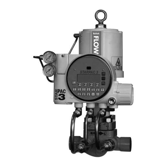
Flapper Algorithm The StarPac 3 Positioner is an electric feedback instrument. Figure 1 shows a StarPac 3 installed on a double-acting actuator for air-to-open action. Positioning is based on a balance of two signals: one proportional to the modulator input signal and the other proportional to the stem position. -
Page 14: Mounting And Installation
Stem Clamp Follower Pin Take-off Arm Bolts Metal Washers To mount the StarPac 3 positioner to a Flowserve Valtek linear Mark One valve, refer to Figure 2 and proceed as out- lined below. The following tools are required: • 9/16” open-end wrench (or 1/2” for spud sizes 2.88 and smaller) • 7/16” box wrench • 3/8” open-end wrench... - Page 15 8.2 Mounting to Standard Flowserve Valtek Rotary Valves The standard rotary mounting applies to Flowserve Valtek valve/actuator assemblies that do not have mounted volume tanks or handwheels. The standard mounting uses a linkage directly coupled to the valve shaft. This linkage has been designed to allow for minimal misalignment between the positioner and the actuator.
- Page 16 The pin should extend appro- ximately 1/16” past the take-off arm. When properly adjusted, securely tighten the bracketing bolts. 7. Tube the StarPac 3 positioner to the actuator according to the instructions given in Section 8.4, “Tubing Posi- tioner to Actuator.”...
-
Page 17: Optional Flowserve Valtek Rotary Mounting Procedure
10. Connect regulated air supply to appropriate port in manifold. 11. Remove main cover and perform a stroke calibration using the key pad (refer to the StarPac 3 User Interface Manual. Make sure the StarPac 3 has been configured with the proper air action. -
Page 18: Tubing Positioner To Actuator
The StarPac 3 positioner is insensitive to supply pressure changes and can handle supply pressures from 30 to 150 psig. A supply regulator is recommended if the customer will be using the diagnostic features of the StarPac 3 but is not required. -
Page 19: Wiring And Grounding Guidelines
Conduit fittings must match equipment housing threads before installation. If threads do not match, obtain suitable adapters or contact a Flowserve representative. In all cases always use suitable rated cable glands. Unused openings shall be installed with suitably rated close-out plugs. -
Page 20: Shielding Versus Grounding
9.1 Shielding Versus Grounding All signals to the StarPac 3 unit should be in shielded cables. Shields must be tied to a ground at only one end of the cable to provide a place for environmental electrical noise to be removed from the cable. A ground wire (unlike a shield) is attached at both ends to provide a continuous path for electrical conductivity. -
Page 21: Wiring The Starpac 3 System
C. Therefore, select appropriate rated cable. STOP! 10.2 Wiring Connections o connect the wiring to the StarPac 3 unit, refer to Figures 6 and Table IX, and then proceed as follows. Figure 6: User Interface Terminal Pinouts 10 11 13 14 15... - Page 22 (The system must have 24 VDC power for operation). NOTE: The StarPac 3 unit remembers the operating mode setting (automatic or manual) from the last time the unit had power. When power to the system is turned on again, the unit will resume operation in the previ- ous mode.
-
Page 23: Setting The Jumpers
StarPac Intelligent Control System FCD VLENIM0066-02 02/10 ® 10.3 Setting the Jumpers The StarPac 3 system has several jumpers that are used to configure the analog and discrete I/O. The keypad must be removed to view or change the jumper settings. 1. Contact Relay Setting On the lower right hand side of the electronic board assembly is a three position jumper labeled “JP4.”... -
Page 24: Rs-485 Communication Configurations
11.2 to 11.5. The communication settings for each port will need to be set on the StarPac 3 device through the keypad. Refer to the StarPac 3 User Interface Manual for instructions on how to change the communication settings on the StarPac 3. -
Page 25: Selecting Correct Modbus Transmission Mode
• USB • Infrared 1. When RS-485 is selected, the StarPac 3 device will need to be wired correctly. Refer to Figure 6 and Table IX for wiring connection instructions. Follow the instructions as outlined in sections 11.2 to 11.5 to configure Com Port B. -
Page 26: Starpac 3 Calibration
StarPac Intelligent Control System FCD VLENIM0066-02 02/10 ® 12 StarPac 3 Calibration For complete calibration instructions, refer to the StarPac 3 Interface Manual or the on board help in the StarTalk XP interface software. 13 StarPac 3 Configuration For complete configuration instructions, refer to the StarPac 3 User Interface Manual or the on board help in the Star- Talk XP interface software. -
Page 27: Position Feedback System
14.3 Position Feedback System The position feedback linkage of the StarPac 3 system is a critical part of the system. This linkage is also used in the StarPac 3 to calculate the valve’s CV for a given stroke for flow measurement. This linkage should be lubricated and checked periodically for tight, smooth operation. - Page 28 StarPac Intelligent Control System FCD VLENIM0066-02 02/10 ® release the locking sleeve of the Lemo™ connector by moving the collar away from the sensor and disconnect the connector from the sensor. Swing the sen- sor conduit out of the way (refer to Figure 10). Figure 10: Disconnecting Lemo Connector 4.
-
Page 29: Pressure Sensor Cable Replacement
Figure 11: Pressure Sensor and Thermocouple Terminal Strip 7. Remove the pressure sensor cable from the conduit. 8. Feed the new pressure sensor cable into the conduit. Then feed the bare end of the cable into the StarPac 3 housing through the conduit entry. -
Page 30: Thermocouple Replacement
StarPac Intelligent Control System FCD VLENIM0066-02 02/10 ® 14.6 Thermocouple Replacement In normal configuration, the thermocouple does not penetrate the valve body wall. Depres- surizing the body is not necessary when replacing the thermocouple. WARNING: If the StarPac II was ordered with a special thermocouple option, STOP! verify the need to depressurize the body before proceeding. -
Page 31: Keypad Assembly Replacement
12. Check that all the fittings are tight. 14.7 Keypad Assembly Replacement If, after consulting with the local Flowserve or factory representative, the StarPac 3’s keypad is found to be defective and needs replacement, refer to Figure 24 and proceed as follows. - Page 32 StarPac Intelligent Control System FCD VLENIM0066-02 02/10 ® Figure 13: Driver Module Assembly Driver O-ring Module Assembly Install barbed fitting after driver module is installed in housing Pressure Modulator Connector Position wires 1. Make sure the valve is bypassed or in a safe condition. straight along side of Driver Hall Sensor...
- Page 33 14. Grasp the base of the driver module and turn it counter clockwise to remove. After it is threaded out, carefully retract the driver module from the housing. 15. Remove the barbed fitting orifice (See Figure 16) from the side of the new driver module using the 1/4” nut- driver. flowserve.com...
- Page 34 StarPac Intelligent Control System FCD VLENIM0066-02 02/10 ® Figure 16: Driver Module Barbed Fitting Orifice Driver Module Cover 16. Verify the O-ring is in place on the top of the new driver module. Lay the wires back along the side of the driver module as shown in Figure 13 and hold the wires in position by hand.
-
Page 35: Regulator Replacement
30. Re-install the keypad. Insert the two retaining screws and tighten evenly, using a Phillips a screwdriver. Do not over-tighten. 31. Reconnect power and air supply to the positioner and perform a stroke calibration. Refer to the Calibration section of the StarPac 3 User Interface Manual. 32. Reinstall all covers. 14.9 Regulator Replacement The Regulator reduces the pressure of the incoming supply air to a level that the driver module can use. - Page 36 StarPac Intelligent Control System FCD VLENIM0066-02 02/10 ® • Calibrated pressure gauge (0 to 30 psi) • 1/16” flexible tubing • Barbed Tee (Clippard Minimatic part number T22-2 or equivalent) • 3/32” Allen wrench • 3/8” open-end wrench WARNING: Observe precautions for handling electrostatically sensitive devices. STOP! 1. Make sure the valve is bypassed or in a safe condition. 2. Remove the main cover. 3.
-
Page 37: Checking Or Setting The Driver Module Minimum Pressure
(Clippard part No. 15010 or equivalent). 9. Remove the No. 10-32 x 1/16 orifice (Figure 16) from the driver module using a 1/4-inch nut driver. 10. Screw in the 10-32 extension followed by the 10-32 x swivel run tee. flowserve.com... - Page 38 StarPac Intelligent Control System FCD VLENIM0066-02 02/10 ® Figure 18: Driver Module Minimum Pressure Check No. 10-32 Extension (Clippard Part No. 15010) Minimum Pressure Test Port No.10-32 x Barb No.10-32 x .016 No.10-32 x Swivel Orifice Tee (Pneumadyne Pressure from Internal Part No.
-
Page 39: Spool Valve Cover Replacement
Replacing the Spool Valve To replace the spool valve, refer to Figures 14, 15 and 24 and proceed as outlined below. The following tools are re- quired: • Phillips screwdriver flowserve.com... -
Page 40: Stem Position Sensor Replacement
StarPac Intelligent Control System FCD VLENIM0066-02 02/10 ® 1. Make sure the valve is bypassed or in a safe condition. 2. Disconnect the power and air supply to the unit. 3. Remove the spool valve cover by removing the screw and sliding the cover assembly backwards until the tab is clear of the slot. -
Page 41: Main Pcb Assembly Replacement
To replace the main PCB assembly, refer to Figure 20 and proceed as outlined below. The main PCB assembly consists of three boards. The top board will have to be separated from the assembly. The bottom two boards will not have to be separated and will remain together. flowserve.com... - Page 42 StarPac Intelligent Control System FCD VLENIM0066-02 02/10 ® The following tools are required: • Phillips screwdriver WARNING: Observe precautions for handling electrostatically sensitive devices. STOP! 1. Make sure the valve is bypassed or in a safe condition. 2. Disconnect the power and air supply to the unit. 3.
-
Page 43: Customer Interface Board Replacement
The customer interface board provides a connection point inside the explosion-proof housing for all hookups to the positioner. To replace the customer interface board, refer to Figures 5 and 24 and proceed as outlined below. The following tools are required: • Phillips screwdriver flowserve.com... -
Page 44: Optional Vented Design
Two chambers must be vented on the StarPac 3: the driver module and the spool valve chamber (Figures 22 and 23). The driver module vent is located on the driver module cover. Install a tube fitting into the driver module cover (Figure 22). - Page 45 Pressures greater than 8 psig will cause vented gas to leak past the spool cover O-ring to the atmosphere and will result in overshoot of the positioner. Figure 23: Spool Cover Vent 3/8” NPT x 3/8” Swagelok Tube Fitting Maximum Allowable Spool Back Pressure 8 psig (0.55 barg) Customer Connection 3/8” Tubing flowserve.com...
-
Page 46: Parts List
® 16 Parts List Table XI: Positioner Parts List Item No. Part Item No. Part Housing StarPac 3 Positioner Driver Module Assembly Main Housing Cover Hex Barbed Fitting with Captive O-ring O-ring, Main Housing Cover Flexible Tubing Screw, Anti-rotation Screw, Driver to Housing... - Page 47 StarPac Intelligent Control System FCD VLENIM0066-02 02/10 ® Figure 24: Positioner Exploded View flowserve.com...
-
Page 48: Starpac 3 Spare Parts Kits
StarPac Intelligent Control System FCD VLENIM0066-02 02/10 ® 17 StarPac 3 Spare Parts Kits Table XII: StarPac 3 Spare Parts Kits Item No. Description Quantity Item No. Description Quantity Kit 1: Driver Module Assembly (Non-vented), P/N 226733.999.000 Kit 7: Soft Goods Kit, P/N 199789.999.000... -
Page 49: Starpac 3 Mounting Kits
StarPac Intelligent Control System FCD VLENIM0066-02 02/10 ® StarPac 3 Mounting Kits Table XIII: Flowserve Valtek Linear Mounting Kits 25 in 50 in 100-200 in Spud Standard Handwheel Standard Handwheel Standard Handwheel 2.00 234430 234431 234432 234433 2.62 164435 164436... -
Page 50: Pressure Sensor Spare Parts Kits
StarPac Intelligent Control System FCD VLENIM0066-02 02/10 ® 20 Pressure Sensor Spare Parts Kits Table XVI: Pressure Sensor Gasket Kits (See Body Mount Sensor Configurations Drawing and Remote Sensor Configurati- on for item numbers. Note: Kits 1 thru 4 will service two body or two remote-mount pressure sensors from any one of the pressure sensor configuration drawing numbers listed below each table. - Page 51 Purge and Isolation Valves, Part No. 134558.999.000 Swagelok nut Swagelok ferrules Temperature extended fitting Purge valve Isolation valve Adapter fitting NOTE: Kit will service two remote-mount pressure sensors. See Table XIIX for tubing. (Wet-leg tubing wall thickness must be 0.065-inch). flowserve.com...
- Page 52 StarPac Intelligent Control System FCD VLENIM0066-02 02/10 ® Figure 25: Body-mount Sensor Configurations Boss on valve body Electrical connection cable Tubing, 0.035 wall thickness Tube nut Tube ferrule set Sensor nut Environmental O-ring Sensor fitting 11. Length adapter fitting Environmental O-ring 12.
-
Page 53: Temperature Sensor Spare Parts Kits
Table XXVIII: Temperature Probe Kits (See temperature sensor configuration drawing for item numbers.) Item No. Description Quantity Kit 12 - Standard Temperature Probe Replacement, Configuration, Part No. 083855.999.000 Standard temperature probe Item No. Description Quantity Kit 13 - Through Hole Temperature Probe Replacement, Part No. 105646.999.000 Through hole temperature probe flowserve.com... -
Page 54: Starpac 3 Stainless Steel Tubing Kits
StarPac Intelligent Control System FCD VLENIM0066-02 02/10 ® 22 StarPac 3 Stainless Steel Tubing Kits Figure 27: StarPac 3 Temperature Sensor, Flush-mount Version 1. Temperature probe. 2. Tubing, 0.035 wall 3. Tube fitting Temperature probe boss Table XXIX: 316 Stainless Steel Tubing... -
Page 55: Starpac 3 System Troubleshooting
StarPac Intelligent Control System FCD VLENIM0066-02 02/10 ® 23 StarPac 3 System Troubleshooting Table XXX: StarPac 3 System Troubleshooting Chart Failure Probable Cause Corrective Action Local display not on 24 VDC not on or set correctly Verify power supply is outputting 24 VDC (termi-... -
Page 56: Starpac 3 Pressure Sensor Troubleshooting
StarPac Intelligent Control System FCD VLENIM0066-02 02/10 ® 24 StarPac 3 Pressure Sensor Troubleshooting Figure 28: StarPac 3 Pressure Sensor Troubleshooting Chart Pressure reading is incorrect Is pressure slightly off or saturated? Slightly Saturated Is reading Recalibrate saturated sensor low or high? -
Page 57: Starpac 3 Electronics Initialization Procedure
25 StarPac 3 Electronics Initialization Procedure The StarPac 3 has an initialize interlock feature. Every time power is cycled the unit will not return to normal operation, but will be interlocked out in TEST mode until the unit is manually put back into operation. -
Page 58: How To Order
StarPac Intelligent Control System FCD VLENIM0066-02 02/10 ® 26 How to Order Table XXXII: How to order Positioner Replacement Code Example Selection Model StarPac 3 Communication Modbus Aluminum, white paint (Valtek) Housing Material Stainless, No paint (Valtek) General Purpose Certifications... - Page 60 Flowserve products. The purchaser/user should read and understand the Installation Operation Maintenance (IOM) instructions included with the product, and train its employees and contractors in the safe use of Flowserve products in connection with the specific application.
Need help?
Do you have a question about the StarPac 3 and is the answer not in the manual?
Questions and answers