Table of Contents
Advertisement
Quick Links
Configuration Guide : V150
The V150 shares option cards with the V200. All option cards that operate in the
V150 can operate in the V200, and all except the V200 PSU Card will work in the
V150. This guide outlines some sample configurations, the essential minimal
configurations, and the parts required.
Basic "Legal" Configuration
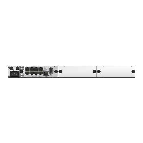
Unlike the V100, which had in-built serial data and IP ports, the V150 chassis offers
no actual ports apart from the power socket(s) and the connection socket for the
M&C cable.
The V150 ships in one of two power configurations:
VI68150
Chassis
or with the factory fitted redundant second power supply fitted:
VI68150
Chassis
VI68160
V150 Redundant PSU
If ordered without redundant power, the hole (above/right of the main IEC inlet) is
filled. If ordered with redundant power, the hole is replaced with a cable "pigtail"
connector with an IEC socket extending from the rear of the unit, for the second
power supply. There is no point sharing one IEC inlet for two power supplies if you
are going to have potential power issues outside the Vocality unit.
A basic "legal" configuration does not need the redundant second power supply. It
does, however, need a Standard CPU Card.
This minimum configuration offers a single IP port, and a single serial data port.
Whilst physically minimal, it could still be used as a powerful VoIP gateway device
with SIP license. The items used in this configuration (exclusive SIP licenses) are:
VI68150
Chassis
VI68151
Standard CPU Card
Page 1 of 5
Advertisement
Table of Contents

Summary of Contents for Vocality V150
- Page 1 The V150 shares option cards with the V200. All option cards that operate in the V150 can operate in the V200, and all except the V200 PSU Card will work in the V150. This guide outlines some sample configurations, the essential minimal configurations, and the parts required.
- Page 2 Basic Voice Configuration The V150 above is equipped with a Standard CPU Card. The Vocality range includes a number of modules which can convert a Standard CPU Card into another card – an Analogue Voice Card, or an Ethernet Switch Card, for example.
- Page 3 Relay. This allows up to 60 (or 48 using 2 x T1) channels to concurrently deliver STU III, analogue STE and digital STE connectivity through a single V150 chassis. Such a configuration could be used if IP is being used as a link aggregate, and secure voice needs to be delivered over the link (eg.
- Page 4 4 channels, with 2 wire comms on the second bank of 4. The V150 will take up to 3 voice configurations of this type – delivering a maximum of 24 voice circuits of which 12 can be configured to be 4 wire.
- Page 5 Modules are free standing feature devices that enhance a V50plus, or a Standard CPU Card with a functionality. An Analogue FXS Voice Card as used in the V150 comprised a Standard CPU Card and an Analogue FXS Voice Module. This Module can be taken from an Analogue FXS Voice Card and installed into a V50plus.
Need help?
Do you have a question about the V150 and is the answer not in the manual?
Questions and answers