Advertisement
Advertisement
Table of Contents

Related Manuals for Mark-10 Series 5

Summary of Contents for Mark-10 Series 5
- Page 1 Series DIGITAL FORCE GAUGES User’s Guide...
-
Page 2: Table Of Contents
Thank you for purchasing a Mark-10 Series 5 digital force gauge, designed for tension and compression testing applications from 0.12 to 2,000 lbF (0.5 N to 10,000 N) full scale. The Series 5 is an essential component of a force testing system, typically also comprising a test stand, grips, and data collection software. -
Page 3: Overview
Series 5 Digital Force Gauges User’s Guide 1 OVERVIEW 1.1 Included Items Part No. M5-012 – M5-50 – M5-200 – M5-1000 – Qty. M5-20 M5-100 M5-500 M5-2000 M5-2-COF Description 12-1049 12-1049 12-1049 12-1049 12-1049 Carrying Case 08-1022 08-1022 08-1022 08-1022... -
Page 4: Power
Series 5 Digital Force Gauges User’s Guide accumulate in the sample during testing. Extra bodily protection should be worn if a destructive failure of a test sample is possible. 6. In certain applications, such as the testing of brittle samples that can shatter, or other applications that could lead to a hazardous situation, it is strongly recommended that a machine guarding system be employed to protect the operator and others in the vicinity from shards or debris. -
Page 5: Setup
The round steel insert with a hole in the back of the housing is provided to withstand the load during a test. A mating dowel pin should be used (see illustration below). Mounting plates on Mark-10 test stands include a dowel pin and clearance holes for the four threaded holes located near the corners of the housing. -
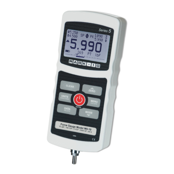
Page 6: Home Screen And Controls
If using a grip or fixture from a supplier other than Mark-10, ensure that it is constructed of suitably rugged materials and components. - Page 7 Series 5 Digital Force Gauges User’s Guide and on. Primary reading / The current displayed force reading. See Operating Modes section for Kinetic COF details. For the M5-2-COF gauge, this reading represents the kinetic coefficient of friction when the gauge is set to COF unit of measurement (see Units indicator below) and has completed an Average sequence (see Operating Modes section for details).
-
Page 8: Operating Modes
“OVER” to indicate an overload. A continuous audible tone will be sounded until the MENU key has been pressed or the load has been reduced to a safe level. Five operating modes are possible with Series 5 gauges. To cycle between the modes, press MODE while in the home screen. - Page 9 Series 5 Digital Force Gauges User’s Guide 5.1 Real time (RT) The primary reading corresponds to the live measured reading. 5.2 Peak Compression (PC) The primary reading corresponds to the peak compression reading observed. If the actual force decreases from the peak value, the peak will still be retained in the primary reading area of the display.
- Page 10 Series 5 Digital Force Gauges User’s Guide AVERAGE MODE SETTINGS Trigger Force 1.00 lbF Initial Delay 1.0 sec. Averaging Time 5.0 sec. Parameter Description The minimum force required to start the averaging sequence. Toggle between Trigger Force compression and tension directions by pressing the DIRECTION key. Initial delay follows the trigger force.
- Page 11 Series 5 Digital Force Gauges User’s Guide 5.6 External Trigger (ET) This mode of operation is useful for measuring electrical contact activation force as well as synchronization of multiple instruments for a “snapshot” view of applied forces. It is possible to capture the reading with a normally open contact (high to low transition of the trigger signal) or a normally closed contact (low to high transition).
-
Page 12: Digital Filters
Series 5 Digital Force Gauges User’s Guide Note: Custom cabling is required to connect to a switch, or to connect a switch and a Mark-10 test stand simultaneously. 6 DIGITAL FILTERS Digital filters are provided to help smooth out the readings in situations where there is mechanical interference in the work area or test sample. - Page 13 7.4 Using Set Points to Control a Mark-10 Test Stand When using set points to stop/cycle Mark-10 motorized test stands, the upper and lower set points must be set to opposite measuring directions. Both set points must be set, even if the intended application is to stop/cycle at only one of the set points.
-
Page 14: Data Memory And Statistics
8 DATA MEMORY AND STATISTICS Series 5 gauges have storage capacity of 1,000 data points. Readings may be stored, viewed, and output to an external device. Individual, or all, data points may be deleted. Statistics are calculated for the data presently in memory. -
Page 15: Communications And Outputs
If no option is selected, this screen will be displayed indefinitely, or until battery power has been depleted. 9 COMMUNICATIONS AND OUTPUTS Communication with Series 5 force gauges is achieved through the micro USB or 15-pin serial ports located at the bottom of the instrument, as shown in the illustration in the Power section. Communication is possible only when the gauge is in the main operating screen (i.e. - Page 16 Select the baud rate as required for the application. It must be set to the same value as the receiving device. When communicating with a Mark-10 test stand controller, the baud rate must be set to 115,200. 9.1.2 Data Format Select the desired data format.
- Page 17 Series 5 Digital Force Gauges User’s Guide 9.2 Mitutoyo BCD settings This output is useful for connection to data collectors, printers, multiplexers, or any other device capable of accepting Mitutoyo BCD data. Individual data points may be transmitted by pressing DATA or by requesting it from the Mitutoyo communication device (if available).
- Page 18 9.6 Command Set / Gauge Control Language 2 (GCL2) Series 5 force gauges may be controlled by an external device through the RS-232 or USB channels. The following is a list of supported commands and their explanations. All commands must be terminated by a CR (Carriage Return) character, 0x0D, or a CR-LF (Carriage Return –...
- Page 19 Series 5 Digital Force Gauges User’s Guide Request Readings Request the displayed reading (dependent on operating mode) Request the current (real time) reading Request the peak tension reading Request the peak compression reading Request the reading obtained during the External trigger mode...
-
Page 20: Calibration
Series 5 Digital Force Gauges User’s Guide Averaging Enable Average mode Disable Average mode Select Average mode (if enabled) for primary reading Average time. n=0.1-300.0 seconds DELn Initial delay. n=0.1-300.0 seconds TRFn Trigger force. n=value (+ for compression, - for tension) - Page 21 Series 5 Digital Force Gauges User’s Guide 10.2 Calibration Procedure 1. Select Calibration from the menu. The display appears as follows: CALIBRATION To invert the display, press the DIRECTION button, then press ENTER. 2. Press DIRECTION to invert the display, if desired. ENTER to continue. The display appears as...
- Page 22 Series 5 Digital Force Gauges User’s Guide CALIBRATION OFFSET Please wait… CALIBRATION CALIBRATION OFFSET OFFSET Sensor passed Sensor failed Analog passed Analog failed If failed: 6. The following screen appears after the offsets have been calculated: CALIBRATION COMPRESSION Attach necessary weight fixtures, then press ENTER.
- Page 23 Series 5 Digital Force Gauges User’s Guide CALIBRATION COMPRESSION Ensure no load, then press ZERO. Remove the load applied in Step 8, leave the fixtures in place, then press ZERO. 10. The display appears as follows: CALIBRATION COMPRESSION Apply load...
- Page 24 Series 5 Digital Force Gauges User’s Guide CALIBRATION COMPLETE Save & exit Exit w/o saving To save the calibration information, select “Save & exit”. To exit without saving the data select “Exit without saving”. 14. Any errors are reported by the following screens: CALIBRATION Units must be gF.
-
Page 25: Passwords
Series 5 Digital Force Gauges User’s Guide 11 PASSWORDS Two separate passwords may be set to control access to the Calibration section and to the menu and other keys. To access the passwords setup screen, select Passwords from the menu. The display... -
Page 26: Other Settings
If the password has been misplaced, it can be reset. Press ENTER to generate a request code. The request code must be supplied to Mark-10 or a distributor, who will then provide a corresponding authorization code. Enter the activation code to disable the password. - Page 27 Series 5 Digital Force Gauges User’s Guide 12.2 Backlight Although the backlight may be turned on and off at any time by pressing the BACKLIGHT key, there are several available initial settings (applicable upon powering on the gauge). To access these settings, select Backlight from the menu.
- Page 28 Series 5 Digital Force Gauges User’s Guide 12.5 Initial settings This section is used to configure the initial settings upon powering on the gauge. The initial units of measurement and the primary reading measurement mode may be configured. To access these settings, select Initial Settings from the menu.
-
Page 29: Specifications
Series 5 Digital Force Gauges User’s Guide 13 SPECIFICATIONS 13.1 General Accuracy: ±0.1% of full scale Sampling rate: 7,000 Hz Power: AC or rechargeable battery. Low battery indicator appears when battery level is low, and gauge powers off automatically when power reaches critical stage. - Page 30 Series 5 Digital Force Gauges User’s Guide 13.2 Factory Settings Parameter Setting Set points Upper Disabled (defaults to 80% of full scale, compression, when enabled) M5-2-COF: Disabled (defaults to 0.8 COF [tension] when enabled) Lower Disabled (defaults to 40% of full scale, compression, when enabled) M5-2-COF: Disabled (defaults to 0.4 COF [tension] when enabled)
- Page 31 Series 5 Digital Force Gauges User’s Guide 13.3 Capacity x Resolution Model M5-012 0.12 x 0.00002 2 x 0.0005 50 x 0.01 0.5 x 0.0001 500 x 0.1 M5-025 0.25 x 0.00005 4 x 0.001 100 x 0.02 1 x 0.0002 1000 x 0.2...
- Page 32 Series 5 Digital Force Gauges User’s Guide 13.4 Dimensions (in [mm]) M5-012 – M5-500 Thread Flat M5-012 – M5-100, M5-2-COF #10-32M UNF 5/16 [7.94] M5-200 – M5-500 5/16-18M UNC 5/16 [7.94] M5-1000 – M5-2000...
- Page 33 Series 5 Digital Force Gauges User’s Guide NOTES:...
- Page 34 Series 5 Digital Force Gauges User’s Guide Mark-10 Corporation has been an innovator in the force and torque measurement fields since 1979. We strive to achieve 100% customer satisfaction through excellence in product design, manufacturing and customer support. In addition to our standard line of products we can provide modifications and custom designs for OEM applications.
Need help?
Do you have a question about the Series 5 and is the answer not in the manual?
Questions and answers