Table of Contents
Advertisement
Advertisement
Table of Contents

Related Manuals for Nitchi MH-5

Summary of Contents for Nitchi MH-5
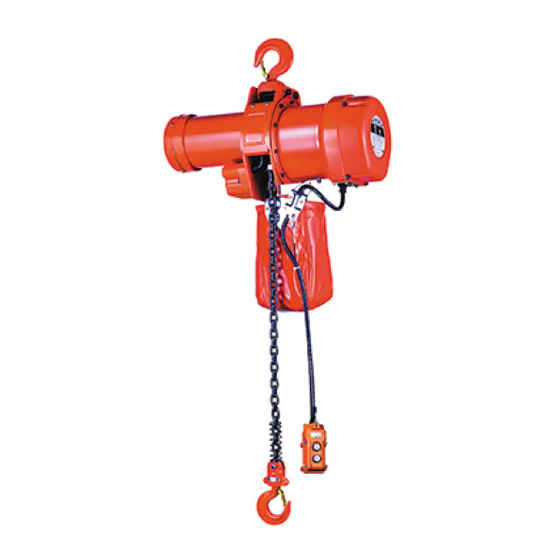
- Page 1 ELECTRIC CHAIN HOISTS MH-5 / MHT-5 / MHC-5 SERVICE MANUAL No.1...
-
Page 2: Table Of Contents
Contents 1.Precautions 1 2.Inspection & Replacement/Adjustment 1 2−1.Load chains 1 2−2.Hooks 1 2−3.Electromagnetic brake 2 2−4.Lubricant oil 4 3.Disassembly 5 3−1.Disassembly procedures 5 3−2.Electromagnetic brake - Inspections during disassembly 8 4.Assembly 9 4−1.Frame section 9 4−2.Gear section 11 4−3.Motor section (incl. Electromagnetic brake) 15... -
Page 3: 1.Precautions
Replace if it is damaged. ・ Never reuse deformed, worn or corroded parts. Always replace them with new ones. ・ Never use other than NITCHI genuine parts. 2 . Inspections & Replacement/Adjustment 2 − 1 . Load chains Measure dimensions φ d (link diameter) and P (link pitch) as shown in Table 1. -
Page 4: 2−3.Electromagnetic Brake
52.3 52.3 2 − 3 .Electromagnetic brake Electromagnetic brake for 3-Phase models (MH-5 & MHT-5) ・ Measure the dimension of the brake clearance between (p/C59-4) Armature and (p/C59-5) Brake coil (Dimension A as per Fig 2 below) with a thickness gauge. - Page 5 Electromagnetic brake for 1-Phase model (MHC-5) ・ Measure the dimension of the brake clearance between (p/C59-4) Armature and (p/C59-5) Brake coil (Dimension A as per Fig 3. below) with a thickness gauge. The brake needs adjustment according to the procedures through 1-8 as given below if the measured value is 0.8mm or over at the condition the brake is being mounted on the hoist (or, 1.8mm or over if the brake is set loose.) ③...
-
Page 6: 2−4.Lubricant Oil
Table 3 provides recommended oil type and quantity per model/capacity to replace or replenish the oil. Table 3 Oil type & quantity 3 . Lubrication on Load chain MH-5・MHT-5 MH-5 MHT-5 Make sure the load chain is MHC-5 0.5∼ 1t 2∼... -
Page 7: 3.Disassembly
3 . Disassembly 3 − 1 . Disassembly procedures ② ② ③ ① 1. Unjoint (p/B32) Chain bucket pin 2. Take off (p/C12) Switch cover and disconnect the wirings of ① (p/C563) and the hanging chain and remove Power source cable, ② (p/C564) Pendant control cable and ③ (p/C635) (p/B27) Chain bucket. - Page 8 12.Dismantle (p/C59) Brake unit. 13.Loosen (p/C664) Through bolts 14.Take off (p/C49) Pipe for lead and remove (p/C45) Shield. wire and (p/C3) Stator for motor. 15.Pull out (p/A2) Pinion shaft 16.Remove (p/A1) Gear box. 17.Disengage whole the mechanical (w/ Rotor). brake set and the third pinion set.
- Page 9 24. Unfasten (p/B538) Nut and 25. Release (p/B566) Retaining ring 26. Take off (p/B28) Hanging plate (p/C525) Cap bolt, to separate and remove (p/B36) Limit lever. for (p/B27) chain bucket, (p/C44) Motor flange and (p/B35) (p/B537) Springs for B6 then Stay pipe B <0.5&1t>...
- Page 10 ⑦ Brake stay bolt ⑨ ⑧ ① ⑧ Fixing screw for Detent plate ⑨ Brake auxiliary spring C59-8 ⑩ Brake spring C59-7 ⑦ ⑩ ⑥ Fig. 6-a MH-5 & MHT-5 ④ ③ ② ⑤ ① ⑨ ⑧ ⑦ ⑩ ⑥ Fig. 6-b MHC-5...
-
Page 11: 4.Assembly
4 . Assembly 4 − 1 . Frame section Please replace the parts with new ones if they fall into the following conditions. 1 . Gear-/Motor-side plates : Bearings (p/B507,508) rattle on the holes, or wear or (p/B1,B29) deformation on the hole for (p/B18) Top hook pin is found. - Page 12 B567 Support spring for 2∼5t capacity 4. Grease to the stay bolt beneath 5. Put 2 pcs. (p/B537) Springs for 6. Put also (p/B567) Supporting (p/B6) Load chain guide and B6 in the position as above. spring with (p/B568) Cap bolt in furnish (p/B10) Handle over it.
-
Page 13: 4−2.Gear Section
(p/A513) Retaining ring. tooth with (p/A16) Pawl properly. 7. Furnish the third pinion and the 8. For MH-5/MHT-5 0.5-1t and MHC-5, 9. Put (p/A501) O-Ring on (p/A1) mechanical brake assemblies with clamp (p/A553) Ball bearing on Gear box with bond. - Page 14 10. Align (p/A1) Gear box with (p/B1) Gear-side plate using (p/A558) Spring pins, then fix with (p/A519, A562) Cap bolts. ※2 A562 is to fix (p/B30-1,B30-2) Body covers B and is different from A519 in size. ※1 (p/A7) Load gear aspect: 0.5∼...
- Page 15 ※Mechanical brake assembly ② ① ③ ⑥ ④ ⑤ ⑦ 1 .Follow procedures through ① to ⑦ as the above photos. ・ At procedure ⑦, screw up (p/A3) Pinion gear to the bottom first, then insert (p/A15) Check washer. Be careful of its arm's position. The arm of Check washer hits the projection of the pinion gear when it gets loose, and it stops the rotation.
- Page 16 2 .Adjust the clearance between Check washer arm and the projection of Pinion gear to 1mm or less by meshing (p/A15) Check washer on the different threads of (p/A4) Second pinion gear and/or by turning over Check washer to the other face. - 14 -...
-
Page 17: 4−3.Motor Section (Incl. Electromagnetic Brake)
4 − 3 . Motor section (incl. Electromagnetic brake) Replace the parts with new ones if they fall into the following conditions. 1 . Any wear is found on the helical gear or the spline portion of (p/A2) Pinion shaft (w/ Rotor). 2... - Page 18 7. Fix (p/C1) Motor cover with (p/C524) Screws. ※Electromagnetic brake unit assembly Please follow as illustrated below. Be sure to align both the center of (p/C4) Brake wheel and (p/C59-1) Brake base plate in assembly. Refer to Section 2-3. for the brake clearance inspection & adjustment. - 16 -...
-
Page 19: 4−4.Limit Switch Section
4 − 4 . Limit switch section Assembly procedures Parallel 1. Set (p/C634) Limit switch at the 2. Fit (p/C32) Limit switch plate 3. Connect (p/C32) Limit switch plate neutral position by turning the with (p/C634) Limit switch so to (p/B29) Motor-side plate with key shaft so that its arrowed that the labeled side of the (p/C630) Cap bolts, and pass... -
Page 20: 4−5.Electrical Parts & Wiring
4 − 5 . Electrical parts & Wiring Assembly procedures 1. Outfit (p/A2) Pinion shaft with 2. Outfit (p/A2) Pinion shaft with 3. Lay (p/A560) Gasket for A29 on (p/A32) Bearing bush in case of (p/A509) Ball bearing. (p/A1) Gear box and coat with MHT 0.5∼... - Page 21 7. Put in (p/C694) Cord locks and 8. Close (p/B30-1) Body cover B with 9. Close (p/B30-2) Body cover B while set (p/C563) Power source cable (p/B542) Screws. retaining (p/C563) Power source and (p/C564) Pendant control cable by (p/C34) Supporter for cable into (p/A29) Switch holder.
-
Page 22: 4−6.Top Hook Assembly
4 − 6 .Top hook assembly ・ 0.5∼ 3t Capacities B29 Motor-side plate ・ 5t Capacity ・ Be sure to grease to (p/B18) Top hook pin for assembly. ・ Split (p/B514) Split pins at 60 degree. - 20 -... -
Page 23: 4−7.Load Chain, Bottom Hook Assembly, Stop Holder
4 − 7 . Load chain, Bottom hook assembly, Stop holder & Chain bucket assembly ・ Load chain Pilot chain 'C' link B26 Load chain 1. Joint (p/B26) Load chain to the 2. Press 'DOWN' push button to feed loose-end side of the pilot chain (p/B26) Load chain into the unit using a 'C' link (open link). -
Page 24: 4−8.Lubricant Oil Pouring
※Bottom hook assembly 1 . Attach (p/83) Tail wheel collars to (p/D6) Tail wheel then assemble to the bottom hook with (p/D8-11) Tail wheel guides B. 2 . Grease to (p/D9) Tail wheel pin and insert to the position. 3 . Fit (p/D8-10) Tail wheel guide A and fasten up with bolts. (Slot it into the groove on (p/D9) Tail wheel pin as the photo given below.) (p/D6) Tail wheel (p/D8-11) Tail wheel guide B... - Page 25 5. MH-5 Spare Parts List Recommended Parts marked ★ is for Light Duty use and ☆ is for Heavy Duty use. Nos. Part Code Part Part Name Remarks Number used 0.5t GEAR BOX GMH5A001U LMH5A001U LMH5A002U PINION SHAFT GMH5A002U JMH5A002U ☆...
- Page 26 Nos. Parts Code Part Part Name Remarks Number used 0.5t MOTOR COVER GMH5C001 LMH5C001 200V 200V 200V LMH5C003S STATOR FOR MOTOR GMH5C003S JMH5C003S Dual Dual ☆ Dual LMH5C003ST GMH5C003ST JMH5C003ST 400V 400V 400V LMH5C003SB GMH5C003SB JMH5C003SB ★☆ BRAKE WHEEL GMH5C004U LMH5C004U SWITCH COVER GMH5C012...
- Page 27 Parts Code Nos. Part Remarks Number used 0.5t TOP HOOK ASSEMBLY MH4005D01T MH4010D01T LMH5D001U MMH5D001U MH4050D01T CHAIN STOP PLATE HH4100040 ☆ YOKE PIN (W/NUT) MH4030D03 ☆ TAIL WHEEL PMH5D006T ★☆ BOTTOM HOOK ASSEMBLY GMH5D008U MH4010D08X LMH5D008U MH4028D08X PMH5D008U ☆ TAIL WHEEL PIN MH4030D09 ★☆...
- Page 32 NITCHI CO., LTD. No.7-17, 4-CHOME, YOSHITA, HIGASHI-OSAKA, OSAKA, JAPAN 578-0924 http://www.nitchi.co.jp/ MH-5-001 (2007.11.30)
Need help?
Do you have a question about the MH-5 and is the answer not in the manual?
Questions and answers