
Related Manuals for iCanTek myDVR1630

Summary of Contents for iCanTek myDVR1630
- Page 1 Operational Guide Preliminary The contents of this document can be changed without prior notice.
-
Page 2: Table Of Contents
Operational Guide TABLE OF CONTENTS 1. Introduction....................... 5 1.1. Overview......................5 1.2. Summary of the Specification of MyDVR1630/930........... 5 1.3. Packing List ...................... 7 2. Product Description ....................9 2-1. Front Panel....................... 9 2-2. Rear Panel ..................... 11 2-3. Remote Controller ..................12 2-3-1. - Page 3 Operational Guide 6. Firmware Upgrade ....................45 6-1. Preparing USB memory with upgrade firmware ..........45 7. Network Client - Remote Monitoring and Playback..........46 8. Remote Set Up of myDVR ..................47 Preliminary Content subject to change without notice.
-
Page 4: Rack Mount Instructions
Operational Guide CAUTION THIS PRODUCT HAS MULTIPLE-RATED VOLTAGES (110V AND 220V). MAKE SURE TO SET THE VOLTAGE SELECTION SWITCH AT THE REAR PANEL TO PROPER VOLTAGE LEVEL OF YOUR REGION. THIS PRODUCT USES A LITHIUM BATTERY. RISK OF EXPLOSION IF THE BATTERY ON THE MAIN BOARD IS REPLACED BY AN INCORRECT TYPE. -
Page 5: Introduction
While improving overall video quality, the MPEG-4 video codec (video coder/decoder), affords state of the art performance. MPEG-4 delivers uncompromised performance providing high compression plus high quality video images. Thus MyDVR1630/930 affords more days of recording between overwrite periods, while improving the quality of video images. - Page 6 Operational Guide Spot Monitor 1CH SPOT Input 4 CH Line input Audio Output 1 CH Line output Audio codec G.711 Sensor Inputs 16 (9) (NC/NO Selectable) Output/PGM Alarm By Alarm, Motion, HDD Error, Temperature, FAN & POWER Alarm Output Control...
-
Page 7: Packing List
Operational Guide USB 2.0 Backup memory stick Motion video and still images. & CD-RW Console & External Modem 1 RS-232C (9pin D-SUB connector) Serial port Camera control 1 RS-485/422 (4 Terminal Block) Dynamic IP support Network Network Interface 10/100 base-T Ethernet (RJ-45) - Page 8 Operational Guide HDD connection cables (2 ea). (Preinstalled when unit is shipped with HDD(s)) HDD Mounting Bracket (2 ea) (Preinstalled when unit is shipped with HDD(s)) AC Power Cable Preliminary Content subject to change without notice.
-
Page 9: Product Description
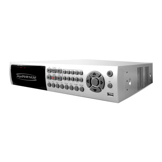
Operational Guide 2. Product Description 2-1. Front Panel Figure 2.1. Front Panel Table 2.1.1. Indication Lamps Name Description LED illuminates when system accesses hard disk. LED illuminates when system records video. ALARM LED illuminates when alarm sensor(s) is/are triggered, or *detects video motion (*must configure video motion detector first). - Page 10 Operational Guide Press to start auto sequencing in full or quad display modes. Press to select audio mode. AUDIO Disable or Mute all 4 channels or selected channels only. Press to initiate PTZ control Press to launch SETUP menu.
-
Page 11: Rear Panel
Operational Guide 2-2. Rear Panel Figure 2.2. Rear Panel Table 2.2.1. Connectors and switches at rear panel Name Function 16 BNC connectors for video input. VIDEO IN Connect camera output to Video-in (NTSC/PAL) 16 BNC connectors for video output.(loop back) -
Page 12: Remote Controller
Operational Guide POWER Connector for AC115-230V power cable. SWITCHES TEST For future use MyDVR1630/930 must reboot after changing Reserved switch positions! Set to ON when VGA monitor is used. Set to ON when video is PAL 2-3. Remote Controller... -
Page 13: Alphabet Input With Remote Controller
Operational Guide 2-3-1. Alphabet input with Remote controller Numeric key pads of the remote controller can be used to enter alphabet, when alphabet input is needed in parameter setting. The scheme follows that of the key pad of telephone. -
Page 14: Getting Started - Setting Up The Dvr
Operational Guide 3. Getting Started – Setting Up the DVR The following sections detail the initial setup of the DVR 3-1. Setup – Main Screen Pressing the Setup button prompts the user for password entry. The default password is 1111. Input the default password by pressing the Up button 4 times, followed by the SELECT button. -
Page 15: Setup - Live
Operational Guide 3-2. Setup – Live - Used for setting up the live display mode. Navigate through menu items using the Up/Down buttons. Change the values using the Left/Right buttons Figure 3.2.1. Live mode setup screen Table 3.2.1. Menu items in LIVE mode setup... -
Page 16: Setup - Recording Mode
Operational Guide BRIGHTNESS Brightness value for the specified channel Contrast value for the specified channel CONTRAST Hue value for the specified channel SATURATION Saturation value for the specified channel 3-3. Setup – Recording Mode - Controls video recording attributes Navigate through the menu items using Up/Down buttons. -
Page 17: Setting Up Motion Zones
Operational Guide shows the maximum frame rate for NTSC/PAL video. Resolution Max. Frame Rate 320x240 120/100 FPS 704x240 30 FPS 704x480 30 FPS Configure the recording quality for a specified channel. QUALITY Netork, Standard, High, Super, Ultra. Video quality is the best for “Ultra” (Network quality is designed for very low upload bandwidth conditions (i.e. -
Page 18: Record Schedule
Operational Guide Figure 3.3.2. Motion Zone selection screen 3-3-2. Record Schedule - Records video based on a defined schedule. The following table (3.3.1) defines button functions within this menu. Use the four Direction keys and the Select key to navigate through the menu system. - Page 19 Operational Guide Table 3.3.1. Button functions in Recording time scheduling mode Button Function Use to set Continuous recording mode. F/REW Use to Disable recording setting. PLAY/PAUSE Use to enable Motion detection triggered recording. Use to enable Sensor triggered recording Move up in menu item.
-
Page 20: Setup - Device Mode
Operational Guide 3-4. Setup – Device Mode - Configures values for device settings. Navigate through each menu item by pressing the UP or DOWN arrow buttons. Change the value of an item by pressing the LEFT or RIGHT arrow buttons. -
Page 21: Alarm-Out
Operational Guide 3-4-1. ALARM-OUT Table 3.4.1.1 Menu item in ALARM-OUT Setup screen Item Description ALARM OUT Select alarm outputs from 1 to 8. Enable for up to 4 sensors out a total of 16. SENSOR IN Enable for up to 4 cameras out of a total of 16. - Page 22 Operational Guide manufacturer you wish to control. If the camera uses a specific camera ID, select the camera ID by using the Left or Right buttons. Table 3.4.2.1. Menu item in PTZ Setup screen Item Description Select the channel number for the PTZ device setup.
-
Page 23: Spot-Out
Operational Guide 3-4-3. SPOT-OUT Table 3.4.3.1. Menu items in SPOT-OUT Setup screen Item Description SPOT TYPE Configure the display mode, either full or quad view for the spot monitor output. SPOT ON EVENT Enable/disable spot monitor upon events. SPOT EVENT Set the dwell time for spot event monitor from 1 to 10 seconds. -
Page 24: Setup - System Mode
Operational Guide 3-5. Setup – System Mode - Configures system parameters Navigate through the menu items by pressing the UP or DOWN arrow buttons. Change the value of menu items by pressing the LEFT or RIGHT arrow buttons and UP or DOWN buttons. - Page 25 Operational Guide Table 3.5.1. Menu items in System Setup screen Item Description DVR ID Defines the system name. Navigate through the position for each alphanumeric character by using the left and right buttons. Up/down buttons change characters. Displays system information: DESCRIPTION Firmware Version, Storage Size, IP Address, and MAC Address.
- Page 26 Operational Guide Figure 3.5.3. DVR information display screen Preliminary Content subject to change without notice.
-
Page 27: Setup - Security Mode
Operational Guide Figure 3.5.4.Set Date & Time setup screen Table 3.5.4. Menu items in Date & Time setup SET DATE&TIME Warning Changing this setting initiates a system reboot. date and time. After changing, press the SEL button and select CONFIRM. - Page 28 Operational Guide Figure 3.6.1. Security setup screen Table 3.6.1. Menu Items in Security Setup Screen Item Description ADMIN PASSWORD Sets the administrator password. Once selected, the DVR will prompt for the current password and new password. Follow the prompts. The password numbers 1, 2, 3 and 4 can be input by using direction keys.
-
Page 29: Setup - Network Mode
Operational Guide 3-7. Setup – Network Mode - Configures network parameters used for remote clients that connect to the DVR over a network or other network features. If you do not understand the following settings, consult your network administrator. -
Page 30: Ports
Operational Guide Event Alarm Setting to “ON” sends an e-mail upon an alarm event. Input the designated recipient’s address. Mail Address Mail Server Name Enter the name of your SMTP server. Enter your SMTP server user ID. Enter your SMTP server password. -
Page 31: Network Types
Operational Guide port numbers, unless other IP sharing devices sit in-between the client and the DVRs. To access the DVR, you must have the following information: Table 3.7.1.1 Information needed for network access When accessing from the same LAN When accessing from outside the LAN DVR’s IP address... -
Page 32: Setup - Storage Mode
IP address for myDVR. Some ISPs block some ports commonly used for streaming video. If your ISP blocks the default port, simply change the port number to an unblocked port. See the iCanTek technical support web page for additional help trouble shooting blocked ports. -
Page 33: Saving Setup
Operational Guide Figure 3.8.1. Storage setup screen Table 3.8.1. Menus in Storage setup Item Description Overwrites oldest existing video when the hard drive is full. OVERWRITE Formats the hard disk drive. FORMAT DISK INFO Displays HDD/s disk information. Loads DVR set up parameters from the USB memory. -
Page 34: Local Viewing
Operational Guide 4. Local Viewing 4-1. Live Window Video from connected cameras are displayed on the Live Setup configuration screen. Symbols indicate DVR status. Refer to Table 4.1.1 for a legend. Figure 4.1.1. Live window Table 4.1.1. Indicator ICONS in Live window... - Page 35 Operational Guide Indicates Audio status, enabled/disabled. Indicates Locked DVR. Table 4.1.2. Button functions in Live window Button Description SETUP Launches SETUP menu. Enables/disables automatic sequential switching in full or quad modes. Quad mode also follows these settings.. Launches the SEARCH window.
-
Page 36: Search Window
Operational Guide 4-2. SEARCH Window Press PLAY/PAUSE button to launch the search menu. The screen shot shown in Figure 4.2.1 pops up. Select either “EVENT SEARCH” or “TIMELINE SEARCH” to initiate a search for recorded video. The other two menu fields are used to display the log data (LOG), or archived data for storage via the USB (ARCHIVE). - Page 37 Operational Guide Figure 4.2.2. Search mode screen Figure 4.2.3. Search mode screen Preliminary Content subject to change without notice.
- Page 38 Operational Guide Searching for an event: 1. Select a date to begin searching. Use the LEFT, RIGHT and UP and DOWN buttons to navigate through dates. 2. Press the SEL button to move to the CHANNEL selector. 3. Use the LEFT or RIGHT buttons to change the channel selection from ALL to any of the 16/9 available channels.
-
Page 39: Play Mode
Operational Guide 4-3. Play mode During recorded event playback, myDVR switches from the SEARCH screen to PLAY mode. To return to the SEARCH LIST press the ESC button. Figure 4.3.1. Play mode screen Table 4.3.1. Button functions in Play mode... -
Page 40: Ptz Control
Operational Guide playback speed. Playback speed is indicated as +1X, +2X, +4X, and +8X for normal, twice, 4 and 8 times of the regular speed, annunciated in the bottom right hand corner of the screen. Use to select channels 1 thru 4 in full screen mode. Change to Direction Buttons quad, or 9 split display by using the LEFT or RIGHT buttons. - Page 41 Operational Guide ZOOM/FOCUS Select menu and use the Up/Down keys for zoom control. Left/Right keys control focus. Initialize Initializes the selected cameras. Preliminary Content subject to change without notice.
-
Page 42: Archiving Video Via Usb, Or Cdrw
Operational Guide 5. Archiving Video via USB, or CDRW It is a function of archiving a still image or video clip to USB storage, or CDRW. It is required to have captured data before the archiving. 5-1. Capturing images or video Capture still images in live mode or while playing back recorded video. -
Page 43: Transferring Still Images Or Video Into Usb Or Cdrw
Operational Guide or video captures the respective type of file to the hard disk. Insert a USB storage device. Select the type of storage device preferred, USB, or CDRW. myDVR converts the file to *. AVI file type and writes to the device selected. - Page 44 Operational Guide Figure 5.2.2. List of archived files The DivX, or comparable codec must be installed for proper playback. DivX codec may be downloaded from: http://www.divx.com/divx/download/ Preliminary Content subject to change without notice.
-
Page 45: Firmware Upgrade
Operational Guide 6. Firmware Upgrade 6-1. Preparing USB memory with upgrade firmware 1. Before upgrading the system, on your USB memory stick, create the following directory, E:\upgrade (E:\ is just an example, your drive letter may be different). 2. Copy the firmware file to the \upgrade folder. -
Page 46: Network Client - Remote Monitoring And Playback
Operational Guide 7. Network Client - Remote Monitoring and Playback 1. Install the MyNVR application to your PC. 2. Follow the appropriate instruction in the network setup instruction in section 3-7. 3. Connect the DVR to the Network via the Ethernet Port on the back panel. -
Page 47: Remote Set Up Of Mydvr
After completing all setup values, go to the “Save Setup” menu and press the SAVE button. The system will apply the settings and reboot. To protect your DVR from unauthorized use, iCanTek strongly recommends changing the User ID and Password. - Page 48 Operational Guide Figure 8.1. Live Control Setup Page Preliminary Content subject to change without notice.
- Page 49 Operational Guide Figure 8.2. Record Setup Page Figure 8.3. System Setup Page Preliminary Content subject to change without notice.
- Page 50 Operational Guide Figure 8.4. Device Setup Page Preliminary Content subject to change without notice.
- Page 51 Operational Guide Figure 8.5. Network Configuration Page Figure 8.6. Storage Setup Page Preliminary Content subject to change without notice.
- Page 52 Operational Guide Figure 8.7. Save Setup Page Preliminary Content subject to change without notice.
Need help?
Do you have a question about the myDVR1630 and is the answer not in the manual?
Questions and answers