Table of Contents
Advertisement
Advertisement
Table of Contents

Related Manuals for clare safe check 8


Summary of Contents for clare safe check 8
- Page 1 Instructions 309A553 August 2006 © 2004 Clare Instruments Issue 2...
-
Page 2: Table Of Contents
Contents Declaration of conformity Safety Chapter 1 - Introducing the Tester Introduction Your Electrical Safety Tester Chapter 2 - Using the Tester Switching on the Tester The Login Screen The Main Menu Selecting the Test Settings The Test Sequence Performing Manual Tests Entering Manual Mode Chapter 3 - Changing the Setup Configuring the Tester... - Page 3 Contents Chapter 5 - Interfacing Serial Port Parallel Port Barcodes Guard Switch Beacon Chapter 6 - Maintaining the Tester Cleaning the Tester User Maintenance Chapter 7 - Accessories Standard Accessories Optional Accessories Chapter 8 - Specification Appendix A - Purpose of Tests...
-
Page 4: Declaration Of Conformity
Declaration of Conformity Declaration of Conformity for the Clare Safe Check 8 Portable Appliance Tester Manufactured by: Seaward Electronic Ltd, Bracken Hill, South West Industrial Estate Peterlee, County Durham, SR8 2SW, England Millennium Statement This product is Millennium compliant, and conforms fully to the document BSI DISC PD2000-1. -
Page 5: Safety
Safety Note - Please read the following Safety Instructions before use ! Safety Precautions The manual contains specific warning and caution statements where they apply. A Warning will identify the conditions and actions that pose hazard(s) to the user. A caution will identify the conditions and actions that may damage the Tester. - Page 6 Safety Warning Due to the potential hazards associated with any electrical circuit it is important that the user is familiar with the instructions covering the capabilities and operation of this instrument. The user should ensure that all reasonable safety precautions are followed and if any doubt exists should seek advice before proceeding.
-
Page 7: Chapter 1 - Introducing The Tester
Introduction Introduction The Clare Safe Check 8 Electrical Safety Tester is a powerful tool to assist in the analysis of the safety of portable electrical and electronic equipment. A range of tests are provided, with innovative features to aid the various test situations. -
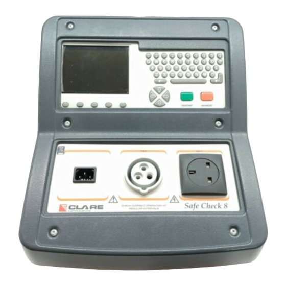
Page 8: Your Electrical Safety Tester
Your Electrical Safety Tester The Display The Safe Check 8 is equipped with a 320 x 240 1/4 VGA Graphical Liquid Crystal Display (LCD). The LCD graphic interface has been designed to give clear feedback on the status of the tester and facilitate a simple intuitive menu system that guides the user through each stage in the testing process. - Page 9 The functions will reflect the most likely actions to be taken from the point of each screen. The Safe Check 8 also has the ability to use non-standard characters, which can be displayed by pressing the ‘Symbols’ key during text entry. Simply use the cursor keys to highlight the required character and press the Green button.
-
Page 10: Chapter 2 - Using The Tester
Switching on the tester Switching on the tester The Tester is supplied with a moulded 3 pin plug to ensure that it is safely wired and ready to go from receipt. The Tester must be powered by a 230V or 110V supply, which includes a protective Earth connection, via a correctly wired 3 pin plug &... -
Page 11: The Login Screen
The Login Screen If there are any problems with the supply, the Tester will give a warning indicating the nature of the problem. There are two possible warnings: 1 - Phase / Neutral reversed As the message suggests, this means that the Tester has detected that the Line &... -
Page 12: The Main Menu
The Main Menu The Cursor keys can be used as described above to navigate though the Login Menu. In addition to the Login Menu, the screen has two fast key functions - SYMBOLS and OK. The SYMBOLS command allows the user access to additional characters such as mathematical symbols and letters with accents. -
Page 13: Selecting The Test Settings
Selecting The Test Settings As can be seen, there are three main options, plus a fast key command to return to the Login screen. At this stage, we are only interested in the new test option since the memory options and set-up selections will be described separately in the later chapters of this manual. - Page 14 Selecting The Test Settings Earth Bond Test Current = 25A Duration = 2 seconds Pass level = below 0.5Ω Line Short to Case Voltage = 40Vac Duration = 2 seconds Pass level = below 1mA Flash Test Voltage = 1250Vac Duration = 2 seconds Pass level = below 3mA Power/Leakage Test...
- Page 15 Selecting The Test Settings Flash Test Voltage = 2500Vac Duration = 2 seconds Pass level = below 2mA Power/Leakage Test Voltage = Supply voltage Duration = 5 seconds Power Pass level = Nominal >=4Ω Leakage Pass level = below 1mA C: POWER CORD TEST This test selection is for the testing of detachable power cords such that used by computers &...
-
Page 16: The Test Sequence
The Test Sequence Polarity Test Voltage = 40Vac Duration = 2 seconds Power Pass level = correct wiring All of these settings are factory preset for convenience, but can user defined as described in Chapter 3. As with all menus, to select a setting highlight it using the cursor keys and press YES or Enter. - Page 17 The Test Sequence 1: Visual Check The visual check feature is included to enable the user to record the fact that the unit has been physically inspected for defects. There are three main inspection points - case, lead & fuse. For each of these three inspection categories, the tester will prompt the user for confirmation of a pass or fail result.
- Page 18 The Test Sequence 3: Insulation Test If selected in the test settings, the Insulation Test will be performed. The test applies 250V or 500V to Live & Neutral with respect to Earth. The protective insulation between Live / Neutral and Earth is then measured and displayed in MΩ.
- Page 19 The Test Sequence Depending on test selection, the Flash test is performed at either 1250Vac or 2500Vac. For Metal Cased products, the test is performed at 1250Vac. The test voltage will be displayed at the top of the screen. If testing a Double Insulated product, use the Flash probe and apply it to a suitable test point on the product under test.
-
Page 20: Performing Manual Tests
Performing Manual Tests Print Results Selecting Print Results will cause the tester to print the results in the current print format. This setting will default to Roll Printer PASS / FAIL labels. Performing Manual Tests Manual mode provides the user with direct access to the tests. In this mode individual tests can be selected and performed. - Page 21 Performing Manual Tests Performing The Test Visual Check This test is performed in the same way as when performed during the standard automatic tests. Once the test is complete, the Manual Test Selection menu will reappear. Earth Bond Test There are two areas of interest in the test screens. The areas are shown in the following screen shot: The cursor keys can be used to change the value of each of the parameters.
- Page 22 Performing Manual Tests Once the settings on screen are correct, press YES/START to perform the test. Once the test is complete, the tester will return to this screen to allow another test to be performed if required. If no more Earth bond tests are required for that product then press NO/ABORT at this stage and the tester will return to the Manual Test Selection menu.
- Page 23 Performing Manual Tests Leakage Test This test should only be performed after ensuring that no hazard will result from the product function e.g. spinning drill etc. Once the settings on screen are correct, press YES/START to perform the test. Once the test is complete, the tester will return to this screen to allow another test to be performed if required.
-
Page 24: Chapter 3 - Changing The Setup
Configuring The Tester Configuring The Tester Although the tester has been designed to be used without the need to make any changes to the settings, it is possible to tailor the settings to suit the individual application. The settings include user preferences, automatic printing of labels and disabling help screens etc. - Page 25 How to use Setup Edit Test Settings This allows the user to add, modify, remove or confirm test settings that can then be selected during automatic testing. SELECT TEST SETTING A. 240V CLASS 1 B. 240V CLASS 2 C. 240V POWER CORD D.
-
Page 26: Test Parameters
How to use Setup Name Each test sequence is given a name. This is to help the user when selecting test sequences during automatic testing. When Name is highlighted press the Enter button, then use the keyboard to enter a new name for the Test Sequence (of up to 15 characters) and press Enter to confirm. -
Page 27: Editing The User Settings
How to use Setup Store Settings Use the cursor keys to highlight the OK and press Enter or select the OK Fast key to save the settings and return to the previous menu. Pressing the Red Button will abort all of the changes made and return to the previous menu. - Page 28 How to use Setup Novice User Selects the User level as a NOVICE user. This will cause Help screens to be displayed prior to every test. Advanced User Selects the user level as an ADVANCED user. No Help will be displayed before each test automatically.
-
Page 29: Changing Date & Time
How to use Setup Saving User Settings In the EDIT USER SETTINGS, highlight OK and press the Enter button or select the OK Fast key. The user settings will then be saved. Change Date / Time -------SET DATE AND TIME------- 01/08/2002 15:30 This option allows the user to change the Date and Time. -
Page 30: Mains Polarity On Power Tests
Safe Check 8 is powered. AUTO CORRECTED - perform the power tests with the mains correct polarity even if the Safe Check 8 is powered from a socket, which has the mains polarity, reversed. INPUT & REVERSED - this option will perform two power tests for every one selected, one with the correct mains polarity and one with the reverse mains polarity. -
Page 31: Choosing The Roll Printer
Press the Red button to abort any changes made. Factory Settings It is possible to reset the Safe Check 8 to the settings which were configured from new. This option will first ask you if you are sure, select Yes to reset or No to abort. -
Page 32: Memory Options Menu
How to use the Memory How to use the Memory To use the memory tests and functions, use the cursor keys to highlight the MEMORY OPTIONS on the Main Menu and press Enter to display the following menu: - --------MEMORY OPTIONS-------- VIEW MEMORY USED PERFORM MEMORY TEST DELETE SINGLE APPLIANCE... -
Page 33: Delete Single Record
How to use the Memory Once the PERFORM MEMORY TEST option is highlighted press the enter button. The memory test checks all of the appliance results against their checksums. If the test passes then no action is taken. If the test fails then the Memory checksum requires updating. -
Page 34: Chapter 4 - Tips And Troubleshooting
How to use Help How to use Help The Tester is provided with an on-line help function, which can be called up when the test screens are displayed, by pressing the HELP fast key. Each test will have three or four help pages depending on information content. -
Page 35: Power-On Self Tests
Earth on the Tester connection is secure. If all the above is checked OK, then the Safe Check 8 may be faulty. Contact your Seaward Agent for repair. The unit then completes an internal check. If any faults are found... -
Page 36: Safety Tests During Operation
Safety Tests during operation --------------------WARNING-------------------- INTERNAL RELAY FAULT.CANNOT PROCEED. If this message is displayed then the Safe Check 8 is faulty and should be returned to your Clare agent for repair. Safety Tests during operation The Tester performs self-tests during normal operation. An internal Earth Bond test and a low voltage test are performed prior to applying mains power to any EUT (including Leakage tests). -
Page 37: Multiple Earth Connections
This has previously needed the additional Earth connections to be isolated. The Safe Check 8 tester is capable of testing Earth connections in the presence of additional Earth paths. This is done automatically by performing a point-to-point measurement of the Earth connection, and measurement of the differential leakage current, rather than the Earth lead current. -
Page 38: Chapter 5 - Interfacing
Serial Port The Tester provides two interfacing ports: - Serial Port The serial port uses a standard 9-way D-type connector Description N.C. N.C. N.C. Baud Rate: 9600, 19200, 28800 (selectable) Start Bits: Data Bits Stop Bits: Parity: None Inter-character Delay: 20ms The Serial Port is for connection to a PC, Printer, Barcode Reader, Modem, or Brain Cell Reader. -
Page 39: Barcodes
Barcodes Barcodes Barcode Scanner Specification The Safe Check 8 Tester can be used with barcodes and barcode scanners, readers or wands compatible with other Seaward PAT testers. These connect to the serial (RS232) connector. The required barcode reader / scanner configuration is as follows: -... -
Page 40: Cleaning The Tester
Cleaning the Tester Cleaning the Tester The Tester case can be cleaned with a damp cloth, with if necessary, a small amount of mild detergent. Prevent excessive moisture around the socket panel or in the lead storage area. Do not allow liquid inside the Tester, or near the sockets panel. Do not use abrasives, solvents, or alcohol. - Page 41 User Maintenance Seaward Electronic Ltd Bracken Hill South West Industrial Estate Peterlee Co Durham SR8 2SW Tel: +44 (0)191 5863511 Fax: +44 (0)191 5860227...
-
Page 42: Chapter 7 - Accessories
Standard Accessories A series of standard and optional accessories are available for the Clare Safe Check 8 Tester. The standard accessories are supplied with the Tester. Standard Accessories Accessory Part Number Earth Bond Test Lead 249A908 Flash Probe 43B679 Instruction Manual... -
Page 43: Chapter 8 - Specification
Specification Specification Earth Bond Test Test Voltage 6V nominal (no load) Test Current 4A, 10A, 25A (into s/c load) Range 40mΩ - 19.99Ω Resolution 1mΩ Accuracy +/- 5% +/- 2 digits Pass Levels user selectable Earth Screen Test (IT Earth Bond Test) Test Voltage 100mV nominal (no load) Test Current... - Page 44 Specification Flash Test (CLASS 1) Test Voltage 1.25kV a.c Display Range 0.1 - 10 mA a.c. Resolution 0.01mA Accuracy +/- 5% +/- 2 digits Pass Levels selectable up to 10mA Flash Test (CLASS2) Test Voltage 2.5kV a.c Display Range 0.1 - 10 mA a.c. Resolution 0.01mA Accuracy...
- Page 45 Specification Environmental Operating 0ºC to 40ºC (non condensing) Storage 10ºC to 50ºC (non condensing) Maximum RH Supply Rating 110V - 230V +/- 6% 50/60Hz Max Output Current...
-
Page 46: Appendix A Purpose Of Tests
Appendix A Purpose of Tests Earth Bond Test This test is to ensure that the connection between the Earth pin in the mains plug of the appliance and the metal casing of the appliance is satisfactory and of sufficiently low resistance. A selectable test current is applied between the Earth pin of the mains supply plug and the Earth Bond test lead clip. - Page 47 Appendix A Purpose of Tests For appliances which incorporate over-voltage protection, a 250V DC test voltage is provided to allow a reading to be taken without the protection devices generating a false failure. Short to Case Test The Short to Case test applies a nominal voltage of 40V AC RMS to the appliance and is applied between the Earth pin and both the live and neutral pins of the supply plug.
- Page 48 Appendix A Purpose of Tests IEC Lead Test This test confirms the electrical safety of 230V IEC leads. The IEC test performs a continuity and polarity check on the Live and Neutral conductors and confirming that there are no breaks or cross wiring in these conductors.
- Page 49 Appendix A Purpose of Tests Leakage Test The Leakage Test shows the current being lost through Leakage as the difference in the currents flowing in the Live and the Neutral conductors. This difference is the total leakage away from the appliance, and is generally equivalent to the current flow through the Earth lead of the appliance, and displays the result in milliamps (mA).
Need help?
Do you have a question about the safe check 8 and is the answer not in the manual?
Questions and answers