Table of Contents
Advertisement
Quick Links
Advertisement
Table of Contents

Subscribe to Our Youtube Channel
Summary of Contents for Swann DRS SERIES
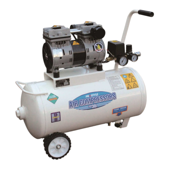
- Page 1 DRS SERIES OIL-LESS AIR COMPRESSOR OPERATION MANUAL...
- Page 2 PREFACE Thank you for purchasing a air compressor. This manual introduces our DRS Series air-cooled oil-less air compressors to the user all the information required to install, commission and operate compressors and carry out the regular schedules for servicing and maintenance which ensure the most efficient and trouble-free operation while the compressor begins to run.
-
Page 3: Table Of Contents
INDEX Features------------------------------------------------------3 Description & function-------------------------------------4 III. Installation and precautions-------------------------------5 IV. Operation----------------------------------------------------6 Maintenance-------------------------------------------------6 VI. Trouble shooting--------------------------------------------8 APPENDIX I. Air compressor configuration----------------------10 APPENDIX II. Electric circuit diagram-----------------------11 APPENDIX III. Air flow diagram-----------------------------12... -
Page 4: Features
I. Features 1. DRS series air compressor pump 1-1. High quality components. Reliable and easy maintenance. 1-2. Low noise, high efficiency filter to reduce noise. 1-3. Equipped with anti-vibration pad to achieve low vibration. 1-4. High efficient motor with built-in over-heat protector inside. -
Page 5: Description & Function
II. Description & function Name Description Name Description Drain water when tank pressure under 1 kg/cm Pressure control, Pressure Drain valve Close—clockwise Leveling rod to ON/OFF switch Open—counter clockwise the unit manually. Tank Motor Built-in over-heat protection. pressure Indicate air tank pressure. gauge Safety Tank over-pressure... -
Page 6: Installation And Precautions
III. Installation and precautions 1. Installation essentials 1-1. Please install the unit in position where it is easy to do maintenance and good ventilation. 1-2. Do not install in damp or dusty places. 1-3. Install on flat and firm ground to prevent from slipping. -
Page 7: Operation
Please power off the unit and check. Restart the unit after trouble-shooting. IV. Operation 1: : : : Check before start 1-1. Make sure if power source and electrical connections comply with local electrical regulations, equipped with NFB (Non Fuse Breaker) and earth wiring. - Page 8 1-5. Check if voltage & current of the power supply to the motor are normal. 1-6. Check and clean impurities from inlet filter element every month (300 hours). 2: : : : Periodically maintenance Item Weekl y Monthl y Yearl y 2 Year Air tank drain ○...
-
Page 9: Trouble Shooting
VI. Trouble shooting Action Troubles Possible Causes Check Repair Renew Compression ring is worn-out Cylinder is worn-out Valve ass y. Or gas kets leaking Pressure Drain val ve leaking cannot be raised Intake air filter is blocked properly Pipe leaking Defective pressure gauge Solenoid val ve leaking Safety val ve leaking... - Page 10 Action Troubles Possible Causes Check Repair Renew Low voltage Hi gh ambient temperat ure Ventilation blocked Valve ass y. broken Ab n o r m a l Running Bearing broken t e mp e r a t u r e Fault motor Connecting rod loose Crankshaft loose...
-
Page 11: Appendix I. Air Compressor Configuration
APPENDIX I. Air compressor configuration Description Description Compressor unit Pressure gauge Air receiver Anti-vibration pads Wheel Hose Safety valve assembly Solenoid valve Check valve assembly Pressure regulator Drain valve assembly Pressure gauge (Outlet Pressure) Pressure switch Quick coupling (Air outlet) Cable with plug... -
Page 12: Appendix Ii. Electric Circuit Diagram
APPENDIX II. Electric circuit diagram Symbol Description Pressure switch Solenoid valve Compressor motor Motor capacitor Over-heat protector Earth wire Electric cord L1,L2... -
Page 13: Appendix Iii. Air Flow Diagram
APPENDIX III. Air flow diagram PG.1 PG.2 COMP. 空氣 空氣 入口 出口 SOL. Description Description Symbol Symbol Inlet air filter Ssfety valve Motor Pressure switch PG.1 COMP Compressor unit Drain valve Solenoid valve Ball valve SOL. Check valve Pressure regulator Air tank Pressure gauge (Outlet) PG.2... - Page 14 TONG CHENG IRON WORKS CO., LTD. No.16 Ta Chin St., Sec.2 ,Taichung, Taiwan. Tel: 886-4-22612135 Fax: 886-4-22628246 Web site: www.swanair.com.tw E-mail: swantc@swanair.com.tw M01865H300E(A)
Need help?
Do you have a question about the DRS SERIES and is the answer not in the manual?
Questions and answers