Table of Contents
Advertisement
Advertisement
Table of Contents

Related Manuals for SIFANG CSC-1321

Summary of Contents for SIFANG CSC-1321
- Page 1 CSC-1321 Gateway User Guide...
- Page 2 CSC-1321 Gateway User Guide Compiled: Lv Hongchang Checked: Wu Fangying Yu Bin Standardized: Li Lianchang Inspected: ...
- Page 3 ® is registered trademark of Beijing Sifang Automation Co., Ltd. We reserve all rights to this document, even in the event that a patent is issued and a different commercial proprietary right is registered. Improper use, in particular reproduction and dissemination to third parties, is not permitted.
-
Page 4: Safety Information
Preface Safety information Strictly follow the company and international safety regulations. Working in a high voltage environment requires serious approch to aviod human injuries and damage to equipment Do not touch any circuitry during operation. Potentially lethal voltages and currents are present Avoid to touching the circuitry when covers are removed. - Page 5 Handling modules with a conductive wrist strap connected to protective earth and on an antistatic surface. Electrostatic discharge may cause damage to the module due to electronic circuits are sensitive to this phenomenon Do not connect live wires to the Gateway, internal circuitry may be damaged When replacing modules using a conductive wrist strap connected to protective earth.
-
Page 6: Table Of Contents
Contents Chapter 1 Opening Inspection...................... 8 Chapter 2 Installation and commissioning .................. 1 0 1 Installation ............................ 1 1 2 Inspection before powering on .................... 1 2 3 Insulation resistance measurement .................... 1 3 4 Power-on inspection of device ..................... 1 4 Chapter 3 ... -
Page 8: Chapter 1 Opening Inspection
Chapter 1 Opening Inspection Chapter 1 Opening Inspection About this chapter This chapter describes open package inspection of Gateway. ... - Page 9 Chapter 1 Opening Inspection 1 After opening the package, check whether the device appearance is intact without any damage. 2 Check whether the certificate of compliance, supporting documents, accessories and spare parts of the device are consistent with the order requirements, whether the description, name and quantity are consistent with that specified in the packing list and whether the device is complete.
-
Page 10: Chapter 2 Installation And Commissioning
Chapter 2 Installation and commissioning Chapter 2 Installation and commissioning About this chapter This chapter describes installation of Gateway and inspection before and after Gateway is energized. ... -
Page 11: Installation
Chapter 2 Installation and commissioning 1 Installation 1 The fixing device shall be fastened to the panel (cabinet) firmly and the coupling screws of the device shall be tightened. 2 The device grounding shall be of reliable connection to the panel (cabinet) grounding with grounding wire and grounding busbar and system. -
Page 12: Inspection Before Powering
Chapter 2 Installation and commissioning Inspection before powering on (a) Pull out all module and check whether the mechanical parts and components on the plug-ion are loose and drop one by one, whether there is mechanical damage and whether the wiring is firm; (b) Check whether module connectors are in place and whether the locking is reliable;... -
Page 13: Insulation Resistance Measurement
Chapter 2 Installation and commissioning Insulation resistance measurement The insulation resistance between circuits detected with magneto-ohmmeter with an open-circuit voltage of 500V in accordance with table 1 shall not be less than 100MΩ. Group A: power circuit terminal 220V+ and 220V- (or 110V+ and 110V-) of power terminal Group B: Binary input and public terminal 13-16 of binary input/output... -
Page 14: Power-On Inspection Of Device
Chapter 2 Installation and commissioning Power-on inspection of device After powering on the device, check according to the following steps: (a) LCD displays welcome screen and then enter normal display without any alarm information; (b) LED indicator is normal and the accident, alarm and communication interrupt indicators are not on;... -
Page 15: Chapter 3 Description Of Device Terminal
Description of device terminal Chapter 3 Description of device terminal About this chapter This chapter describes modules and terminal definition of Gateway. ... -
Page 16: Main Cpu Module
Description of device terminal 1 Main CPU Module It is DB9 serial port above the main CPU-N module and Ethernet port below such module. The Ethernet ports are 4 Ethernet RJ45 ports, which are Ethernet 1, 2, 3 and 4 in order from top to bottom. ... -
Page 17: Ethernet Module
Description of device terminal 2 Ethernet Module The external terminal of -N type Ethernet module is same with that of -N type main CPU module. ... -
Page 18: Serial Port Module
Description of device terminal Serial port Module The serial port module terminal is green 20-wire Phoenix terminal, which is for the use of RS232 and RS485 of 6 serial ports and the common terminal of two methods shall be selected by dialing up or jumper on the panel. See table 2 for the terminal definition. -
Page 19: Binary Input/Output Module
Description of device terminal Binary input/output Module The binary input/output module terminal is green 20-wire Phoenix terminal and ten-way binary inputs and two-way binary outputs are provided. See table 4 for the terminal definition. Table 4 Binary input/output module terminal definition description Serial No. -
Page 20: Time Synchronization
Table 6 Address setting range of dial switch J12 Time b8 b7 b6 b5 b4 b3 b2 b1 Synchronous Remarks synchroniz clock type ation method Serial port Serial port Sifang pulse connecting time SN-1 synchroniz Serial port Wave ation mode connecting electricity... - Page 21 Description of device terminal The time synchronization module terminal is green 6-wire Phoenix terminal, supporting GPS pulse time synchronization and IRIG-B time synchronization. See table 7 for the terminal definition. Table 7 Time synchronization module terminal definition description Serial No. Mark IRIG-B pulse time IRIG-B +...
- Page 22 Description of device terminal IRIG-B level time B_DC B_DC B_DC synchronization GPS time synchronization RS232 serial port GPS time synchronization RS485 serial port The “B_C” and “GPS” marked in above table are the mark of jumper position and there is clear mark near the corresponding jumper on the hardware board of module.
-
Page 23: Power Module
Description of device terminal 6 Power Module There are 2 kinds of power module, one supports 220V AC/DC input and the other supports 110V DC input. The terminal is green 8-wire Phoenix terminal. See table 9 for the terminal definition. Table 9 Power module terminal definition description Serial No. -
Page 24: Chapter 4 Human-Machine Interface And Its Operation
Human-machine interface and its operation Chapter 4 Human-machine interface and its operation About this chapter This chapter describes HMI, menu operation and menu display of Gateway. -
Page 25: Front Layout Of The Device
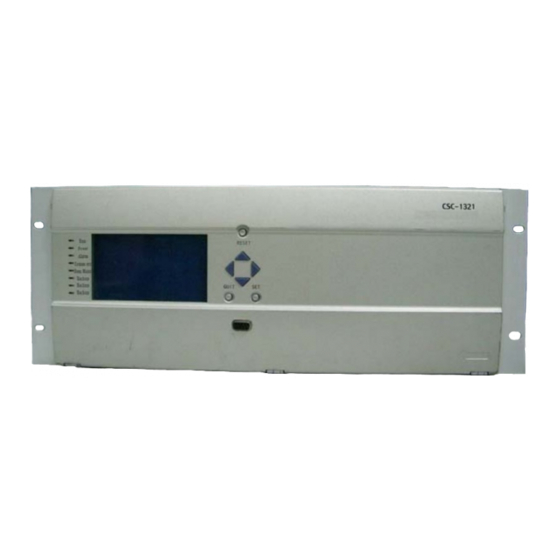
Front layout of the device Figure 1 Front layout of CSC-1321 series devices Explanation of elements on the panel: There are eight indicators on the left panel, among which the front five have clear definitions and the rest three are for reservation. The... -
Page 26: Display Under Normal Operation
…… …… Figure 2 CSC-1321 normal operation recycling display interface The top line of the interface is time which indicates the local time to seconds. Figure on the right side is the notion for pages. For example: “1/3” means that there are totally 3 pages in display and the current page is the first one. -
Page 27: Menu And Its Operation
Human-machine interface and its operation Menu and its operation Menu discription Description for menu at all levels shall refer to table 10. Table 10 Function of menu at all levels Main menu First level Second level Third Fourth Function menu menu level level... - Page 28 Human-machine interface and its operation Main menu First level Second level Third Fourth Function menu menu level level description menu menu Restart module module1 Start module …… panel All module Display software VersionInfo version information of the device protocol module name Name list of DeviceSettg...
- Page 29 Human-machine interface and its operation Main menu First level Second level Third Fourth Function menu menu level level description menu menu Set the effectiveness of accident, alarm, Event Enable communication outage and remote Light Control maintenance lights Alarm Enable Comm Enable Maintain Enable GPS Enable Set the information of...
-
Page 30: Communication Status
ValueSettg TimeSettg EventInfo LocalSettg LCD.Settg 语言(Language) Figure 3 CSC-1321 main menu display interface 3.1 Operating condition There are four first level menus in operating condition: communication status, function setting, input and output, restart module and version information. CommState Functiong Set DI&DO... - Page 31 Default Sort Active Sort Inactive Sort Figure 5 CSC-1321 sorting modes selecting interface After selecting a view mode, press SET button to display communication status of each module in line with sorting mode, and to display communication status of each configured devices. The interface is as follows:...
- Page 32 Human-machine interface and its operation module14 module 15 Figure 8 CSC-1321 display interface for input and output module selecting Select module 14, press SET button to view each of the input and output status of it: 1 / 1 [1-3-1-1] DI:1 2...
-
Page 33: Version Information
Human-machine interface and its operation Figure 11 CSC-1321 binary output actuator display interface 3.1.4 Version information Move the cursor to “Version information” menu item on operating condition menu; press SET button to display current software version number. It will display the interface as follows: [1-5] Software version: 01.20.00... -
Page 34: Protocol Configuration
This interface is for reference only, and no modification of the protocol can be made. 3.2.2 Channel Configuration CSC-1321 system supports many types of channels, each with a different channel configuration interface. ◆ Serial port configuration Interface of serial port configuration is shown as follows:... - Page 35 Mon port 2040 Tip; Modi need Manual reboot Figure 18 CSC-1321 Ethernet TCP server channel parameter display interface Move the cursor to the remote IP address, and press the up or down key to change its IP address. Move the cursor to the monitoring port, and press the up or down key to change port number.
- Page 36 Sending port 2040 Tip; Modi need Manual reboot Figure 19 CSC-1321 Ethernet TCP client-site channel parameters display interface Move the cursor to the connection port, and press the up or down key to alter the port number. Move the cursor to the remote IP address, and press the up or down key to change the IP address Then, press SET to confirm your modification.
-
Page 37: Time Setting
Time setting is to set the system clock and automatic time synchronization function. The interface is shown as follows: Modify Time Sync Time Figure 22 Interface of CSC-1321 time setting 3.3.1 Clock setting Move the cursor to “clock setting”, and press SET to enter the following... - Page 38 Set Sync Time Top:SET key to Confirm QUIT Key To Cancel Figure 24 CSC-1321 automatic time synchronization interface 3.4 Event Information As a submenu of event information, real-time information is a kind of information saved during the loop when the device is on power, while to be lost when the power is off.
- Page 39 Human-machine interface and its operation Fault event Alarm event Dig event Comm event Figure 26 CSC-1321 event information interface If only protection event and communication event are accessible and the other two items are disabled, interface of the menu is shown as follows: [4-1]...
- Page 40 Contrast Backlight time Figure 30 CSC-1321 LCD adjustment submenu interface 3.6.1 Display contrast Press SET while the cursor is at the display contrast menu of LCD adjustment to enter the interface of contrast settings, shown as follows:...
- Page 41 Setting Backlighting Time 05 Min Figure 32 Interface of LCD backlight time adjustment of CSC-1321 When in this interface, press the up or down key to adjust the backlight time within 00~99, which indicates the time limit of backlight. For example, if setting its value into 15, then the backlight would be out 15 minutes of no-operation;...
-
Page 42: Chapter 5 Operation And Maintenance
Chapter 5 Operation and Maintenance Chapter 5 Operation and Maintenance About this chapter This chapter describes operation and maintenance rules of Gateway ... - Page 43 Chapter 5 Operation and Maintenance Users shall compile their own operation and maintenance regulations based on their site conditions, and the following items listed are for reference only.
-
Page 44: Inspection Before Operation
Chapter 5 Operation and Maintenance 1 Inspection before operation a) The power indicator light on the front panel shall be on while turning on power. b) MMI is in normal function. c) Information of devices and channels displayed on the LCD are consistent with the actual situation. -
Page 45: Notes During Operation
Chapter 5 Operation and Maintenance 2 Notes during operation a) Under normal operating conditions, only the power indicator light on the front panel is on, and others are out. b) It is prohibited to press any of the key on panel at will while in operating. c) Any unauthorized modification to the configuration parameters of each channel is especially banned. -
Page 46: Common Failures And Countermeasures Irig-B Mode
Chapter 5 Operation and Maintenance Common failures and countermeasures IRIG-B mode Common failures, analysis of causes, and handling methods can be seen in Table11. Table 11 Common failures, causes, and handling methods Phenomena of Analysis of causes Handling methods Serial common failures work, Not reliable connection of... -
Page 47: Chapter 6 Transportation And Storage
Chapter 6 Transportation and storage Chapter 6 Transportation and storage About this chapter This chapter describes transportation and storage condition of Gateway ... - Page 48 Chapter 6 Transportation and storage This device shall be stored in a room with a temperature between -10℃~ +40 , relative humidity not more than 80%, and without any corrosion, ℃ flammable, or explosive hazardous materials in the surrounding air. Avoid violent vibration, impact and collision in transportation.
Need help?
Do you have a question about the CSC-1321 and is the answer not in the manual?
Questions and answers