Table of Contents
Advertisement
Quick Links
Advertisement
Table of Contents

Summary of Contents for Solartron Metrology SI7500
- Page 1 SI7500 ORBIT®-Digital Display Quick-start guide...
- Page 2 No part of this document may be reproduced or transmitted in any form or by means, electronic or mechanical, for any purpose, without the express permission of Solartron Metrology. © 2008 Solartron Metrology Ltd. All rights reserved. Orbit is a registered trademark of Solartron Metrology Ltd. All other brand names, product names or trademarks belong to their respective holders.
-
Page 3: Table Of Contents
Page About this Manual 5.8.2 Nominal With ++ Tolerances Safety Information 5.8.3 Nominal With -- Tolerances Introduction to the SI7500 5.8.4 Nominal With Fixed Limits Functionality Of The SI7500 SPC Configuration Navigating The Menu 5.9.1 UCL & LCL Or Xbar & r UCL & LCL Getting Started 5.10... -
Page 4: About This Manual
1.0 About this manual This document is not a complete user or installation guide, it is intended as an aid for new users to familiarise themselves with the SI7500 digital readout and it's functionality. For more detailed information on the SI7500 and it's functionality, please refer to the SI7500 User Manual (document number 502823), available from Solartron Metrology. -
Page 5: Safety Information
WARNING If the SI7500 falls from its mounting location, serious personal injury or damage to the equipment can result. Power cord and plug Do not locate the power cord where it can be walked on or will create a tripping hazard. Connect the 3-wire power plug to only a 3-wire grounded outlet. - Page 6 2.0 Safety Information (cont.) WARNING Always disconnect the power cord from the source of AC power before unplugging it from the SI7500 power connector. The AC voltage available at electrical outlets is extremely dangerous and can cause serious injury or death.
-
Page 7: Introduction To The Si7500
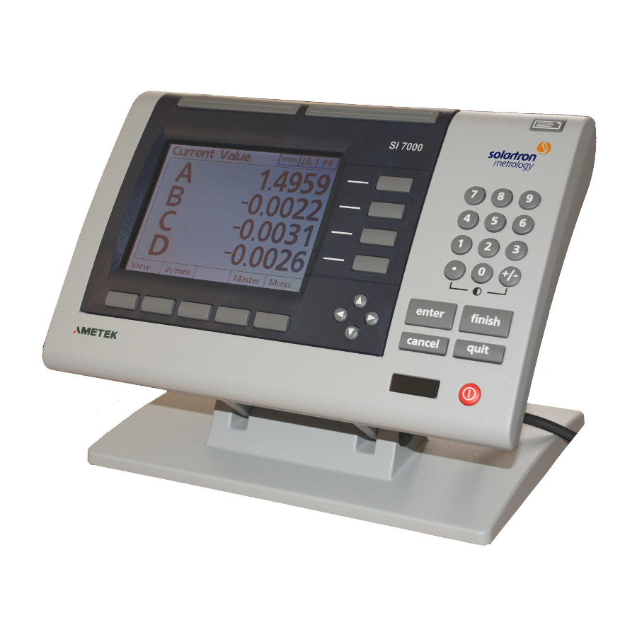
3.1 Functionality Of The SI7500 The SI7500 is a 16 channel advanced digital readout system for performing single or multipoint gauge measurements at very high levels of precision and accuracy. Dimensional inspection of components can be made using a range of Orbit transducers, encoders and other sensors as part of in-line production activities or final quality inspection. - Page 8 3.0 Introduction to the SI7500 (cont.) The SI7500's user interface screens include a digital readout of current values, bar and dial position value indicators, graphs of values, histograms of mea- surement statistics and tables of measurement and SPC data. Digital readout (DRO)
-
Page 9: Navigating The Menu
3.0 Introduction to the SI7500 (cont.) 3.2 Navigating The Menu The SI7500's menus are navigated by use of the keys displayed below: Dimension softkeys Softkeys are used to select options displayed at the bottom of the LCD screen. Numeric keypad... - Page 10 3.0 Introduction to the SI7500 (cont.) Actions such as navigating the Setup menu, configur- ing options and entering data are performed using a combination of the dimension & soft keys as well as the cursor, keypad and command keys (on this page).
-
Page 11: Getting Started
4.0 Getting started 4.1 Setup Procedure The flow chart below details the steps required to setup & begin using the SI7500. The next few sections in this guide will address each step in turn. Assign Orbit Connect Orbit Enter Supervisor Create a part &... -
Page 12: Connecting Orbit Hardware
Relay cable connector Parallel port Speaker jack The SI7500 can be connected to a network of up to 16 Orbit modules via the Orbit RS-485 port on the rear of the instrument. There is no USB port requirement for an extra power supply or Orbit Interface module. - Page 13 4.0 Getting started (cont.) The Orbit network and SI7500 should be connected in the way illustrated: Mixed probe capability Screened 9-way serial cable solartron so lartron Installation using T-CON ORBIT® Network of up to 16 modules Plug cable into RS-485 port at rear of unit (see * above) 4.0 Getting started (cont.)
-
Page 14: Setting Up The Si7500
5.1 Accessing The Setup Menu The SI7500's settings are modified in a setup menu. This is accessible from the default display screen (for factory settings, this is the DRO screen). After connecting the SI7500 to Orbit modules, as above, apply power to the unit. -
Page 15: Entering The Supervisor Password
5.0 Setting up the SI7500 (cont.) 5.2 Entering The Supervisor Password The SI7500's default settings include password protection of setup options. The supervisor password must be entered in order to modify setup menu options. From the About screen of the setup menu, navigate to the Supervisor screen using the cursor keys. -
Page 16: Assigning Orbit Modules To Channel Inputs
5.0 Setting up the SI7500 (cont.) 5.3 Assigning Orbit Modules To Channel Inputs The flow chart below outlines the procedure to follow in setting up & assigning Orbit modules to SI7500 channel inputs: Teach the Orbit Specify the Specify the Input... - Page 17 If the module Id has been successfully read, an on-screen message will appear notifying you of the successful reading of the Orbit module’s information. Repeat this process until the Id’s of all Orbit modules on the network are assigned to a particular SI7500 input channels. 5.0 Setting up the SI7500 (cont.)
-
Page 18: Parts, Dimensions, Formulas & Channels
Channel 2 Each Part can contain up to 16 "Dimensions", these are the features Channel 2 the fixture measures and are what will be displayed by SI7500 as measurement data. Dimensions are in turn composed of programmable "Formulas" ranging from direct channel inputs to complex mathematical formulae. -
Page 19: Creating A Part And Dimensions
5.6 Creating A Part And Dimensions The SI7500's factory settings' default Part is 0. To add or change to a different Part, enter the Dimensions screen of the Setup menu and highlight Part. With the Part field highlighted, the softkeys can be used to cycle between existing parts or to create new Parts. -
Page 20: Creating Formulas
This section of the guide will demonstrate how to setup a Formula, for more detailed information and a list of Formulas available on the SI7500, please refer to the SI7500 User Manual (document number 502823). - Page 21 5.0 Setting up the SI7500 (cont.) Press the down cursor arrow key to access the formula line. A red cursor will appear at the extreme left of the formula line. This cursor indicates the insertion point for any new formula function. Move the cursor to the desired insertion point by pressing Cursor keys.
-
Page 22: Limts & Tolerances
5.0 Setting up the SI7500 (cont.) 5.8 Limts & Tolerances The tolerances screen enables the speci fication of nominal values, upper/lower warnings, upper/lower limits and minimum/maximum bar graph levels for each dimension. Tolerance ranges are indicated numerically and by bands of color on the Current Value bar and dial screens. -
Page 23: Nominal With +/- Tolerances
5.0 Setting up the SI7500 (cont.) 5.8.1 Nominal With +/- Tolerances A nominal value is displayed between plus and minus tolerances. Acceptable range of values Press the +/-softkey to specify a nominal value with +/- tolerances, and then highlight the desired fields, and then use the numeric keypad to enter values. -
Page 24: Nominal With ++ Tolerances
5.0 Setting up the SI7500 (cont.) 5.8.2 Nominal With ++ Tolerances A nominal value is displayed with tolerances entirely on the plus side of nominal. To specify a range of tolerances above the nom inal value (+ Tolerance): 1. Press the +/- softkey 2. - Page 25 5.0 Setting up the SI7500 (cont.) 5.8.3 Nominal With -- Tolerances A nominal value is displayed with tolerances entirely on the minus side of nominal. To specify a range of tolerances below the nom inal value (- Tolerance): 1. Press the +/- softkey.
-
Page 26: Nominal With Fixed Limits
5.0 Setting up the SI7500 (cont.) 5.8.4 Nominal With Fixed Limits A nominal value is displayed between plus and minus fixed limits. To specify fixed limits above and below a nomi nal value: 1. Press the Limits softkey to specify a nomi nal value with fixed limits. -
Page 27: Spc Configuration
5.0 Setting up the SI7500 (cont.) 5.9 SPC Configuration The SPC screen con tains fields for speci fying statistical pro cess control parame ters including the Subgroup (sample) Size and Max (num ber of) subgroups stored, upper and lower mean control limits, and upper and lower range con trol limits. - Page 28 5.0 Setting up the SI7500 (cont.) Use the numeric key pad to enter the max imum number of points that will be plotted on graphs of subgroups for the specified part. NOTE: When there are fewer graph points specified than subgroups, the re-sulting dimension graphs might need to be scrolled to view all the subgroup data.
-
Page 29: Ucl & Lcl Or Xbar & R Ucl & Lcl
By default, the UCL and LCL fields dis play the upper and lower (acceptance) limits specified ear lier on the Tolerance setup screen. The limits are used by the SI7500 graphing soft ware to scale the value axis of SPC graphs. - Page 30 5.0 Setting up the SI7500 (cont.) The Xbar chart above shows upper and lower con trol limits that were entered into the Tolerance setup screen as upper and lower acceptance lim its prior to the collection of subgroup measure ment data. Once subgroup data has...
- Page 31 5.0 Setting up the SI7500 (cont.) The chart shown earlier indicates upper and lower control limits that were included as up per and lower acceptance limits prior to the col lection of subgroup measurement data. Once subgroup data has been collected, the upper and lower control limits can be simultaneously re calculated by highlighting either of the r con trol limit fields and pressing the Recalc softkey.
-
Page 32: Communications & Data Storage
The SI7500 can communicate measuring results by means of printing, storing or transmitting data through its onboard USB, RS-232 and Parallel ports. This section details the setup options for the RS-232 and USB ports. For a full list of the available options and their implementation, please refer to the SI7500 User Manual (document number 502823). - Page 33 5.0 Setting up the SI7500 (cont.) Parity: The Parity field is used to specify odd or even parity for error checking, or to omit parity error checking. Use the None, Odd or Even softkeys to specify parity error checking parameters.
-
Page 34: Usb Setup
USB flash drive. Files stored on flash drives are named DataN.txt by the SI7500 system, where N denotes the number of the data file. File type: The USB port data file type can be specified to replace existing files (of the same name) on the USB flash drive, append to the existing file or create new files that are auto-numbered sequentially in ascending order (Data1.txt, Data2.txt..DataN.txt). -
Page 35: Backing Up
It is recommended that after satisfactory configuration of the SI7500, a backup copy of the settings be taken. This can be done by saving the SI7500 settings as a file onto a USB flash memory stick. The settings can later be copied onto the same or another SI7500 to refresh a configuration or to speed the installation procedure in applications using several units. -
Page 36: Operation
6.1 Basic Operation The SI7500 is ideally used for static gauging, where parts are measured at rest. The gauging process itself can be semi or fully automated to varying degrees, as required. The flow chart below details a standard SI7500 measurement process: 6.2 Selecting A Part... -
Page 37: Establishing A Measurement Reference
6.3 Establishing A Measurement Reference Since all Orbit modules (with the exception of Analogue Input Modules) are pre-calibrated, typically only a single point needs to be calibrated on the SI7500 to define a reference position. Analogue Input Modules however require a full calibration to be performed by the SI7500 to derive the resolution of the instrument to which they are connected, instructions for this procedure can be found in chapter 5 of the SI7500 User Manual (document number 502823). -
Page 38: Conduct A Measurement
6.4 Conduct A Measurement The SI7500's DRO and Bar Graph screens display continuously updating Dimension values. The instrument is designed such that once a part is in place and Orbit Digital probes or other modules are reading appropriately, the currently displayed reading can be 'captured' and saved into the instrument's internal memory. -
Page 39: Send Or Report Results
6.6 Send Or Report Results Reports of current dimension values, screen views, stored measurement results or even SI7500 setup parameters can be printed, transmitted to a PC or PLC or saved to a USB flash memory stick simply by displaying the desired screen and pressing the "Print" key.
Need help?
Do you have a question about the SI7500 and is the answer not in the manual?
Questions and answers