Vertex VT4826+ Instruction Manual

Vertex VT4826+ Instruction Manual

Vt26+ series

Advertisement

1. INTRODUCTION
This manual contains information for the installation, operation and tuning of your Vertex
VT26+ series FUZZY ENHANCED auto-tuning microprocessor based controller.
controllers carry a two-year factory warranty. The VERTEX microprocessor controllers are
FUZZY ENHANCED "proportional + integral + derivative" (PID) controllers that come in a
variety of standard DIN sizes. The input is configurable and allows selection of inputs between
thermocouples and RTD's. You can also have 4~20 and other linear inputs as an option to be
specified when ordering the controller. When ordering your controller you can choose between
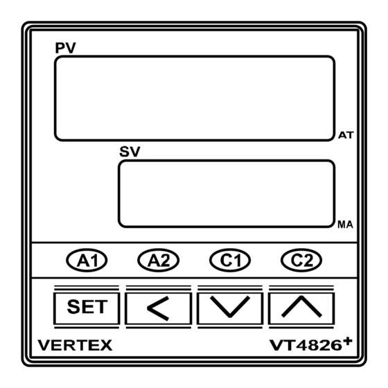
Relay, SSR, Heat / Cool, 4~20 mA or other output signals. They have dual displays that show
the input (measured temperature) in the top digital display and the required set point in the lower.
They all come standard with 2 alarm relay outputs. The controller boasts a comprehensive range
of other features that include a ramp, soft start with power limiting, auto/manual function and
comes standard with two configurable alarms. The controllers can be switched to manual and
can work as "time based ratio out-put controllers" in the event of thermocouple or input failures
taking place. There are other options you can choose including "retransmission" of either the PV
or SV or RS485 communications.

Features:

 T/C, RTD selectable from front panel or as optional extra Linear Input.
 Heating output Relay, SSR or analog to be chosen when ordering
 Fuzzy enhanced PID Control.
 Auto / Manual Bumpless Transfer.
 Two alarm outputs.
 Standby and Latch mode can be combined with 8 different alarm functions.
 Ramp to set point and soak functions.
 Soft- start function.
 Universal power supply : 100~240VAC, 50/60Hz. Or as optional extra 24
Vdc/Vac
 PV or SV Retransmission (Cannot have retransmission and Cooling output
together.
 RS-485 communication port as optional extra.(MODBUS RTU)
 Input sampling time 0.1 sec
2. IN A HURRY
These Vertex temperature controllers, although quiet sophisticated, can be equally very
simple to use. In its simplest form, all you need to do is install it and get the wiring right,
(YOU MUST READ CONNECTIONS AND WIRING section) turn it on, check that the
thermocouple type it is correct, (during the self test it will display the input type), make
sure it is reading more or less the right temperature, that the heating elements actually get
hot when the "C1" light is on and away you go. No need for laboriously reading this
manual and changing and setting all the parameters....Just turn it on and when the system
INSTRUCTION MANUAL FOR
VT48/96/72... 26+ FUZZY PID
These
1

Advertisement

Table of Contents
loading
Need help?

Need help?

Do you have a question about the VT4826+ and is the answer not in the manual?

Questions and answers

Subscribe to Our Youtube Channel

Summary of Contents for Vertex VT4826+

  • Page 1 INSTRUCTION MANUAL FOR VT48/96/72… 26+ FUZZY PID 1. INTRODUCTION This manual contains information for the installation, operation and tuning of your Vertex VT26+ series FUZZY ENHANCED auto-tuning microprocessor based controller. These controllers carry a two-year factory warranty. The VERTEX microprocessor controllers are FUZZY ENHANCED “proportional + integral + derivative”...
  • Page 2 To change the set point, first highlight the digit you wish to change using the sideways shift key and then use the up and down keys to make the change. Please search in YouTube for “Vertex VT26 Series” for more info about these controllers ■ FRONT PANEL DESCRIPTION...
  • Page 3 Model 100 45 45+0.5 45+0.5 60 48 4826+ (Unit:mm) ■ WIRING PRECAUTIONS 1. Before wiring, verify the controller label for correct model number and option. 2. For thermocouple input, use the appropriate compensation wire. And note the polarity of input signal. 3.
  • Page 4 ■ PROGRAMMING LEVEL PARAMETERS lst. Prog. Level 2nd. Prog. Level 3rd. Prog. Level Prog. Level . Prog. Level SET + < 5sec. 5sec. 1. When 2 Output (Cooling) is not selected, CPb、Cti、Ctd、HYS2 and db parameters are not available. 2. When Pb≠0.0, HYS1 will be skipped. 3.
  • Page 5 PARAMATER DESCRIPTION LEVEL Selection Press keys for at least 5 seconds to access Soft Level. key to select programming level. Then press key to enter this level. Level Description SoFt Level PID Level Option Level USER LEVEL Code Description Range Default Set point value for control.
  • Page 6 better suit the application. When PB=0.0, this parameter will be not available. When set to zero, Pb & td ≠ 0 for PD control. Derivative (Rate). This value is automatically calculated by activating the Auto tune function. If desired, the user can later adjust this parameter to 0-900sec better suit the application.
  • Page 7 OPTION LEVEL Code Description Range Default Input type selection. TYPE RANGE(℃) RANGE(℉) -50~1000 -58~1832 -50~1370 -58~2498 -270~400 -454~752 -50~950 -58~1742 0~1800 32~3272 Refer to figure. -50~1750 -58~3182 -50~1750 -58~3182 -50~1300 -58~2372 -50~1800 -58~3272 D-PT -200~850 -328~1562 J-PT -200~600 -328~1112 LINE -1999~9999 Unit of process value :Degrees C.
  • Page 8 If A2FU=None, it means alarm function is cancelled. bd.Hi, bd.Lo t.on, t.oFF none, Stdy, Alarm 2 mode. Refer to alarm mode section for detail. Lath, St.La Address of controller when communication with 0 - 255 master device. Communication baud rate. 2.4k=2400bps, 4.8k=4800 2.4k, 4.8k 9.6k bps, 9.6k=9600 bps, 19.2k=19200 bps...
  • Page 9 ALARM MODE A1MD/A2MD DESCRIPTION Normal alarm mode/ When timer function is selected, PV<SV timer function is not available. Standby mode When selected, in any alarm function, prevents an alarm on power on. The alarm is enabled only when the process value reach alarm set point.
  • Page 10 procedure. Manual control allows the user to manually drive the output percentage from 0.0 to 100.0%. To access the manual mode, set the “ ”parameter to “ ”, the rightmost decimal (MA) on SV display will flash. Then the “ ”...
  • Page 11 AUTO TUNE In order to automatically set the PID parameter in PID level (“Pb” proportional band, “ti: integral time or reset and “td” derivative time or rate), first adjust the controller’s set point to a value, which closely approximates your application. Allow te system to warm up and settle down at that operating temperature before attempting an auto-tune process.
  • Page 12 -Fail to enter data to -Replace EEPROM data lost EEPROM VERTEX 10/2016 VERTEX is constantly striving to improve its high-quality products, the information contained in this manual is subject to change without notice. Every precaution has been taken in the preparation of this manual...

This manual is also suitable for:

Vt9626+Vt7226+

Table of Contents

Save PDF