
Subscribe to Our Youtube Channel
Related Manuals for ABC PROIZVOD Concept 2 air

Summary of Contents for ABC PROIZVOD Concept 2 air
- Page 1 Founded in 1990 TECHNICAL MANUAL for solid fuel burning cookers Concept 2 air Concept 2 mini air...
- Page 2 Dear customers, Thank you for your trust and congratulations, because by this purchase you have become a member of a large family of satisfied customers of “ABC PROIZVOD”. We expect you to soon make sure that you chose a high-quality and cost- effective product, which is the result of long tradition of our company in the manufacture of boilers, stoves and fireplaces for central heating.
-
Page 3: Table Of Contents
Operation irregularities and their elimination Warranty Appendix 13 Additional US and Canadian Installation Instruction 19-37 „ABC PROIZVOD“ LLC, Serbia; 31000 Užice; 2, Miloš Obrenović str. +381 (0) 31 514-502, 514-501; e-mail: office@abcproizvod.rs; www.abcproizvod.co.rs Safety: UL1482 ; ULC-S627 Tested by: GUARDIAN Fire Testing Laboratories, Inc gftli@earthlink.net... -
Page 4: Purpose
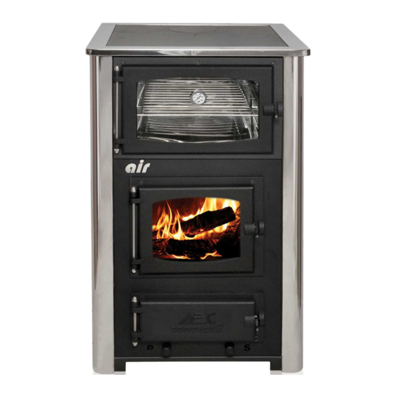
TECHNICAL MANUAL 1. PURPOSE Cookers of air generation are produced in two models: Concept 2 air and Concept 2 mini air, They are intended for cooking and baking food. They use solid fuels: dry wood, coal or briquettes. They give the impression of fireplace, thanks to a fireproof glass on the firebox door. -
Page 5: Technical Specifications
TECHNICAL MANUAL 2. TECHNICAL SPECIFICATIONS Air cookers are made of a certified boiler plate. At higher temperatures we guarantee chemical composition and mechanical properties of the cookers. They are welded with the latest welding methods. (Table 1) Technical specifications for the air cookers Concept 2 Concept 2 Characteristics:... -
Page 6: Appearance And Structure Of The Cookers
15. Cover of cleaning opening 7. Primary “P” airflow (draft) regulator 16. Rear side (back) 8. Secondary “S” airflow (draft) 17. Opening for outdoor air supply regulator 9. Smoke direction regulator (Fig. 1) Cooker Concept 2 air - left www-abcproizvod.co.rs Page... - Page 7 TECHNICAL MANUAL 3.2. Concept 2 mini air 1. Firebox door 9. Oven grate 2. Ashtray door 10. Stovepipe connection, back 3. Oven door 11. Latch for closing the door 4. Oven thermometer 12. Removable handle 5. Flue pipe connector 13. Rear side (back) 6.
-
Page 8: Safety Instructions
Concept 2 Air and Concept 2 mini Air. (Fig. 3a) Concept 2 Air; 1- fireproof layer, and 2- radiotion zone of the cooker (Fig. 3b) Concept 2 mini Air; 1- fireproof layer, and 2- radiation zone of cooker www-abcproizvod.co.rs... -
Page 9: Installation
Any alteration and modification of the stove is forbidden. Only original parts provided by the factory “ABC PROIZVOD” LLC, Užice, can be used. Air cookers must be connected to a chimney that meets all national regulations and standards. - Page 10 TECHNICAL MANUAL Sizing and verification of the chimney (height, cross-section, isolation and positioning of the chimney above the roof top) performs the designer based on the capacity of the cooker, fuels, necessary draft and other. If there is a large draft it can be regulated by installing a flap with positioner on the flue pipe.
-
Page 11: Selection Of Fuel Type
TECHNICAL MANUAL CORRECT INCORRECT (Fig. 6) Connecting the flue pipe (shuttle) to the chimney Positioning of the chimney top above the roof level depends on the slope of the roof and the horizontal distance of the chimney from the roof top. (Fig. -
Page 12: Regulation Of Draft
Concept 2 air cooker is produced in two versions: left-sided or right-sided. On the left-sided cooker, oven is located on the left side of the cooker and the lever for regulating the secondary draft is the left one, indicated with letter “S”... -
Page 13: Use
3. lever for regulating the path of flue gases (Fig. 9) Concept 2 air cooker – left-sided (oven is located on the left side of the cooker) 8. USE Air cookers are designed for space heating, cooking and baking food. -
Page 14: Regulating The Intensity Of Fire
TECHNICAL MANUAL 3) and levers for regulating the draft “P” and “S” (Fig. 9, items 1 and 2) position depending on the desired intensity of the fire. Firing should be started with moderate intensity in order to avoid sudden changes in temperature. Regulating the intensity of the fire When the fire flares up after initial firing: •... -
Page 15: Cleaning And Maintenance
TECHNICAL MANUAL Battens can be reached by lifting the hob of the cooker. First, remove the top batten (1) and then use the wire with a hook at its end, to hook the bottom batten (2) through the hole located at the end of the batten and take it out. - Page 16 The frequency of cleaning depends primarily on the quality of fuel. Perform cleaning at least once per month, as follows: a) Concept 2 air cooker (See Fig. 11): • First, remove the hobs from the cooker and clean their bottom side from deposits of combustion products.
- Page 17 TECHNICAL MANUAL (Fig. 11) 1 – front mask of the opening for cleaning and 2 - opening for cleaning after removing: the mask, the cover and the gasket of the opening for cleaning. b) Concept 2 mini air cooker (See Fig. 12): •...
-
Page 18: Operation Irregularities And Their Elimination
TECHNICAL MANUAL (Fig. 12) Cleaning the flue pipes around the oven 10. OPERATION IRREGULARITIES AND THEIR ELIMINATION Dear users of the air generation of cookers, the proper use and maintenance can guarantee you a long-time reliable partner for comfortable heating. The following table shows the most common operation irregularities and recommendations for their elimination. - Page 19 - Clean the firebox grate If you failed to remove technical defects due to the possible production deficiencies, please contact the factory “ABC PROIZVOD” LLC, Užice, for advice/intervention. 11. WARRANTY YEAR The company “ABC PROIZVOD” LLC, WARRANTY Užice, for air generation of cookers gives...
-
Page 20: Warranty
Installation must be done in accordance with installation instructions included with product and all local and national building and fire codes. ABC Proizvod manufacturer and Sopka Inc importer will not be liable for incidental and consequential damage of any nature. This warranty gives the purchaser specific legal rights which may vary from state to state. -
Page 21: Appendix
EN 13240: 2001/ A2: 2004: EN 13240: 2001/ AC: 2006 and EN 13240: 2001/ A2: 2004/ AC: 2007 In 2007, the company “ABC PROIZVOD” LLC, Užice, has introduced a system of quality management SRPS ISO 9001/ 2008, which is constantly maintained and improved. -
Page 22: Additional Us And Canadian Installation Instruction
Owner’s Manual Tested t t t t o o o o U U U U L L L L 1 1 1 1 4 4 4 4 8 8 8 8 2 2 2 2 , , , , U U U U L L L L C C C C - - - - S S S S 6 6 6 6 2 2 2 2 7 7 7 7 Solid Fuel Room Heater T T T T e e e e s s s s t t t t e e e e d d d d t t t t o o o o : : : : E E E E N N N N 1 1 1 1 2 2 2 2 8 8 8 8 1 1 1 1 5 5 5 5... - Page 23 SAFETY INSTRUCTIONS Read all instructions carefully. 1. The installation of this stove must comply with your local building codes. Please observe the clearance to combustible. Stove must be 12"(30cm) from any combustible material, wall, wood, furniture, paper, etc. 2. Always connect this stove to a chimney and vent outside. This stove requires approved masonry or factory build 6"...
- Page 24 MUST extend under the stove pipe. (Check local building codes and fire protection ordinances.) Floor protector minimum size; „Concept 2 Air“ 56“ x 47“; „Concep 2 mini Air“ 39“ x 47“ 3. The stove must have its own flue. DO NOT CONNECT THIS UNIT TO A CHIMNEY SERVING OTHER APPLIANCES.
- Page 25 Chimney connector systems and clearances Chimney connector shall not pass through attic or roof space, closet or similar concealed space, or a floor, or ceiling. When passage through a wall, or partition of combustible is desired, the installation shall con-form to CAN/CSA-B365, Installation Code for Solid-Fuel-Burning Appliances and Equipment: Page 22...
- Page 26 CLEARANCES: Combustible NON-combustible (Protected Walls) 12"(30cm) 4"(10cm) Back of Stove 12"(30cm) 4"(10cm) Side of Stove Page 23...
- Page 27 Page 24...
- Page 28 MINIMUM CLEARANCES TO COMBUSTIBLE SURFACES Unit to Sidewall - - - - - - - - - - - -12" (30 cm) CAUTION: KEEP FURNISHING AND OTHER Unit to Backwall - - - - - - - - - - - -12" (30 cm) COMBUSTIBLE MATERIALS AWAY FROM THE Unit Corner to wall - - - - - - - - - 12"(30 cm) STOVE.
- Page 29 CAUTION: HOT WHILE IN OPERATION. KEEP CHILDREN, ANIMALS, CLOTH-ING AND FURNITURE AWAY FROM THE STOVE. DO NOT TOUCH HOT STOVE. CONTACT MAY CAUSE SKIN BURNS. TRAIN CHILDREN TO STAY A SAFE DIS-TANCE FROM THE UNIT. CHILDREN SHOULD BE ALL THE TIME CAREFULLY SUPERVISED WHEN THEY ARE IN THE SAME ROOM WITH THE STOVE.
- Page 30 causing the stove or chimney pipe joins to smoke. SOLUTION: Open nearby window, and use small strips of newspaper or tinder loosely placed in the firebox that will pro-vide quick and hot heat up the chimney, thereby reversing draft. SINGLE WALL PIPE-MINIMUM CLEARANCES FOR USA/CANADA Some example of clearance reduction;...
- Page 31 RULES FOR INSTALLATION The stove may not be positioned in the immediate vicinity of the wooden elements, parts made of plastic, textile and other flammable materials because during the operation (during the fuel combustion) it has high work temperature which is distributed on the outside of the stove.
- Page 32 The chimney guarantees the conveyance of the fumes outwards even when there are strong horizontal winds and stops them from being blown back down the chimney. Bad maintenance of the chimney stops the smoke passage due to breakage or separation of cement mortar, brick or other material used for chimney construction, as well as due to product deposits combustion and intrusion of foreign objects.
- Page 33 The position and size of connections Concept 2 Air (Fig. 1) Concept 2 Mini Air (Fig. 2) Page 30...
- Page 34 Dear buyers, if you are not satisfied with working order of the stove Concept 2 air, we beg you to check the following before contacting us in order to request on-site service: 1.
- Page 35 WHAT TO DO IF YOU DO NOT INTEND TO USE THE STOVE FOR AN EXTENDED PERIOD First, clean the hearth, the smoke pipes and the flue, trying to eliminate completely the ash and other residuals. In case you disconnect the appliance from the chimney, close its opening in order to allow operation of other possible appliances connected to the same flue.
- Page 36 Glass getting dirty • Wet wood: use dry wood (with max 20 % moisture) • Wrong fuel (see allowed materials) • Too much fuel in the hearth or the wood touches the glass • Insufficient air flow (see connecting the chimney) •...
- Page 37 CONCEPT 2 MINI AIR Page 34...
- Page 38 Parts Concept 2 Mini Air Page 35...
- Page 39 Parts Concept 2 Air Page 36...
- Page 40 84" (213 cm) Floor / Ember protector minimum size: Concept 2 Air 56" x 47" (142cm x 120cm); Concept 2 mini Air 39" x 47"(98cm x 120cm). Clearances can be reduced with shielding acceptable to local authorities. Reduced installation must comply with NFPA 211 or CAN/CSA-B365.
Need help?
Do you have a question about the Concept 2 air and is the answer not in the manual?
Questions and answers