
Related Manuals for Surna SCMDH-300


Summary of Contents for Surna SCMDH-300
- Page 1 303.993.5271 Surna Dehumidifier Operating & Maintenance Manual Models: SCMDH-300 Revised: August 2016...
-
Page 3: Table Of Contents
Table of Contents Warranty Information Parts List Intended Application Safety Guide Technical Description Specifications Installation Instructions Normal Operation Routine Maintenance Troubleshooting Wiring Diagram... -
Page 4: Warranty Information
Warranty Information Equipment manufactured by Surna (“Company”), Warranty shall be limited to the purchase price of the the warranty shall exist for a period of twelve (12) Equipment shown to be defective. months from initial start-up or 18 months from date of... -
Page 5: Parts List
Dehumidifier Parts Intended Application Below is a list of all parts provided with each The Surna Dehumidifier is intended to operate in Surna Dehumidifier. temperatures between 74 - 86 degrees F and a relative humidity of 40% or higher. 1. Surna Dehumidifier 2. Surna Dehumidifier Product Manual To ensure effective humidity control, the location 3. -
Page 6: Safety Guide
DANGER: Risk of death/serious injury if danger isn’t avoided. document contains all information required to install and operate the Surna dehumidifying device. Failure to follow the directions provided could cause damage Safety Symbols Used to the dehumidifier equipment and/or accessory equipment, damage to building facilities, and/or serious injury or death to the operator. - Page 7 The power supply cord contains a ground fault circuit interrupter (GFCI) that senses damage to the power cord. To test your power supply cord do the following: 1. Plug in the Surna Dehumidifier. Only use parts provided with, or specified for use in this 2. The plug head has two buttons document for use with the dehumidifier equipment, TEST/RESET.
-
Page 8: Technical Description
Technical Description Figure 1 - Dehumidifier Refrigeration System Overview The Surna Dehumidifier uses a refrigeration system cycle to remove heat and moisture from the environment. Low-pressure refrigerant gas is compressed in the compressor and flows to the condenser coil. The refrigerant is condensed to a liquid and gives off heat to the outside air. The refrigerant pressure and temperature are reduced by passing through a series of capillary tubes which act like an expansion valve. Refrigerant then flows to the evaporator coil. The evaporator coil is where heat is transferred from the incoming air to the liquid... -
Page 9: Specifications
Specifications Model Number • SCMDH-300 Dimensions • Length: 25.4” • Width: 26” • Height: 17.3” • Weight: 132 lbs Operating Characteristics • Nominal Capacity: 25,000 BTU/hr • Nominal Dehumidification: 300 pints/day • Fan Motor: 150W • Fan Airflow: 560 SCFM Electrical Data • Voltage/Phase: 208/230 Single Phase •... -
Page 10: Installation Instructions
The disconnect device shall be accessible to users, have a clearly marked On/ Off position and must disconnect all current carrying The Surna Dehumidifier requires a minimum of 12” vertical clearance above the unit when hanging. conductors simultaneously. - Page 11 Figure 2 - Installation Diagram Figure 2 shows proper mounting of the Surna Dehumidifier, with required clearances and recommended condensate trap.
- Page 12 B: Min. 24” (recommended 72”) of clearance from any wall or structure in front of intake or any wall or structure in front of intake or discharge discharge 1: Surna Dehumidifier i f i 2: Do not block intake or discharge Do not block intake or discharge...
- Page 13 B: Min. 24” (recommended 72”) of clearance between two units with adjacent intakes with adjacent intakes 1: Surna Dehumidifier 2: Surna Air Handler i f i 3: No conditioned air discharge or circulating fans within minimum 3’ (recommended 72”) from intake or discharge of unit...
- Page 14 A: Min. 12” of clearance above and below unit Min 12 inches of clearance above and below 1: Surna Dehumidifier 2: Surna Air Handler i f i 3: No conditioned air discharge or circulating fans within minimum 3’ (recommended 72”) from intake or discharge of unit...
- Page 15 4: No conditioned air discharge or circulating fans within minimum 3’ (recommended 72”) from intake or discharge of unit Min 24 inches (recommended 72 inches) Figure 6 - Bird’s Eye View of Clearances Figure 6 provides a Bird’s Eye View of proper installation of the Surna Dehumidifier, with recommended clearances.
-
Page 16: Normal Operation
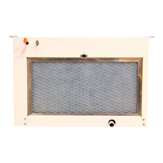
Normal Operation To start normal operation, flip the switch on the front of the unit to the “ON” position and set the provided humidity controller to the desired setting for the space. Mounting Brackets Dehumidistat Switch Filter Set Screw Connector ON/OFF Toggle Switch Condensate Drain Power Cord Figure 7 - Installation Connections... -
Page 17: Routine Maintenance
(optional) coils, as it may be corrosive. When done cleaning, it should be possible to see light showing through The Surna Dehumidifier comes equipped with an the filter. electrostatic filter. If properly maintained, electrostatic b. If it is not possible to clean the filter filters will provide long lasting filtration. It is... -
Page 18: Troubleshooting
Troubleshooting Technician Prior to calling Surna technical support, follow these troubleshooting steps. While steps 1-6 may be handled 7. Check that air is being pulled through the by anyone with basic knowledge of the dehumidifier evaporator coil and pushed out the condenser coil. set up, steps 7-12 should be handled by a trained 8. -
Page 19: Wiring Diagram
RED (24 VAC) WHITE (COM) GREEN TOGGLE SWITCH BLUE YELLOW FAN MOTOR CONTACTOR WHITE LINE NEUTRAL WHITE BLUE Supplied 230 VAC Plug/Power Cord COMPRESSOR RANCO TEMP CONTROL DELAY RELAY HUMIDITY CONTROL BLUE BLUE SCHEMATIC DIAGRAM: SCMDH-300 Figure 8 - Wiring Diagram... - Page 20 303.993.5271 | info@surna.com | surna.com 1780 55th Street Suite A, Boulder, CO 80301...
Need help?
Do you have a question about the SCMDH-300 and is the answer not in the manual?
Questions and answers