
Related Manuals for Fisher FSPI-180AE1


Summary of Contents for Fisher FSPI-180AE1
-
Page 1: Service Manual
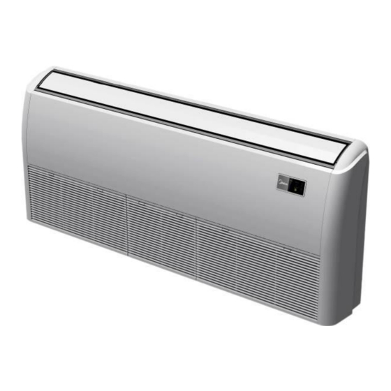
SERVICE MANUAL Spilt Air Conditioner unit Ceiling & Floor Type FSPI-180AE1 / FSOIF-180AE1 FSPI-240AE1 / FSOIF-240AE1 FI_SM_FSPI-180-240-AE1_20131010... -
Page 2: Table Of Contents
Part 1 Indoor units 1. Features ..............3 2. Dimensions ..............4 3. Service Space............. 5 4. Wiring Diagrams ............6 5. Electric Characteristics ..........7 6. Sound Levels ............. 7 7. Accessories ..............8 8. The Specification of Power ........8 9. -
Page 3: Features
Features 1. Features 1.1. New design, more modern and elegant appearance. 1.2. 1.2. Convenient installation --The ceiling type can be easily installed into a corner of the ceiling even if the ceiling is very narrow --It is especially useful when installation of an air conditioner in the center of the ceiling is impossible due to a structure such as one lighting. -
Page 4: Dimensions
Dimensions 2. Dimensions Capacity (Btu/h) 18K, 24K 1068... -
Page 5: Service Space
Service Space 3. Service Space... -
Page 6: Wiring Diagrams
Wiring Diagrams 4. Wiring Diagrams 18k , 24k indoor... -
Page 7: Electric Characteristics
Electric Characteristics 5. Electric Characteristics Indoor Units Power Supply Model Voltage Min. Max. 220-240 220-240 Note: MFA: Max. Fuse Amps. (A) 6. Sound Levels Microphone 1.5m Air outlet side Microphone Ceiling Floor Noise level dB(A) Sound Power Model dB (A) -
Page 8: Accessories
Accessories 7. Accessories 1. Remote controller Remote controller & Its 2. Remote controller holder holder 3. Mounting screw (ST2.9×10-C-H) 4. Alkaline dry batteries (AM4) 5. Owner's manual Others 6. Installation manual 7. Remote controller manual 8. The Specification of Power Model 18k 24k Phase... -
Page 9: Field Wiring
Outdoor Units 9. Field Wiring Outdoor Units... - Page 10 Outdoor Units Part 2 Outdoor Units 1. Dimensions ....................11 2. Service Space ....................12 3. Piping Diagrams .................... 13 4. Wiring Diagrams ................... 14 5. Electric Characteristics ................15 6. Operation Limits ................... 16 7. Sound Levels ....................17 Outdoor Units...
-
Page 11: Dimensions
Dimensions 1. Dimensions Unit:mm Model Outdoor Units... -
Page 12: Service Space
Service Space 2. Service Space (Wall or obstacle) More than 30cm Air inlet More than 60cm More than 30cm Maintain channel Air inlet More than 60cm Air outlet More than 200cm Outdoor Units... -
Page 13: Piping Diagrams
Piping Diagrams 3. Piping Diagrams 18k, 24k INDOOR OUTDOOR Electronic CAPILIARY TUBE expansion valve LIQUID SIDE 2-WAY VALVE T3 Condenser temp. sensor HEAT EXCHANGE HEAT (EVAPORATOR) T4 Ambient T1 Room temp. EXCHANGE temp. sensor sensor (CONDENSER) T2 Evaporator temp. sensor GAS SIDE 4-WAY VALVE Accumulator... -
Page 14: Wiring Diagrams
Wiring Diagrams 4. Wiring Diagrams 18k,24k Outdoor Units... -
Page 15: Electric Characteristics
Electric Characteristics 5. Electric Characteristics Outdoor Unit Model Voltage Min. Max. 220-240V 198V 254V 220-240V 198V 254V Outdoor Units... -
Page 16: Operation Limits
Operation Limits 6. Operation Limits Temperature Cooling operation Heating operation Mode ≥17℃ Room temperature ≤30℃ Outdoor temperature -15℃~50℃ -15℃~24℃ CAUTION: 1. If the air conditioner is used beyond the above conditions, certain safety protection features may come into operation and cause the unit to operate abnormally. 2. -
Page 17: Sound Levels
Sound Levels 7. Sound Levels Outdoor Unit Microphone 1.0m Note: H= 0.5 × height of outdoor unit Model Sound Power dB(A) Outdoor Units... - Page 18 Installation Part 3 Installation 1. Installation Procedure ............19 2. Location selection ............20 3. Indoor unit installation ............. 21 4. Outdoor unit installation (Side Discharge Unit) .... 24 5. Refrigerant pipe installation ..........25 6. Drainage pipe installation..........26 7.
-
Page 19: Installation Procedure
Installation Procedure 1. Installation Procedure Indoor unit installation Outdoor unit installation location selection location selection Indoor unit installation Outdoor unit installation Refrigerant pipe Refrigerant pipe installation and insulation installation and insulation Drainage pipe installation Drainage pipe installation and insulation and insulation Vacuum drying and leakage checking Additional refrigerant charge Insulation the joint part of refrigerant pipe... -
Page 20: Location Selection
Location selection 2. Location selection 2.1 Indoor unit location selection The place shall easily support the indoor unit’s weight. The place can ensure the indoor unit installation and inspection. The place can ensure the indoor unit horizontally installed. ... -
Page 21: Indoor Unit Installation
Ceiling & floor indoor unit installation 3. Ceiling & floor indoor unit installation Service space for indoor unit Bolt pitch ① Ceiling installation Capacity (Btu/h) 18K, 24K ② Wall-mounted installation Installation... - Page 22 Ceiling & floor indoor unit installation Install the pendant bolt ① Ceiling installation Select the position of installation hooks according to the hook holes positions showed in upper picture. Drill four holes of Ø12mm, 45~50mm deep at the selected positions on the ceiling. Then embed the expansible hooks (fittings).
- Page 23 Ceiling & floor indoor unit installation Put the side panels and grilles back. ② Wall-mounted installation Hang the indoor unit by insert the tapping screws into the hanging arms on the main unit. (The bottom of body can touch with floor or suspended, but the body must install vertically.) Installation...
-
Page 24: Outdoor Unit Installation (Side Discharge Unit)
Outdoor unit installation (Side Discharge Unit) 4. Outdoor unit installation (Side Discharge Unit) 4.1 Service space for outdoor unit (Wall or obstacle) Air inlet More than 30cm More than 60cm More than 30cm Maintain channel Air inlet More than 60cm Air outlet More than 200cm 4.2 Bolt pitch... -
Page 25: Refrigerant Pipe Installation
Refrigerant pipe installation 5. Refrigerant pipe installation 5.1 Maximum pipe length and height drop Considering the allowable pipe length and height drop to decide the installation position. Make sure the distance and height drop between indoor and outdoor unit not exceeded the date in the following table. Model Max. -
Page 26: Drainage Pipe Installation
Drainage pipe installation exogenous impurity come into the pipe. 5.2.7 Drill holes if the pipes need to pass the wall. 5.2.8 According to the field condition to bend the pipes so that it can pass the wall smoothly. 5.2.9 Bind and wrap the wire together with the insulated pipe if necessary. 5.2.10 Set the wall conduit 5.2.11 Set the supporter for the pipe. - Page 27 Drainage pipe installation According to the above table to calculate the total water flowrate for the confluence pipe selection. For horizontal drainage pipe (The following table is for reference) Allowable maximum water flowrate (l/h) Reference value of inner PVC pipe Remark diameter of pipe (mm) Slope 1/50...
- Page 28 Drainage pipe installation 6.2.3 Individual design of drainage pipe system The drainage pipe of air conditioner shall be installed separately with other sewage pipe, rainwater pipe and drainage pipe in building. The drainage pipe of the indoor unit with water pump should be apart from the one without water pump. 6.2.4 Supporter gap of drainage pipe ...
- Page 29 Drainage pipe installation Indoor unit More than 50mm Plug More than 25mm Water storage pipe 6.2.7 Lifting pipe setting of indoor unit with water pump The length of lifting pipe should not exceed the pump head of indoor unit water pump. Pump head of big four way cassette: 750mm Pump head of compact four way cassette: 500mm ...
- Page 30 Drainage pipe installation 6.3 Drainage test 6.3.1 Water leakage test After finishing the construction of drainage pipe system, fill the pipe with water and keep it for 24 hours to check whether there is leakage at joint section. 6.3.2 Water discharge test Natural drainage mode(the indoor unit with outdoor drainage pump) Infuse above 600ml water through water test hole slowly into the water collector, observe whether the water can discharge through the transparent hard pipe at drainage outlet.
-
Page 31: Vacuum Drying And Leakage Checking
Vacuum Drying and Leakage Checking 7. Vacuum Drying and Leakage Checking 7.1 Purpose of vacuum drying Eliminating moisture in system to prevent the phenomena of ice-blockage and copper oxidation. Ice-blockage shall cause abnormal operation of system, while copper oxide shall damage compressor. ... -
Page 32: Additional Refrigerant Charge
Additional refrigerant charge 8. Additional refrigerant charge After the vacuum drying process is carried out, the additional refrigerant charge process need to be performed. The outdoor unit is factory charged with refrigerant. The additional refrigerant charge volume is decided by the diameter and length of the liquid pipe between indoor and outdoor unit. -
Page 33: Engineering Of Insulation
Engineering of insulation 9. Engineering of insulation 9.1 Insulation of refrigerant pipe 9.1.1 Operational procedure of refrigerant pipe insulation Cut the suitable pipe → insulation (except joint section) → flare the pipe → piping layout and connection→ vacuum drying → insulate the joint parts 9.1.2 Purpose of refrigerant pipe insulation ... -
Page 34: Engineering Of Electrical Wiring
Engineering of electrical wiring 9.2.3 Insulation material selection for drainage pipe The insulation material should be flame retardant material, the flame retardancy of the material should be selected according to the local law. Thickness of insulation layer is usually above 10mm. ... -
Page 35: Test Operation
Test operation 11. Test operation 11.1 The test operation must be carried out after the entire installation has been completed. 11.2 Please confirm the following points before the test operation. The indoor unit and outdoor unit are installed properly. ... - Page 36 Electrical Control System Part 4 Electrical Control System 1. Electrical Control Function ........37 2. Troubleshooting ............46 Electrical Control System...
- Page 37 Electrical Control Function 1. Electrical Control Function 1.1 Definition T1: Indoor room temperature T2: Coil temperature of indoor heat exchanger middle. T2B: Coil temperature of indoor heat exchanger outlet. T3: Coil temperature of condenser T4: Outdoor ambient temperature T5: Compressor discharge temperature 1.2 Main Protection 1.2.1 Time delay at restart for compressor.
- Page 38 Electrical Control Function 1.3 Operation Modes and Functions 1.3.1 Fan mode (1) Outdoor fan and compressor stop. (2) Temperature setting function is disabled, and no setting temperature is displayed. (3) Indoor fan can be set to high/(med)/low/auto; (4) The louver operates same as in cooling mode. High Medium Ts=24...
- Page 39 Electrical Control Function 1.3.2.3 Indoor fan running rules High Medium 1.3.2.4 Evaporator low temperature T2 protection. When T2<2 and lasts for 3 minutes, the indoor has no capacity demand and resume till T2≥7 . 1.3.2.5 Condenser high temperature T3 protection When T3≥65℃...
- Page 40 Electrical Control Function 1.3.3.3 Indoor fan running rules: When the compressor is on, the indoor fan can be set to high/(med)/low/auto. And the anti-cold wind function has the priority. Auto fan action: T1-Ts- ¦ ¤ Medium High Anti-cold Wind Function: Setting fan speed Breeze Fan off...
- Page 41 Electrical Control Function 4. T3≤TempEnterDefrost_ADD ℃ Cleared conditions (Meet any one of the following conditions) 1. Compressor is off. 2. T3>TempEnterDefrost_ADD ℃ Time2 Time conditions(Meet the following conditions) 1.Running in heating mode 2. T4<3℃ 3. Compressor is on 4. T3≤TempEnterDefrost_ADD ℃ Cleared conditions (Meet any one of the following conditions) 1.
- Page 42 Electrical Control Function 1.3.3.5 High evaporator coil temp.T2 protection: T2>60℃, the compressor will stop and restart when T2<54℃. 1.3.4 Auto-mode This mode can be chosen with remote controller and the setting temperature can be changed between 17~30℃. In auto mode, the machine will choose cooling, heating or fan-only mode according to ΔT (ΔT =T1-Ts). ΔT=T1-Ts Running mode Cooling...
- Page 43 Electrical Control Function When cooling, the setting temperature rises 1℃ (be lower than 30℃) every one hour, 2 hours later the setting temperature stops rising and the indoor fan is fixed at low speed. When heating, the setting temperature decreases 1℃ (be higher than 17℃) every one hour, 2 hours later the setting temperature stops rising and indoor fan is fixed at low speed.
- Page 44 Electrical Control Function turning-off follow-me signal from wired remote controller, the unit will quit follow-me function at once. The follow-me function controlled by wired remote controller prevails that by wireless remote controller. 1.3.11 Point Check Function There is a check switch in outdoor PCB. Press the switch SW1 to check the states of unit when the unit is running.
- Page 45 Electrical Control Function Frequency limit Bit0 caused by voltage DC fan motor speed The display value is between 30~120 degree. If the temp. is lower than 30 degree, the digital display tube will show “30”.If the temp. is higher than 99 degree, the digital display tube will IGBT radiator temp.
-
Page 46: Troubleshooting
Troubleshooting 2. Troubleshooting 2.1 Display board Display board of Ceiling-floor indoor unit 2.2 Indoor unit malfunction Defrosting Alarm Timer Display(digital Malfunction Running lamp lamp lamp lamp tube) Communication malfunction between indoor ☆ and outdoor units. Open or short circuit of T1 temperature ☆... - Page 47 Troubleshooting 2.3 Outdoor unit malfunction Display Malfunction or Protection Outdoor EEPROM malfunction Indoor / outdoor units communication error Communication malfunction between IPM board and outdoor main board Open or short circuit of T3 or T4 temperature sensor Voltage protection of compressor Top temperature protection of compressor Current protection of compressor Discharge temperature protection of compressor...
- Page 48 Troubleshooting 2.4 Solving steps for typical malfunction 2.4.1 For the indoor unit 2.4.1.1 Open or short circuit of temperature sensor Electrical Control System...
- Page 49 Troubleshooting 2.4.1.2. Outdoor unit malfunction Electrical Control System...
- Page 50 Troubleshooting 2.4.1.3. Indoor EEPROM malfunction 2.4.1.4. Full-water malfunction Electrical Control System...
- Page 51 Troubleshooting 2.4.1.5. Indoor fan Speed has been out of control. (Only for the units used AC motor) Shut off the power supply and turn it on 5 seconds The unit operates normally. later.Is it still displaying the error code? S h u t o f f t h e p o w e r Disassembly the supply , rotate the cross connection between...
- Page 52 Troubleshooting 2.4.2 For the outdoor unit 2.4.2.1. E0 malfunction E0 display Outdoor EEPROM malfunction If the EEPROM chip is welded on PCB, replace the PCB directly. Otherwise, Insert the EEPROM well check whether the EEPROM chip plugged in PCB well? Replace the outdoor main board Electrical Control System...
- Page 53 Troubleshooting 2.4.2.2. E2 malfunction E2 display Indoor / outdoor units communication error Power off, then turn on the unit 5 seconds later(reconnect the power wire).Is the error still displaying after several minutes? Check whether there’s any interference. Remove interference. Such as too many lamps, power Increase the capacity of anti- transformers? Or the signal wire interference...
- Page 54 Troubleshooting 2.4.2.3. E3 malfunction Electrical Control System...
- Page 55 Troubleshooting 2.4.2.4. E4 malfunction Electrical Control System...
- Page 56 Troubleshooting 2.4.2.5. E5 malfunction (For single phase units) E5 display Voltage protection Check the voltage of outdoor unit power supply, whether the voltage Check the power supply between L(1) and N is about 220~240VAC Replace the power board, then check whether the system can run normally Check whether the voltage of IPM board P and N is...
- Page 57 Troubleshooting 2.4.2.6. P0 malfunction Electrical Control System...
- Page 58 Troubleshooting 2.4.2.7. P3 malfunction Electrical Control System...
- Page 59 Troubleshooting 2.4.2.8. P4 malfunction When compressor discharge temperature is higher than 115°C, the unit will stop, and unit runs again when compressor discharge temperature is lower than 90°C. P4 display Temperature protection of compressor discharge Check whether the Check whether the compressor discharge temp.
- Page 60 Troubleshooting 2.4.2.9. P5 malfunction When condenser high temp. is more than 65°C, the unit will stop, and unit runs again when outdoor pipe temp. less than 52°C. Electrical Control System...
- Page 61 Troubleshooting 2.4.2.10. P6 malfunction (For single phase units) At first test the resistance between every two ports of U, V, W of IPM and P, N. If any result of them is 0 or close to 0, the IPM is defective. Otherwise, please follow the procedure below: Electrical Control System...
- Page 62 Troubleshooting 2.4.2.11. P7 malfunction P7 display High temperature protection of evaporator Whether the Whether compressor connection is Reconnect and retest operates? good? Check the Check whether the heat resistance value of exchanger is dirty, the air- the sensor via outlet is blocked and the Replace the temperature sensor Appendix 1,Is it indoor fan is running...
- Page 63 Troubleshooting Appendix 1 Temperature Sensor Resistance Value Table (℃--K) ℃ ℃ ℃ ℃ K Ohm K Ohm K Ohm K Ohm 12.6431 2.35774 0.62973 115.266 108.146 12.0561 2.27249 0.61148 101.517 11.5000 2.19073 0.59386 96.3423 10.9731 2.11241 0.57683 89.5865 10.4736 2.03732 0.56038 84.2190 10.000...
- Page 64 Appendix 2 Unit: ℃---K Discharge temp. sensor table 542.7 68.66 13.59 3.702 511.9 65.62 13.11 3.595 62.73 12.65 3.492 455.9 59.98 12.21 3.392 430.5 57.37 11.79 3.296 406.7 54.89 11.38 3.203 384.3 52.53 10.99 3.113 363.3 50.28 10.61 3.025 343.6 48.14 10.25 2.941...
Need help?
Do you have a question about the FSPI-180AE1 and is the answer not in the manual?
Questions and answers