
Related Manuals for Strobl Strocomp 433

Summary of Contents for Strobl Strocomp 433
-
Page 1: Operating Instructions
Operating Instructions for operating and maintenance personnel Always keep with the machine Compressor Strocomp 433, 656, 864, 865 Art. no. 111593008 / 011 / 024 / 012 Machine no. Rev. 00-0208 365251026... -
Page 2: Table Of Contents
Contents Guide to the Operating Instructions Foreword ..........1 —... - Page 3 ..........3 — Strocomp 433 and 656 ......
- Page 4 Contents Transport, Set-up and Connection Unpacking the machine ....... 4 — Transporting the machine .
- Page 5 Contents Operation Requirements ........6 —...
- Page 6 Contents Decommissioning Temporary decommissioning ......9 — Storing the machine ........9 —...
- Page 7 Contents...
-
Page 8: Guide To The Operating Instructions
Maschinenbau Rudolf GmbH Gewerbegebiet Zingsheim Süd 7 53947 Nettersheim Germany Phone: +49 (0) 2486 80246 0 Fax: +49 (0) 2486 80246 46 Mail: info@strobl-beschichtungstechnik.de Web: www.strobl-beschichtungstechnik.de or the branch or services agent responsible for you. 1 — 1 01_0003_0802GB... -
Page 9: Foreword
About these Operating Instructions 1.1 Foreword These Operating Instructions are intended to familiarise the user with the machine and to assist him in using the machine properly in va- rious possible applications. The Operating Instructions contain important information on how to operate the machine safely, properly and economically. - Page 10 About these Operating Instructions The Branch or Agent serving you, or the Aichtal Works, will be happy to give you more information, should you have any questions follo- wing your study of the Operating Instructions. You will make it much easier for us to answer any questions if you can give us the details of the machine model and the machine num- ber.
-
Page 11: Icons And Symbols
About these Operating Instructions 1.2 Icons and symbols The following icons and symbols are used in the Operating Instruc- tions: " Action symbol Text following this symbol describes tasks which you are required to work through, generally in the sequence shown from top to bottom. ⇒... - Page 12 About these Operating Instructions Danger Particular specifications or instructions and prohibitions with regard to the prevention of personal injury or significant damage are intro- duced with the pictogram illustrated, the word “Danger” written in bold and a line. The associated text is written in italics and is closed off with a line.
-
Page 14: Safety Regulations
Safety Regulations 2 Safety Regulations This chapter summarises the most important safety regulations. This Chapter must be read and understood by all persons who handle the machine. The various regulations are also repeated once more at the appropriate points in the Operating Instructions. Notes Special safety regulations may be necessary for some tasks. -
Page 15: Principle
Safety Regulations 2.1 Principle Use only machines in a technically perfect condition, as designated and being conscious of safety and the dangers, taking account of the Operating Instructions. Any faults, especially those affecting the safety of the machine, must, therefore, be rectified immediately. Make sure that - - no safety equipment is removed, rendered inoperable or modified, - - safety equipment removed for the purposes of maintenance work... -
Page 16: Designated Use
Safety Regulations 2.2 Designated use The machine has been built in accordance with the state of the art technology and recognised safety rules. Nevertheless, its use may constitute a risk to life and limb of the operator or of third parties, or cause damage to the machine and to other property. - Page 17 Safety Regulations All items of the machine’s protective panelling must be fitted or connected up during operation. The machine must be operated only with the safety equipment fitted. Specified maintenance work should be carried out at regular intervals. Any work on the electrical system of the machine must be carried out by trained and qualified electricians only.
-
Page 18: Use Contrary To The Designated Use
Safety Regulations Use of the machine other than described in the section ”Designated 2.3 Use contrary to the use”, or which goes beyond such use, is considered contrary to the designated use designated use. Maschinenbau Rudolf GmbH accepts no liability for damage resulting from such use. -
Page 19: Liability
Safety Regulations 2.4 Liability The operator is obliged to act in accordance with the Operating In- structions. The safety and accident prevention regulations from the following institutions must be observed: - - Industrial Employers’ Liability Insurance Association, - - the responsible corporate liability insurance company. - - the legal authorities in your country. -
Page 20: Personnel Selection And Qualifications
Safety Regulations 2.5 Personnel selection The machine may only be operated or serviced independently by persons who and qualifications - - have reached the minimum legal age; - - are physically capable (rested and not under the influence of alco- hol, drugs or medication);... -
Page 21: Safety Equipment
Safety Regulations 2.6 Safety equipment Never remove or modify safety devices on the machine. Any safety devices removed for set-up, maintenance or repair purpo- ses must be refitted and checked immediately upon completion of the maintenance and repair work. Safety devices must only be repaired, adjusted or replaced by tech- nically qualified experts. -
Page 22: Protective Equipment
Safety Regulations 2.7 Protective equipment The following protective equipment is compulsory throughout the machine working area to limit the risk of injury to personnel. - - Protective helmet - - Protective goggles - - Ear defenders, if the spray gun generates sufficient noise 2 —... -
Page 23: Risk Of Injury - - Residual Risk
Safety Regulations Risk of injury - - The machine has been built in accordance with the state of the art residual risk technology and recognised safety rules. Nevertheless, its use may constitute a risk to life and limb of the operator or of third parties, or cause damage to the machine and to other property. -
Page 24: Risk Of Crushing And Knocking
Safety Regulations 2.9 Risk of crushing and During the following operating modes at the machine: - - Set-up knocking - - Starting up - - Operation - - Cleaning, Troubleshooting, Maintenance - - Decommissioning there is a risk of injury through crushing or knocking. Transporting the The machine does not have any attachment points and should there- machine... -
Page 25: Electrical Contact
Safety Regulations 2.10 Electrical contact The control cabinet, electrical wiring and drive motor pose a risk of fatal injury from electrical contact during the following: - - Starting up - - Operation - - Cleaning, Troubleshooting, Maintenance - - Decommissioning. All electrical assemblies are protected as standard, as per IEC 60204 Part 1 or DIN 40050 IEC 144 in accordance with protection category IP 44. -
Page 26: Risk Of Burns And Scalding
Safety Regulations 2.11 Risk of burns and The engine and pressure equipment pose a risk of burns during the scalding following: - - Starting up - - Operation - - Cleaning, troubleshooting, maintenance - - Decommissioning 2 — 13 03_0131_0802GB... -
Page 27: Place Of Work
Safety Regulations 2.12 Place of work The place of work is the area in which people must remain in order to carry out the work. Machine operator The place of work of the machine operator during operation is at the operating panel on the machine. -
Page 28: Sound Emissions
Safety Regulations 2.15 Sound emissions Sound emissions are generated during the following operating mo- des at the machine: - - Starting up - - Operation - - Cleaning, troubleshooting, maintenance - - Decommissioning Refer to the technical data for the sound pressure level value in the vicinity of the machine. -
Page 29: Spare Parts
Note Accessories that are not included in the scope of supply delivered with the machine are supplied by STROBL and can be purchased through Parts Sales. Please refer to the delivery note for a list of accessories supplied. -
Page 30: Injuries Through Unauthorised Starting Or Use Of The Machine
Safety Regulations 2.19 Injuries through un- During the following operating modes at the machine: - - Starting up authorised starting - - Operation or use of the machine - - Cleaning, Troubleshooting, Maintenance - - Decommissioning there is a risk due to unauthorised starting or use of the machine. Always secure the machine against unauthorised starting before lea- ving the work area. -
Page 32: General Technical Description
General Technical Description 3 General Technical Description This section describes the components and assemblies on this machine and describes how they function. Please note that possible options are also described. Please see the machine card to find out whether a particular option is fitted. Your machine is a Strocomp compressor from Maschinenbau 3.1 Machine designation Rudolf GmbH. -
Page 33: Machine Versions
General Technical Description 3.2 Machine versions These operating instructions are valid for subsequent versions of the machine. Model Type Material no. Strocomp 111593008 Strocomp 111593024 Strocomp 111596011 Strocomp 111596012 The following data can be found on the accompanying machine card and on the rating plate: - - Machine version (voltage and frequency) - - Machine number... -
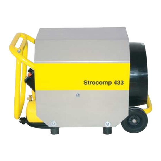
Page 34: Strocomp 433 And 656
General Technical Description 3.4 Summary Below you will find a summary of the most important components; these will then be described on the following pages. Strocomp 433 and 656 View from right Item Designation Control cabinet Air filter Compressor Safety valve (obscured) - Page 35 General Technical Description View from front Item Designation Air filter Oil filler with oil dipstick Compressor Control cabinet Drain valve Pressure tank Oil drain plug ”Working pressure” handwheel ”Tank pressure” gauge Pressure-reducing valve ”Working pressure” gauge Continued next page 3 — 4 02_0460_0802GB...
-
Page 36: Strocomp 864 / 865
General Technical Description Strocomp 864 / 865 View from right Item Designation Control cabinet Compressor Engine Safety valve Axle and wheels Pressure tank Check valve Dump valve External device plug Drain valve 3 — 5 02_0460_0802GB... - Page 37 General Technical Description View from front Item Designation Air filter Oil filler with oil dipstick Compressor Oil drain plug Control cabinet Drain valve Pressure tank ”Working pressure” handwheel Pressure-reducing valve ”Tank pressure” gauge ”Working pressure” gauge 3 — 6 02_0460_0802GB...
-
Page 38: Dimensions
General Technical Description 3.5 Technical data The technical data and characteristics which follow relate to Strocomp compressors. Strocomp 864 / 865 Strocomp 433 Strocomp 656 Dimensions Length: 840 mm 840 mm 900 mm Width: 470 mm 470 mm 550 mm... -
Page 39: Electrical Connection
General Technical Description Strocomp 864 / 865 Strocomp 433 Strocomp 656 Electrical connection Alternating current Alternating current 3-phase Mains voltage: 1 x 230 - - 250 V / 1 x 230 - - 250 V / 3 x 400 V / 50 Hz... -
Page 40: Rating Plate
General Technical Description 3.6 Rating plate The most important machine data is shown on the rating plate. Item Designation Model (machine model) Mach. no. (machine number) Year of manufacture Max. delivery pressure [bar] Voltage [V] Frequency [Hz] Power [kW] 3 — 9 02_0274_0608GB... -
Page 41: Sound Power Level
General Technical Description 3.7 Sound power level In accordance with Directive 2000/14/EC the sound power level emit- ted by the machine is given below. Next to the rating plate on the machine there is the plate shown in the picture below which gives the machine’s sound power level mea- surement. -
Page 42: Safety Equipment
General Technical Description 3.8 Safety equipment The following is a list of installed safety equipment on the machine. Danger Only operate the machine with the safety equipment fitted and fully functional. Personal protective equipment is not included in the scope of supply Personal protective delivered with the machine. -
Page 43: Functional Description
General Technical Description 3.9 Functional descrip- This chapter is intended to help you understand the operational sequences of the machine so that you can limit the field of the tion machine’s applications to suitable areas and avoid errors in operation. Maschinenbau Rudolf machines are easy to assemble and operate. -
Page 44: Pressure-Reducing Valve
General Technical Description Pressure-reducing valve The pressure-reducing valve ensures that the compressed air generated does not exceed the preset working pressure. The working pressure can be adjusted manually in infinite variables within the defined limit values using the handwheel. The air hose is connected to the pressure-reducing valve. Check valve The check valve opens to allow the compressed air into the pressure tank, while at the same time preventing the stored compressed air... -
Page 45: Control Cabinet
General Technical Description 3.10 Control cabinet The machine is controlled and operated via the control cabinet. High voltage Work on the electrical system and equipment of the machine must be carried out by a qualified electrician or by instructed persons under the supervision and guidance of a qualified electrician and in accordance with the electrical engineering rules and regulations. -
Page 46: With Main Switch
General Technical Description A different control cabinet may be fitted to the machine, depending on the model. with main switch Item Designation Function / display Main switch Machine ON Main switch Machine OFF with rotary switch AUTO Item Designation Function / display Rotary switch Machine ON - - OFF Rotary switch position for... -
Page 47: Operating Elements
General Technical Description 3.11 Operating elements Further elements have been installed on the machine for operation and control. Different models available Item Designation ”Working pressure” gauge ”Working pressure” handwheel ”Tank pressure” gauge The working pressure is displayed on the ”working pressure” gauge (1). -
Page 48: Transport, Set-Up And Connection
Transport, Set-up and Connection 4 Transport, Set-up and Connection In this section you will find information concerning safe transport of the machine. Furthermore, work is described in this section, which is also necessary for the installation and connection of the machine. Starting up the machine will not be described until the chapter ”Star- ting up”. - Page 49 Transport, Set-up and Connection 4.2 Transporting the The machine does not have any attachment points and should there- fore loaded onto a suitable transport aid (euro pallet). Use a suitable machine crane with lifting gear or a fork-lift truck to lift the machine. Danger of crushing Lift the machine carefully with a fork-lift truck and move with great care.
-
Page 50: Transport By Hand
Transport, Set-up and Connection 4.3 Transport by hand Transport the machine by hand as follows: " Shut the machine down. Refer also to chapter: ”Decommissioning”. " Unfold the transport bracket. " Lift the machine slightly by the transport bracket and move to the intended set-up site. -
Page 51: Selecting The Set-Up Site
Transport, Set-up and Connection 4.4 Selecting the set-up The set-up site of the machine is usually determined and appropria- tely prepared by the site management. site Notes The responsibility for setting up the machine safely falls on the ope- rator. 4.5 Set-up site Inspect the proposed site carefully and reject the set-up site if you have any doubts in respect of safety. -
Page 52: Setting Up
Transport, Set-up and Connection Setting up The machine must be set up so that it is absolutely stable and secured against rolling. " Align the machine horizontally. Observe the permitted inclination angles. Inclination angles Observe the maximum inclination angles during machine set-up and operation. -
Page 53: Electrical Connection
Transport, Set-up and Connection 4.7 Electrical connection Please also refer to the ”General Technical Description” or the electri- cal circuit diagram for the electrical connection values. Refer also to chapter ”General Technical Description” - - section: ”Technical data and rating plate” for more details. Heavy current Work on the electrical system and equipment of the machine must be carried out by a qualified electrician or by instructed persons un-... -
Page 54: Laying Electrical Supply Cables
Transport, Set-up and Connection Laying electrical supply Supply cables must be laid visibly, taking local conditions into consi- cables deration, and secured against damage. Danger There is a danger of electric shock which may have lethal conse- quences by: – contact with electrical cables; –... -
Page 55: Connecting The Air Hose
Transport, Set-up and Connection 4.8 Connecting the air hose Different models available Item Designation Pressure-reducing valve Air hose Air hose connection Connect the air hose as follows: Caution Only couple hose couplings which have been cleaned and have good condition. Dirty couplings will invariably leak. "... - Page 56 Starting up 5 Starting up In this chapter you will find information on starting up the machine. The work steps for initial operation of the machine are described as well as how to prepare the machine for operation after a long break. There is also a description on how to check the condition of your ma- chine and how to carry out a test run with function checks.
-
Page 57: Checks
Starting up 5.1 Checks Each time the machine is used at a construction site, you should check the condition of your machine and carry out a test run inclu- ding function checks. If you identify any faults during the checks, you must eliminate these (or have these eliminated) immediately. -
Page 58: Operating Materials
Starting up Operating materials Oil levels Danger Oils and other operating fluids can pose a threat to health if they come into contact with the skin, or similar. You must, therefore, always wear personal protective clothing and equipment when you are handling toxic, caustic or other operating materials that are injurious to health and always take note of the manufacturer’s information. -
Page 59: Compressor Oil Level
Starting up Compressor oil level Check the compressor oil level as follows: " Check the compressor oil level. Maintenance chart: Checking the compressor oil level Note Only fill the compressor to the ”Maximum” mark on the oil dipstick. " Top up the compressor oil if necessary. 5 —... -
Page 60: Test Run
Starting up 5.2 Test run Carry out a test run before operating the machine. Switch-on conditions The following conditions must be met before the machine is switched - - The machine should be in a horizontal position. - - The machine must be connected to a suitable power supply. Read the ”Electrical connection”... -
Page 61: With Rotary Switch
Starting up " Switch on the ”Machine ON” main switch (1). ⇒ The power supply in the control cabinet switches on. ⇒ The engine starts. ⇒ The compressor operates in automatic mode. with rotary switch The machine is switched on at the rotary switch. AUTO Item Designation... -
Page 62: Shutting Down Machine After Starting Up
Starting up 5.4 Shutting down ma- After the function check, you can shut down the machine. chine after starting up with main switch The machine is switched off at the main switch. Item Designation ”Machine ON” main switch ”Machine OFF” main switch "... -
Page 63: With Rotary Switch
Starting up with rotary switch The machine is switched off at the rotary switch. AUTO Item Designation ”Machine ON - - OFF” rotary switch Position for switching off machine is ”OFF” Position for automatic mode is ”AUTO” " Switch the rotary switch (1) to position ”OFF” (2). ⇒... -
Page 64: Requirements
Operation 6 Operation In this section you will find information on machine operation. You will learn what operations are required for setting up the machine, operation and for cleaning. 6.1 Requirements Before starting work, you must carefully carry out the working steps for commissioning and installing the machine. -
Page 65: Emergency Shutdown Procedures
Operation 6.2 Emergency shutdown Make sure you are completely familiar with the procedures for shut- ting down the machine in an emergency situation before you start procedures operating the machine! Danger Proceed immediately as described below if an emergency occurs while you are operating the machine. -
Page 66: Setting The Working Pressure
Operation 6.3 Setting the working You must set the working pressure before operating the machine. pressure Refer to the chapter: ”General Technical Description” - - section: ”Technical data” for information on the maximum delivery pressure of the machine. " Attach the other end of the air hose to a suitable pneumatic tool. -
Page 67: Setting Values
The compressed air output depends on the preset working pressure. The following table contains general guide values for setting the working pressure: Strocomp 864 / 865 Working pressure Strocomp 433 Strocomp 656 Small quantity of approx. 1.0 bar approx. 1.0 bar approx. 1.0 bar... -
Page 68: Operating The Machine
Operation 6.4 Operating the You may begin using the machine once the start-up phase is complete. machine Danger The machine may be operated only with a pneumatic tool con- nected! Proceed as follows: " Switch the machine on. Refer also to chapter: ”Starting up”... -
Page 69: Stopping Delivery
Operation Stopping delivery Stop delivery as follows: " Close the air supply to the pneumatic tool. ⇒ The compressor switches off automatically. " Switch off the machine. Refer also to chapter: ”Starting up” - - section: ”Shutting down the machine after starting up”. -
Page 70: Using The Spray Gun
Operation 6.5 Using the spray gun You can perform the following work using a spray gun connected to a Strobot delivery pump: Danger The machine may be operated only with a pneumatic tool connected! Caution Read the information provided by the manufacturer before connecting ”pneumatic tool”... - Page 71 Operation Note Depending on the model, the material flow is switched on and off using the material lever, the spray gun trigger or the remote control. " Close the material lever on the spray gun (if available). " Close the air valve on the spray gun. "...
-
Page 72: Interrupting Operation
Operation The tank pressure of machines without automatic mode must be checked regularly during operation. " Check the tank pressure on the ”tank pressure” gauge. Caution The tank pressure must remain constant and should never fall below 5 bar. Set the working pressure accordingly. Interrupt operation as follows: Interrupting operation "... -
Page 73: Cleaning The Machine
Operation 6.6 Cleaning the machine Clean the machine after finishing work. Clean the machine to ensures that it will function correctly the next time it is used. Environmental protection Observe all applicable local waste disposal regulations when performing cleaning work. Do not allow cleaning additives to enter the sewerage system. - Page 74 Operation Note In the first four operating weeks clean all painted surfaces with cold water with a maximum water pressure of 5 bar only. Do not use any aggressive cleaning additives. The paint takes a full four weeks to harden properly. Water which sprays the machine from all directions does not have any damaging effect.
- Page 76 Faults, Cause and Remedy 7 Faults, Cause and Remedy This section gives you a summary of faults and their possible cau- ses, and also ways in which you may rectify them. Observe the safety regulations when troubleshooting. Heavy current Work on the electrical system and equipment of the machine must be carried out by a qualified electrician or by instructed personnel under the supervision and guidance of a qualified electrician and in accordance with electrical engineering rules and regulations.
-
Page 77: Machine, General
Faults, Cause and Remedy 7.1 Machine, general The following section provides a description of possible causes of faults and their remedies. Danger Make sure the mains power supply is suitable! Otherwise the machine may be damaged. Note Consult the relevant service department at Maschinenbau Rudolf GmbH if you cannot rectify the fault by yourself. - Page 78 Faults, Cause and Remedy Machine does not start when switched on. The ”tank pressure” gauge displays 3 to 10 bar. The compressor makes a humming noise. Cause Remedy The power supply was Switch off the machine to depressurise the pressure line. interrupted during operation.
- Page 79 Faults, Cause and Remedy Pressure has built up while the machine was operating. The compressor has switched off automatically after reaching the cut-out pressure threshold. The machine does not switch on again even though the tank pressure has decreased. Cause Remedy The dump valve is Clean the dump valve.
- Page 80 Faults, Cause and Remedy The motor protection switch has triggered. Cause Remedy The compressor oil level is too Check the compressor oil level and top up if necessary. low. The air filter is dirty or clogged. Clean the air filter. The air intake area on the com- Remove all objects and obstacles from around the air intake area.
- Page 82 Maintenance 8 Maintenance In this chapter you will find information on the maintenance work ne- cessary for the safe and efficient operation of the machine. Following the general maintenance information, you will find the maintenance charts necessary for this machine. A summary of the maintenance charts listed by number is included in the table of con- tents.
-
Page 83: Maintenance Intervals
Maintenance 8.1 Maintenance intervals The following table shows the intervals for the various maintenance tasks. Caution Inspection and maintenance personnel must have authorisation and the necessary technical qualification. They must have completed training relevant to working with the equipment on the machine and be conversant with the content of the operating instructions. - Page 84 Maintenance Action General machine Electrical cabling: visual inspection, have repaired if necessary Air line: visual inspection for suitability, wear and damage, replace if necessary Draining condensate MC 43- -039 water Have a qualified service Service expert check for defects Operational safety check (German Accident Pre- Service vention Regulation)
-
Page 86: General Maintenance Work
Maintenance Chart 40- -030 Page 1 of 1 General maintenance work This maintenance chart describes general maintenance tasks and contains notes that apply to all maintenance work using maintenance charts. Caution Maintenance work must only be carried out by authorised personnel with special knowledge and experience. -
Page 87: Draining Condensate Water
Maintenance Chart 43- -039 Page 1 of 2 D raining condensate water 4 4 4 4 3 3 3 3 - - - - 0 0 0 0 3 3 3 3 9 9 9 9 This maintenance chart describes how to drain condensate water from the drain valve on the pressure tank. - Page 88 Maintenance Chart 43- -039 Page 2 of 2 " Place a suitable container under the drain valve to catch the water. " Open the drain valve. " Allow the condensate water to drain. " Close the drain valve again. " Drain the second pressure tank in the same way.
-
Page 89: Checking The Compressor Oil Level
Maintenance Chart 43- -040 Page 1 of 2 C hecking the compressor oil level 4 4 4 4 3 3 3 3 - - - - 0 0 0 0 4 4 4 4 0 0 0 0 This maintenance chart describes how to check the compressor oil level. - Page 90 Maintenance Chart 43- -040 Page 2 of 2 Check the compressor oil level as follows: Different models available Item Designation Oil filler with oil dipstick Compressor (depending on the model) " Screw the oil filler with oil dipstick into the top of the compressor.
-
Page 91: Changing The Compressor Oil
Maintenance Chart 43- -041 Page 1 of 3 C hanging the compressor oil 4 4 4 4 3 3 3 3 - - - - 0 0 0 0 4 4 4 4 1 1 1 1 This Maintenance chart describes how to change the oil in the compressor. - Page 92 Maintenance Chart 43- -041 Page 2 of 3 Environmental protection Carefully collect escaping operating fluids and avoid oil spillage. Dispose of all components in accordance with current applicable regulations! Observe the national and regional regulations applicable to your area. Only work with waste disposal companies who are approved by the responsible authorities.
- Page 93 Maintenance Chart 43- -041 Page 3 of 3 " Fill new oil into the oil filler. Refer also to chapter: ”General Technical Description” - - section: ”Technical data” for more information on fluid capacities. Caution The capacities are only approximate values. These may vary according to the design and depend on the quantity of oil remaining.
-
Page 94: Cleaning And Replacing The Air Filter
Maintenance Chart 43- -042 Page 1 of 2 Cleaning and replacing the air filter This Maintenance chart describes how to clean the air filter on the compressor and replace the filter inserts. You will find the maintenance intervals in the maintenance summary at the start of this chapter. - Page 95 Maintenance Chart 43- -042 Page 2 of 2 The following steps describe how to clean and change the air filter: " Remove the air filter. " Remove the filter cover. " Pull the filter insert carefully from the filter housing. Avoid disturbing dust where possible.
-
Page 96: Temporary Decommissioning
Decommissioning 9 Decommissioning This chapter contains information on decommissioning the machine. 9.1 Temporary If the machine is to be shut down temporarily, take the following measures. decommissioning " Terminate delivery. Refer also to chapter: ”Operation” - - section: ”Operating the machine”. "... -
Page 97: Storing The Machine
Decommissioning 9.2 Storing the machine Observe the following when placing the machine in storage: - - Shut down the machine only in current-free condition. - - Clean the machine before storing it. - - Store the machine in a dry, frost-free location. 9.3 Final The final decommissioning and disposal requires complete disassembly of the machine into its individual components. -
Page 98: General Tightening Torques
Appendix 10 Appendix 10.1 General tightening Tightening torques depend on bolt grade, thread friction and bolt head bearing area. The values given in the following tables are for torques guidance. These values should only be used if no other values are specified in the relevant chapters of the Operating Instructions or in spare parts sheets. - Page 99 Appendix The tables below give the maximum tightening torques (maximum torque) in Nm for a friction factor of mtotal = 0.14, with the thread lightly-oiled or lightly-greased. Notes All tightening torques X 1.1 apply for bolts with cement in the thread. Set screws - - metric triangular thread, DIN 13, Part 13 Dimensions Tightening torque...
-
Page 100: Lubricant Recommendation
Appendix We have listed all suitable lubricants in the tables below. 10.2 Lubricant Maschinenbau Rudolf GmbH accepts no liability for the quality of the recommendation lubricants listed or for changes in quality made by the lubricant producer without changing the grade designation. Caution Maschinenbau Rudolf accepts no liability for damage resulting from the use of unauthorised operating materials. - Page 102 Index of Key Words Index of Key Words This chapter contains the main key words with the number of the page on which they are to be found as a header in the left-hand mar- gin. This Index of key words is listed alphabetically by the main con- cepts.
- Page 103 Index of Key Words Accessories, 2 — 16 Dangers Liability, 2 — 6 - Risk of burns, 2 — 13 - Exclusion of liability, 2 — 6 Air filter, 3 — 3, 3 — 4, 3 — 6, 8 — 13 - Risk of scalding, 2 —...
- Page 104 Risk of injury, 2 — 10 Storing the machine, 2 — 16 Rotary switch, 3 — 15, 5 — 6, 5 — 8 Strocomp 433, 3 — 3 Year of manufacture, 3 — 9 Strocomp 656, 3 — 3 Strocomp 864 / 865, 3 — 5 Summary of components, 3 —...
Need help?
Do you have a question about the Strocomp 433 and is the answer not in the manual?
Questions and answers