Table of Contents

Related Manuals for RACOM Ray2

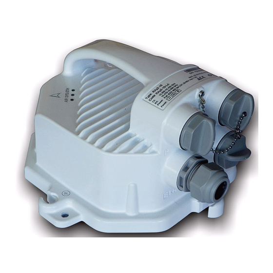
Summary of Contents for RACOM Ray2
- Page 1 User manual RAy2 Microwave Link fw 1.3.x.x 2/18/2015 version 1.8.7 RACOM s.r.o. • Mirova 1283 • 592 31 Nove Mesto na Morave • Czech Republic www.racom.eu Tel.: +420 565 659 511 • Fax: +420 565 659 512 • E-mail: racom@racom.eu...
-
Page 3: Table Of Contents
Table of Contents Important Notice ..........................7 Quick Start Guide ..........................8 List of documentation .......................... 9 1. RAy2 – Microwave Link ......................... 10 2. Implementation Notes ........................12 2.1. Link calculation ........................12 2.1.1. Free space loss calculation ..................12 2.1.2. - Page 4 10.3.4. Nominal frequencies, band 10.15 – 10.65 GHz ..........165 10.4. RAy2-11 A,B parameters ....................169 10.4.1. Upper/Lover Limits ....................169 10.4.2. Radio parameters ....................170 10.4.3. Nominal frequencies, duplex 490 MHz ..............173 10.4.4. Nominal frequencies, duplex 530 MHz ..............179 RAy2 Microwave Link – © RACOM s.r.o.
- Page 5 E. IP address in the PC (Windows 8) ....................224 F. SSH key generation ........................227 G. Https certificate ........................... 229 H. Unit block diagrams ........................230 Index ..............................232 I. Revision History ........................... 235 © RACOM s.r.o. – RAy2 Microwave Link...
-
Page 7: Important Notice
Data may be delayed, corrupted (i.e., have errors), or be totally lost. Significant delays or losses of data are rare when wireless devices such as the RAy2 are used in an appropriate manner within a well‐constructed network. RAy2 should not be used in situations where failure to transmit or receive data could result in damage of any kind to the user or any other party, including but not limited to personal injury, death, or loss of property. -
Page 8: Quick Start Guide
IP address – input 192.168.169.180 and use the mask 255.255.255.0. Click OK twice. • Connect both RAy2 units to a PoE source and connect to a PC via PoE for configuration, see figure Link Configuration below. • Input the address of the connected RAy2 unit into the address field of your internet browser (such as Mozilla Firefox), e.g. -
Page 9: List Of Documentation
List of documentation List of documentation User manuals ■ Microwave Link RAy2 - this document User manual RAy2-10, RAy2-11, RAy2-17, RAy2-24 ■ Microwave Link RAy11, 17, 24 User manual RAy11, RAy17, RAy24 ■ Microwave Link RAy10 User manual RAy10 Datasheets ■... -
Page 10: Ray2 - Microwave Link
RAy2 works with an ethernet interface and can be used in backhaul networks as well as a last-mile terminal.The design of microwave link RAy2 reflects effort on meeting the strictest criteria of ETSI standards, particularly for durability against interference, high receiver sensitivity and high output power to achieve maximum link distance. - Page 11 Electrical safety EN 60950-2006/A1:2010 Note Operation of the RAy2-xx is described in this user manual. Operation of the RAy11, RAy17 and RAy24 is described in User Manual RAy11,17,24 Operation of the RAy10 is described in the RAy10 User Manual http://www.racom.eu/eng/products/m/ray17/index.html http://www.racom.eu/eng/products/m/ray/index.html...
-
Page 12: Implementation Notes
Fresnel zones calculation This chapter explains the individual steps and an example of link design is given at the end. NOTE - For quick reference you can use the calculator on www.racom.eu 2.1.1. Free space loss calculation As the electromagnetic waves travel through open space they are attenuated. This attenuation is de- scribed as Free-space Loss. -
Page 13: Fade Margin
It increases exponentially with rain intensity • It becomes significantly larger as the distance travelled increases (>10 Km) • Horizontal polarization causes greater rain attenuation than vertical polarization • Rain outage increases dramatically with frequency and path length © RACOM s.r.o. – RAy2 Microwave Link... - Page 14 Compute specific attenuation γ (dB/km) for the frequency, polarization, specific rain rate using ITU-R recommendation P.838. Rain attenuation for rain rate γ can be calculated as follows: 0.01 α γ 0.01 0.01 where: RAy2 Microwave Link – © RACOM s.r.o.
- Page 15 Fig. 2.2 shows that rain attenuation is greater for horizontal polarization. In regions with higher precip- itation the difference in attenuation is more marked. The microwave links RAy17 and RAy24 use both polarizations, hence the need to consider the worse of the two, i.e. horizontal polarization. When ACM © RACOM s.r.o. – RAy2 Microwave Link...
-
Page 16: Multipath Fading
From the antenna heights h and h (meters above sea level), calculate the magnitude of the path in- clination │ε │ (mrad) using the following expression: where: link distance (km) antenna heights above sea level (m) RAy2 Microwave Link – © RACOM s.r.o. -
Page 17: Fresnel Zones Calculation
Fresnel zone. From the above formula, calculation of the first Fresnel zone can be simplified where: max radius of first Fresnel zone (m) reducing the radius to 60% get values listed in the following table that define the space particularly sensitive to the presence of obstacles © RACOM s.r.o. – RAy2 Microwave Link... -
Page 18: Example Of Microwave Link Design
Required data rate: >160 Mbps Required availability: 99.99 % RAy parameters: 17 GHz 161 Mbps -> Modulation 16QAM; BW=56 MHz; P (BER 10 )= −79 dBm Tx power +5 dBm (max. Tx power) Antenna gain: RAy2 Microwave Link – © RACOM s.r.o. - Page 19 20 dB at the most. For 99cm antennas, TX power can be up to 20 - 42 = -22 dB, the resultant equation is as follows: − FSL = -22 + 42 + 42 − 129.1 = −67.1 dB © RACOM s.r.o. – RAy2 Microwave Link...
- Page 20 ITU-R P.837-1 and 6 – Characteristics of precipitation for propagation modelling • ITU-R P.838-3 – Specific attenuation model for rain for use in prediction methods • ITU-R P.310, ITU-R P.526, ITU-R P.676, ITU-R P.834, ITU-R P.835 RAy2 Microwave Link – © RACOM s.r.o.
-
Page 21: Product
Fig. 3.1: RAy2 – Microwave link The link is formed by two FOD (Full Outdoor) units. In the case of links operating in the RAy2-17 and RAy2-24 bands, both units have identical hardware. In the case of links operating in licensed bands, one unit (labeled L) is transmitting in the Lower and receiving in the Upper part of the band. -
Page 22: Mounting
3.1. Mounting Fig. 3.2: RAy2 Microwave link – antenna and FOD unit The antenna is attached to the mast using a holder adjustable in two planes. The RAy2 unit is then mounted on the antenna. There are two possible mounting positions – for horizontal and vertical polarization. Installation and adjustment of the holder is described in the Section 6.2, “Antenna mounting”. -
Page 23: Power Supply
For example, the connector CON-RJ45-UBNT-CAT6 and ETH socket on the control panel should have a grounded sheath as should the connection to the RAy2 unit. All bushings and plugs (including the original plugs in the ports) must be fitted with O-rings and carefully tightened. - Page 24 DC grounding - Fig. 3.5, “Grounding options”(c). RAy2 RAy2 RAy2 RAy2 RAy2 Fig. 3.5: Grounding options HW button Fig. 3.6: Power supply connector 1 Fig. 3.7: Power supply connector 2 RAy2 Microwave Link – © RACOM s.r.o.
-
Page 25: Status Leds
500 ms on / 500 ms off Flashing intermittently 50 ms on / 950 ms off Flashing irregularly by passing frames 3.5. Technical parameters Basic technical parameters are stated in chapter Technical parameters. © RACOM s.r.o. – RAy2 Microwave Link... -
Page 26: Dimensions
• RAy2-17 — 2.5 kg • RAy2-24 — 2.5 kg Diameters of supplied antennas RAy2 units are ready for direct mounting to Jirous Class 2 antennas. Individual datasheets are accessible here ○ 10, 11 GHz: • 38 cm, 29.0 dBi •... -
Page 27: Ordering Codes
The proper pair (from the same sub-band) of Lower and Upper units should be selected when ordering the microwave link. This is not valid for RAy2-17 and RAy2-24 units. In such a case the same unit is used for both sides of the link. -
Page 28: Accessories
Power supply PoE 4xEth 90-264 VAC/ 33.6 W/Port 0/+40°C Phihong Power supply holder HOL-POE-PHI-1A DIN rail holder for PoE Phihong HOL-POE-PHI-4A 19" Rack holder for 1xPOE125U-4-AT-N Phihong Surge protection OTH-DL-1GRJ45 Surge protection 1Gb Eth Cat.6 LPZ0B-LPZ1 IP20 -40/+85°C RAy2 Microwave Link – © RACOM s.r.o. - Page 29 DC surge protection OTH-DP-024 Overvoltage protection, DC 24V, LPZ1-LPZ2, IP20, -40/+85°C , Saltek RAy grounding kit KIT-GROUDING-RAY Grounding kit for RAy units RAyTool SET-RAY TOOL Tool set (Knipex, Holex, Wera werk). Heavy duty bag. © RACOM s.r.o. – RAy2 Microwave Link...
-
Page 30: Details
• see the Overview • The bracket for mounting FOD unit on the antenna. Flexible waveguide mounting kit The RAy2 unit can be attached to the antenna by flexible waveguide. • SET-RAY-FX-R100 • SET-RAY-FX-R120 • The bracket for mounting the flexible waveguide on the FOD unit. - Page 31 POE125U-4AT-(x) • FOD unit power supply 4x 33 W, 4x Eth, Phihong • Datasheet Power supply holder • HOL-POE-PHI-1A • 1x Eth PoE power supply, DIN rail mountable http://www.racom.eu/download/hw/ray/free/eng/07_prislusenstvi/PWS-AC-DC-AD-55B.pdf http://www.racom.eu/download/hw/ray/free/eng/07_prislusenstvi/PWR-POE36U-1AT.pdf http://www.racom.eu/download/hw/ray/free/eng/07_prislusenstvi/PWR-POE36D-1AT.pdf http://www.racom.eu/download/hw/ray/free/eng/07_prislusenstvi/PWR-POE125U-4AT-N.pdf © RACOM s.r.o. – RAy2 Microwave Link...
- Page 32 • orig. part no: Harting 09 45 151 1560 Connector RJ45, Cat6, AWG 24-22, HARTING • The connector is assembled without the supplied plastic shell and nut. • Datasheet http://www.racom.eu/download/hw/ray/free/eng/07_prislusenstvi/OTH-DL-1GRJ45.pdf http://www.racom.eu/download/hw/ray/free/eng/07_prislusenstvi/OTH-DL-CAT-6-60V.pdf http://www.racom.eu/download/hw/ray/free/eng/07_prislusenstvi/CAB-CAT5E-FTP-TLD.pdf http://www.racom.cz/download/hw/ray/free/eng/07_prislusenstvi/CON-RJ45-HRT-CAT6.pdf RAy2 Microwave Link – © RACOM s.r.o.
- Page 33 DLCRAC2Fyyy patchcord, 2-fibres, single mode, LC-connector — LC-connector, yyy meters, OFA • CAB-FIB-1F-LC/LC-OFA-5m • orig. part no: LCRAC1Fyyy patchcord, 1-fibre, single mode, LC-connector — LC-connector, yyy meters, OFA http://www.racom.cz/download/hw/ray/free/eng/07_prislusenstvi/SET-RAY2-TLG-EXT35.pdf http://www.racom.cz/download/hw/ray/free/eng/07_prislusenstvi/SFP-RJ45-AVAGO.pdf http://www.racom.eu/download/hw/ray/free/eng/07_prislusenstvi/SFP-DLC-FIN.pdf http://www.racom.eu/download/hw/ray/free/eng/07_prislusenstvi/SFP-DLC-APAC.pdf © RACOM s.r.o. – RAy2 Microwave Link...
- Page 34 RAy grounding set for grounding RAy equipment to the mast. Contains a ZSA16 grounding terminal, grounding tape and a cable with grounding lugs. • Detail see Grounding. • Datasheet http://www.racom.eu/download/hw/ray/free/eng/07_prislusenstvi/CAB-FIB-OFA.pdf https://webservice-new.racom.eu/main/eshop.detail?i=193 http://www.racom.eu/download/hw/ray/free/eng/07_prislusenstvi/OTH-DP-024.pdf http://www.racom.eu/download/hw/ray/free/eng/07_prislusenstvi/ZSA16-en.pdf RAy2 Microwave Link – © RACOM s.r.o.
- Page 35 Extended descriptions See www.racom.eu, Microwave link, Accessories E-shop Accessories easiest to order here: E-shop RACOM Use there a search engine Ctrl+F and RACOM-PART-NUMBER of the searched item. http://www.racom.eu/eng/products/microwave-link.html#accessories https://webservice-new.racom.eu/main/eshop.list?a=1&t=10 © RACOM s.r.o. – RAy2 Microwave Link...
-
Page 36: Step-By-Step Guide
Both units (without antennas) can lie on a desk with flanges running parallel and facing up at an angle; on a non-metal desk they can also face downward. In the case of units RAy2-17 and RAy2-24 turn the unit holders so that they are roughly perpendicular to each other. In the case of units operating in licensed bands (RAy2-10, RAy2-11), turn unit holders so that they are roughly parallel to each other. -
Page 37: Service Access
5.1. Service access The RAy2 link is supplied with a default configuration of access parameters: Unit L has the service IP address 192.168.169.169 and mask 255.255.255.0, Unit U has the service IP address 192.168.169.170 and mask 255.255.255.0, access is allowed over HTTP, HTTPS or SSH, the username is admin and the password is also admin. -
Page 38: Menu Link Settings - General
Station name – station can be assigned with a name, e.g. the place of installation. • Station location – for easier inclusion the network hierarchy, it is possible to enter the station’s loc- ation Fig. 5.2: Configuration Menu Link settings - General RAy2 Microwave Link – © RACOM s.r.o. -
Page 39: Menu Link - Service Access - Services
Management VLAN – Enabling 802.1Q VLAN tag for separation of user and service operations. • Management VLAN id – Defining 802.1Q VLAN tag for service operations. Fig. 5.3: Configuration menu Link settings – Service access – Services © RACOM s.r.o. – RAy2 Microwave Link... -
Page 40: Menu Link - Service Access - Users
TX and RX. For example, if one station has TX channel L1, then the second station must also have the channel RX L1. 5.3. Link test Verify the functionality of the radio link: • Switch in screen Status - Brief. RAy2 Microwave Link – © RACOM s.r.o. - Page 41 The minimum variant of this test is to use an ethernet cable connection from the PC connected to the local RAy2 to the PC connected to the remote RAy2 and test communication between both units over ethernet. This will verify ethernet functionality.
-
Page 42: Installation
In both cases mount the unit with the connectors facing downwards at an angle. Fig. 6.1: Horizontal RX polarization Fig. 6.2: Vertical RX polarization – see the arrow sign – see the arrow sign RAy2 Microwave Link – © RACOM s.r.o. - Page 43 Installation Fig. 6.3: Left-side mounting Fig. 6.4: Right-side mounting – horizontal RX polarization – vertical RX polarization Fig. 6.5: Right-side mounting – horizontal RX polarization © RACOM s.r.o. – RAy2 Microwave Link...
- Page 44 This is not only important from an aesthetic point of view, so that the RACOM logo is not upside down, but also because there is a discharge channel on the lower edge of the dish (except for ø380 mm dishes).
-
Page 45: Mounting The Fod Unit On The Antenna
Installation 6.2.2. Mounting the FOD unit on the antenna RAy2 microwave bridge equipment is generally supplied as several component parts packaged separ- ately in a box. • Two parabolic antennas with assembled mounting plates. There are also 4 screws in a small plastic bag in the box. - Page 46 Hang the antenna on it and tighten the lower bolt. (part No. 8) Fig. 6.12: Hanging the bolt on the holder Fig. 6.13: Correct position of the mounting plate RAy2 Microwave Link – © RACOM s.r.o.
- Page 47 – see Section 6.2.1, “Mounting methods”. Finally tighten the bolts with a No. 6 Allen key. Fig. 6.16: Dish before installing the FOD unit Fig. 6.17: Tightening bolts on the FOD unit © RACOM s.r.o. – RAy2 Microwave Link...
- Page 48 (part No. 6 and 11). Then check again that all other bolts have been sufficiently tightened. We can now proceed to connect the FOD unit to the user network. Fig. 6.20: Tightening the axis at the fine Fig. 6.21: Tightening the axis at the bracket adjustment bolt RAy2 Microwave Link – © RACOM s.r.o.
-
Page 49: Lubrication And Preservation Of The Antenna Pivot
The tub with grease is supplied with the RAy2 units. 6.2.4. Flexible waveguide Any type of antenna may be connected to the RAy2 unit using a flexible waveguide. Flexible waveguide mounting kit can be ordered as an accessory part. Fig. 6.23: Flexible waveguide assembly... -
Page 50: Connectors Assembly
RSS voltage output connectors. Fig. 6.24: FOD communication unit connectors Important Before connecting the FOD communication unit to the supply (to the user network) the FOD unit must be grounded according to Section 6.4, “Grounding”. RAy2 Microwave Link – © RACOM s.r.o. - Page 51 Plug the connector No.5 into the RAy2 unit. • Screw the bushing No.3 with the sealing O-ring into the RAy2 unit. • Move the rubber sealing No.2 along the cable to fit in the bushing. Screw the nut No.1 on bushing No.3.
-
Page 52: Grounding
Installation All necessary parts are delivered as an accessory SET-RAY2-CON-B. If the lengthening is needed use the extension SET-RAY2-EXT35 containing the parts No.6 and No.7. The rubber sealing is delivered with three different internal diameters to fit different cable diameters. - Page 53 ARRESTER Fig. 6.28: Grounding installation 2 The RAy2 unit is grounded to the flange at the fixing screws using an M8 screw. An insulated copper cable with a minimum cross-section of 6 mm terminated with a terminal lug is used as a protective...
- Page 54 For instructions on installing terminals see the datasheet RAy grounding kit . A qualified person must install the antenna. Racom supplies surge protection for installation on Ethernet cables entering buildings. For more details see Surge protection Additional safety recommendations •...
- Page 55 Installation Fig. 6.31: Protective conductor at the FOD unit Fig. 6.32: Grounding the FOD unit Fig. 6.33: Protective conductor at the mast Fig. 6.34: RAy grounding kit on a ZSA16 terminal © RACOM s.r.o. – RAy2 Microwave Link...
- Page 56 There is lower probability of unit being polluted by birds. It is necessary to install the Ethernet lead so that there is no excessive mechanical stress applied on the connector bushing: Fig. 6.36: Example of a correct lead installation. RAy2 Microwave Link – © RACOM s.r.o.
-
Page 57: Start Up
For correctly setting the bridge and positioning it in the right direction it is advisable to connect a PC and use the diagnostic capabilities of the RAy2 station. In uncomplicated cases it is enough to connect a voltmeter via connectors and adjust to the lowest indicated voltage. Voltage is calibrated according to signal strength. - Page 58 Use the calculation of the expected RSS with the precision of several dBm as guidance. Side lobes transmit a signal ca 20 dBm weaker, see the Microwave link Calculation http://www.racom.eu/eng/products/microwave-link.html#calculation RAy2 Microwave Link – © RACOM s.r.o.
- Page 59 The basic steps for determ- ining the main radiation lobe however stay valid. For example: Fig. 6.40: Radiation diagram – incorrect adjustment Fig. 6.41: 3D example of more complicated Radiation Pattern © RACOM s.r.o. – RAy2 Microwave Link...
-
Page 60: Link Test
Select Tools – Maintenance – Backup – Settings (Local & Peer) - Download and save the configuration to backup file “cnf_backup.tgz”. This completes the installation. Further configuration can be performed remotely. RAy2 Microwave Link – © RACOM s.r.o. -
Page 61: Configuration
You should select the connection method on the login screen. If the https protocol is used, it is not possible to tap the network communication and acquire the station’s login information. © RACOM s.r.o. – RAy2 Microwave Link... -
Page 62: Status Bar
Unit in operation status. Link to peer unit is not established. CONNECTING Connection to peer unit in progress. AUTHORIZING Authorization of the peer unit in progress. Link is connected. Peer unit is authorized. ANALYZER Spectrum analyzer mode active. User data are not transferred. RAy2 Microwave Link – © RACOM s.r.o. - Page 63 All states except for the state of OK are highlighted with a triangle.: Fig. 7.4: Status bar 2 Example of a complete page - status bar, menu and control buttons: Fig. 7.5: Page example © RACOM s.r.o. – RAy2 Microwave Link...
-
Page 64: Ray2 Microwave Link
Configuration 7.3. Status Fig. 7.6: Menu Status RAy2 Microwave Link – © RACOM s.r.o. -
Page 65: Status - General
Local and Peer are indicated separately. The proper position of the cable is sideways down. Notice for the RAy2-17 and RAy2-24 units: One side of the link must be installed in vertical polarization and the other in horizontal polarization. -
Page 66: Status - Switch Interface
Current Link Uptime Current time the link has been connected. The Longest Drop The longest downtime period recorded. The Last Drop Length of the last link interruption. Number of Drops Number of link interruptions. RAy2 Microwave Link – © RACOM s.r.o. -
Page 67: Link Settings
NTP server and set for both units. Time source Time synchronization source setup. Manual setup or NTP protocol use. For easier diagnostics of link operation, it is recommended to use the NTP time synchronization. © RACOM s.r.o. – RAy2 Microwave Link... -
Page 68: Radio
When the time zone and/or daylight saving time is changed, the original values set in the RAy2 unit are kept. The actual change takes place after OS restart in order to prevent un- expected states related with local time change. - Page 69 Local and Peer are indicated sep- arately. The proper position of the cable is sideways down. Notice for the RAy2-17 and RAy2-24 units: One side of the link must be installed in vertical polarization and the other in the horizontal polarization.
-
Page 70: Service Access
(see IPv4 address - Local section for further details). direct: Both units are configured with the separate IP addresses but with the same Netmask, Gateway and the Management VLAN. IP addresses of both units must belong in RAy2 Microwave Link – © RACOM s.r.o. - Page 71 IP address. Those four addresses are not used while Service channel is set to direct mode. Unknown For easier identification of service IP address, RAy2 is equipped with LLDP protocol. IP address This protocol sends a broadcast every 60 seconds with the following information:...
- Page 72 Internal link Watching over connection of both link units. In case of prolonged failure (10 min) a watchdog cold restart is performed (the equivalent of turning off the power). Off by default. RAy2 Microwave Link – © RACOM s.r.o.
- Page 73 User group to which the user belongs. cli_guest This group only has the right to view the setting of the link. Does not have rights to modify the settings. A group can contain a maximum of 10 users. © RACOM s.r.o. – RAy2 Microwave Link...
- Page 74 Right to configure user accounts including SSH keys. This group contains the user super. Password Information about whether user has a password SSH key Information about whether user has at least one ssh key defined. RAy2 Microwave Link – © RACOM s.r.o.
- Page 75 The super user has a Delete button next to them. You can delete a user using this button. The user is removed without further queries. User super cannot be deleted. Add user The button is located on the bottom bar. © RACOM s.r.o. – RAy2 Microwave Link...
- Page 76 For the super user, the Mirror users button is active. Selecting this function will copy all user ac- counts from Local unit to Peer unit. Existing user accounts on the Peer unit are deleted. RAy2 Microwave Link – © RACOM s.r.o.
-
Page 77: Alarm Limits
(same OID) both for Voltage min and max. RSS [dBm] <−80 Received Signal Strength. SNR [dBm] <10 Signal to Noise Ratio. −6 >10e Bit Error Rate registered at the receiving end; instantaneous value. © RACOM s.r.o. – RAy2 Microwave Link... - Page 78 Status screen is always OK regardless of the current status of the Ethernet link. RF power fail Loss of transmit power (not applicable for RAy2-17 neither RAy2- 24). Alarms Config Fig. 7.13: Menu Link settings – Alarms Config The diagnostic system of the link monitors the operation of the unit.
-
Page 79: Switch Settings
Ethernet interface Speed Ethernet link Speed and duplex. / duplex Speed: 10/100/1000 Mbps. Duplex: full/half SFP info Information about the (optionally) inserted SFP module. The three different types of SFP modules can be used: © RACOM s.r.o. – RAy2 Microwave Link... - Page 80 QoS according to DSCP is enabled. 802.1p,DSCP QoS according to 802.1p and DSCP is enabled. The 802.1 prefer tag is selected. DSCP,802.1p QoS according to 802.1p and DSCP is enabled. The DSCP prefer tag is selected. RAy2 Microwave Link – © RACOM s.r.o.
- Page 81 The Remote Network MONitoring (RMON) MIB was developed by the IETF to support monitoring and protocol analysis of LANs. Port name Identification of the internal switch port. The switch ports are connected to an external port or to an internal device (radio modem, management CPU). © RACOM s.r.o. – RAy2 Microwave Link...
- Page 82 The number of frames transmitted with an invalid FCS. Whenever a frame is modified during transmission (e.g., to add or remove a tag) the frame’s original FCS is inspected before a new FCS is RAy2 Microwave Link – © RACOM s.r.o.
- Page 83 512 and 1023 octets inclusive, including those with errors. Size 1024-max Total frames received (and/or transmitted) with a length of between octets 1024 and MaxSize (see MTU parameter) octets inclusive, including those with errors. © RACOM s.r.o. – RAy2 Microwave Link...
- Page 84 The internal port to radio modem, i.e. link to the peer unit. The internal port to management CPU. Ingress ... Ingress reserved queue size [buffers] Egress ... Egress total queue size [buffers] Queue 0 [buffers] RAy2 Microwave Link – © RACOM s.r.o.
- Page 85 The exact contents of the internal switch configuration and diagnostic registers can be listed for dia- gnostic purposes. All registers are separated into several groups. Groups Globals Global switch parameters. All ports Global port related parameters. Ports Port specific parameters. Registers Registers contents is listed in hexadecimal notation. © RACOM s.r.o. – RAy2 Microwave Link...
-
Page 86: Interface
Duplex full/half SFP info Information about the (optionally) inserted SFP module. The three different types of SFP modules can be used: Fibre dual mode with LC connector Fibre single mode with LC connector RAy2 Microwave Link – © RACOM s.r.o. - Page 87 If the remote device does not have Auto-Negotiation capability, the device uses the parallel detect function to determine the speed of the remote device for 100BASE-TX and 10BASE-T modes. If a link is established based on the parallel © RACOM s.r.o. – RAy2 Microwave Link...
- Page 88 Manual configure as SLAVE. Energy detect The device can be placed in energy detect power down modes by selecting either of the two energy detect modes. Both modes enable the PHY to wake up on its RAy2 Microwave Link – © RACOM s.r.o.
- Page 89 The external port (with RJ45 interface) labeled "E1+POE". Eth2 The external port (with SFP interface) labeled "E2". The internal radio modem - link to the peer unit. The internal port to management CPU. State Ethernet switch port forwarding control © RACOM s.r.o. – RAy2 Microwave Link...
- Page 90 Ether type parameter, see the Frame mode. MTU [B] MTU determines the maximum frame size allowed to be received or transmitted from or to a given physical port. This implies that a Jumbo frame may be allowed RAy2 Microwave Link – © RACOM s.r.o.
- Page 91 CRC and the frames are accepted by the switch (assuming that the frame’s length is good and it has a destina- tion). © RACOM s.r.o. – RAy2 Microwave Link...
- Page 92 There are the two default ingress limiting rules already configured in the switch default configuration. They limit the maximum allowed ARP traffic comming to the CPU port to 10Mbps from Eth1 and 10Mbps from Eth2 ports. RAy2 Microwave Link – © RACOM s.r.o.
- Page 93 Rate type or Traffic type of rate limiting. See Bucket type parameter. Edit Press Edit to edit selected or add another PIRL resource. Disable Press Disable to delete selected PIRL resource. Add resource Press Add resource button to add another PIRL resource. © RACOM s.r.o. – RAy2 Microwave Link...
- Page 94 Configuration PIRL - resource configuration Fig. 7.22: Menu Switch settings - PIRL Resource Each port can be assigned up to five different ingress rate resources. RAy2 Microwave Link – © RACOM s.r.o.
- Page 95 The EBS limit should always be bigger than CBS limit. It is recommended that the EBS limit be set to 16777200. CBS limit Committed Burst Size limit. This indicates the committed information burst amount. © RACOM s.r.o. – RAy2 Microwave Link...
- Page 96 This parameter controls the flow control de-assertion when EBS limit action is set de-assertion to generate a flow control message. There are two modes available: empty Flow control gets de-asserted only when the ingress rate resource has become empty. RAy2 Microwave Link – © RACOM s.r.o.
- Page 97 (ARP), TCP Data, TCP Ctrl, UDP, Non-TCPUDP (covers IGMP, ICMP, GRE, IGRP and L2TP), IMS, PolicyMirror, PolicyTrap, Unknown Unicasts or Unknown Multicasts. More than one frame type can be selected for a given rate resource. © RACOM s.r.o. – RAy2 Microwave Link...
- Page 98 All scheduling modes are selectable on a per port basis. The port scheduling mode can be one of the following values: weighted RRB Use a weighted round robin queuing scheme. RAy2 Microwave Link – © RACOM s.r.o.
- Page 99 This adjustment, if enabled, is added to the Egress Rate Control’s calculated transmitted byte count meaning Egress Rate Control must be enabled for this Frame Overhead adjustment to work. © RACOM s.r.o. – RAy2 Microwave Link...
- Page 100 The weighted round robin alternate weighting can be defined here. The sequence of the output queue numbers (0,1, 2 or 3) defines the sequence of the output queue frame egressing. This sequence can be up to 128 items long. RAy2 Microwave Link – © RACOM s.r.o.
-
Page 101: Qos
The value 0 is generally taken as the lowest priority and 7 as the highest priority. Port name Identification of the internal switch port. The switch ports are connected to an ex- ternal port or to an internal device (radio modem, management CPU). © RACOM s.r.o. – RAy2 Microwave Link... - Page 102 CoS remap The frame's IEEE 802.1p priority can be changed to other value. Class of service Arranging individual priorities (coded in priority bits according to IEEE 802.1p) into selected output queue (0..3). RAy2 Microwave Link – © RACOM s.r.o.
- Page 103 Enable this parameter to force DSCP priority over 802.p. When enabled, the IEEE 802.1p Prefer parameter is automatically disabled. DSCP 0..63 Arranging individual priorities (coded in DS field of IP header) into selected output queue (0..3). © RACOM s.r.o. – RAy2 Microwave Link...
-
Page 104: Advanced
DA and SA fields to access one of eight Trunk Masks. Two options are available: The lower 3 bits if the frame's DA and SA are XOR'ed together to select the TrunkMask to use. RAy2 Microwave Link – © RACOM s.r.o. - Page 105 Trunk Id This parameter defines which trunk the port is to be associated with. All ports that are members of the same trunk must be assigned the same Trunk ID. Balancing Trunk Mask bits. © RACOM s.r.o. – RAy2 Microwave Link...
- Page 106 The external port (with RJ45 interface) labeled "E1+POE". Eth2 The external port (with SFP interface) labeled "E2". The internal port to radio modem, i.e. link to the peer unit. The internal port to management CPU. RAy2 Microwave Link – © RACOM s.r.o.
- Page 107 DHCP option 82 Policy Mapping occurs when the ingressing option 82 frame is an IPv4 UDP with a UDP Destination port=0x0223of 0x0222. UDP Policy Mapping occurs when the ingressing frame is a Broadcast IPv4 UDP or a Multicast IPv6 UDP. © RACOM s.r.o. – RAy2 Microwave Link...
- Page 108 01:80:C2:00:00:0x or 01:80:C2:00:00:2x, regardless of their VLAN membership, to CPU will be considered MGMT frames and sent to the CPU port. Reserv. multicast This parameter sets the priority of the frames affected by Reserved priority multicast to CPU parameter. RAy2 Microwave Link – © RACOM s.r.o.
- Page 109 Frames with unknown DA's generally flood out all the ports (except the port they originally came in on). This register can be used to prevent frames with unknown DA's from egressing this port as follows: © RACOM s.r.o. – RAy2 Microwave Link...
- Page 110 Care is needed when enabling this feature: Enable "Learn to all" (GL1-0x0A:11:3 Learn2All=1) Set SA filtering to disabled or drop on unlock (PORT-0x04:14 SAFiltering[0]=0) Safe procedure: Disable or block the ports (PORT-04.1 PortState[1]=0). RAy2 Microwave Link – © RACOM s.r.o.
- Page 111 Both of the above overrides take place on the frame The DA ATU Priority Override has the highest priority over the port's Default Priority, the frame's IEEE and/or IP priorities, the VTU Priority Override and the SA Priority Override. © RACOM s.r.o. – RAy2 Microwave Link...
- Page 112 If multiple address databases are being used, this parameter is used to set the desired address database number that is to be associated with this ATU Entry's MAC Address. When frames ingress RAy2 Microwave Link – © RACOM s.r.o.
- Page 113 Delete the selected ATU database record. Add entry Add a new ATU database entry. Flush all and use Delete the whole ATU database and create default record(s). default Flush non-static Delete all but static ATU database records. © RACOM s.r.o. – RAy2 Microwave Link...
- Page 114 Configuration Fig. 7.30: Menu Switch settings - Advanced - ATU - edit RAy2 Microwave Link – © RACOM s.r.o.
- Page 115 User data flow to the remote unit can be established dependent on remote station guard authorization. The authorization is secured by using SSH keys. See User manual Section 8.3.3, “Remote unit authorization” for more details. © RACOM s.r.o. – RAy2 Microwave Link...
- Page 116 802.1q mode This parameter determines if 802.1q base VLANs are used along with port based VLANs for this Ingress port. It also determines the action to be taken if an 802.1q RAy2 Microwave Link – © RACOM s.r.o.
- Page 117 FPri (frame priority). If the frame egresses tagged the priority in the frame will be this new VID priority value - the frame is per- manently modified. © RACOM s.r.o. – RAy2 Microwave Link...
- Page 118 802.1q VLANs defined in the VTU and Trunk Masking are enforced fo ALL frames. When this parameter is enabled, the port based VLANTable masking, 802.1q VLAN membership masking and the Trunk Masking are bypassed for any frame RAy2 Microwave Link – © RACOM s.r.o.
- Page 119 VLANTable to isolate the two ports from each other, or to use the Trunk Mask table to steer the traffic from the other ports down the desired trunk line of the pair using DA/SA Load Balancing. © RACOM s.r.o. – RAy2 Microwave Link...
- Page 120 Edit Press the Edit button to open the configuration dialog of the selected STU data- base record. Delete Delete the selected STU database record. Add entry Add a new STU database entry. RAy2 Microwave Link – © RACOM s.r.o.
- Page 121 Configuration Fig. 7.33: Menu Switch settings - Advanced - STU - edit © RACOM s.r.o. – RAy2 Microwave Link...
- Page 122 Used for priority override on ingressing frames. Enabling a priority on a VID will override the frame's priority only if the port's VTU priority override para- meter is enabled to do so. RAy2 Microwave Link – © RACOM s.r.o.
- Page 123 Delete Delete the selected VTU database record. Add entry Add a new VTU database entry. Flush all Delete the whole VTU database. Fig. 7.35: Menu Switch settings - Advanced - VTU - edit © RACOM s.r.o. – RAy2 Microwave Link...
-
Page 124: Tools
Fig. 7.36: Menu Tools - Restart Target Restart of selected unit, Local or Peer. Restart mode Warm Reboot management system. Cold Restart the whole station as if power was removed. System restart Performs the selected restart. RAy2 Microwave Link – © RACOM s.r.o. - Page 125 Local Peer to external file management PC. The backup file name contains the date, Link Switch time and RAy2 serial number as follows: Users yyyyMMddhhmm_SN_cnf_backup.tgz. Upload file Upload configuration from a backup file into buffer. The cur- rent unit configuration is not affected. The uploaded configur- ation can be displayed using Show backup button on partic- ular configuration screens.
- Page 126 Restore It is possible to bring the unit to Factory settings by holding factory settings the hardware button depressed during unit's boot. The HW - HW button RAy2 Microwave Link – © RACOM s.r.o.
- Page 127 Saving a file with information about the unit (Local and Peer). & download file NOTE: This task takes a few minutes to complete. Management SNMP MIB Provides Management Information Base table. Information Base © RACOM s.r.o. – RAy2 Microwave Link...
- Page 128 Feature keys Fig. 7.38: Menu Tools - Feature keys The sub-set of RAy2 parameters is affected by use of Feature keys. The feature keys limiting data transfer speed [Mbps] are now available. Speed of the transferred data is determined by a combination of the radio channel bandwidth (parameter Bandwidth [MHz]) and modulation order (parameter TX modulation).
- Page 129 Configuration Firmware Fig. 7.39: Menu Tools - Firmware If a new firmware version is released for the given microwave link type, you can upload it to your RAy2 units. Info Firmware Information about the current firmware package version on Local and Peer unit.
- Page 130 Use the Upgrade button to perform the firmware installation. Warning Installing the firmware takes several minutes (about 3 minutes). During this time, transmission of user data is interrupted. Do not interrupt the power supply during firmware installation! RAy2 Microwave Link – © RACOM s.r.o.
- Page 131 Fig. 7.40: Menu Tools - Radio adaptation Radio type IMPORTANT: Applies only to links equipped with RAy2-17 and RAy2-24 units. Hardware of these links is universal for the entire frequency band. To facilitate the configuration of radio parameters, units are coded for L (Lower) and U (Upper) part of the band.
-
Page 132: Live Data
Graphical indication of BER, SNR and RSS. Refresh One-time update of displayed values. Start, Stop Use the Start button to start automatic update of displayed values with a period of 1 second. Use the Stop button to stop it. RAy2 Microwave Link – © RACOM s.r.o. - Page 133 RX constellation diagram Fig. 7.42: Menu Tools - RX constellation Constellation diagram shows the quality of received signal. RX modulation Modulation level of RX channel. Buffer Number of plotted points. Refresh One-time update of diagram. © RACOM s.r.o. – RAy2 Microwave Link...
- Page 134 Mute peer TX The deactivation of Peer station transmission during measurement. After using the analyzer visit any of the Link menu settings and select Refresh. This restores the con- figuration connection (message Peer: n/a ). RAy2 Microwave Link – © RACOM s.r.o.
-
Page 135: History
Preview all values for the last 24 hours. Click on a thumbnail to open the viewer with a chart. Fig. 7.44: Menu Tools - History - Thumbnails Temperature Instantaneous value of temperature inside the unit. Measured on the modem board. Temperature of radio board is available via SNMP. © RACOM s.r.o. – RAy2 Microwave Link... - Page 136 Detailed graphical view of one or two selected values for the given interval. You can choose to view data from Local or Peer or both. Fig. 7.45: Menu Tools - History - Viewer RAy2 Microwave Link – © RACOM s.r.o.
- Page 137 Secondary Selecting a second value: Y axis None Temperature, Voltage, RSS, SNR, BER, Net bitrate, Ethernet in throughput, Ethernet out throughput, TX power Alarm Enables the display of alarms, if there were any. © RACOM s.r.o. – RAy2 Microwave Link...
- Page 138 Detailed graphical view of values for selected interval. Plotted - Shows only the values that are selected for the graph. Local, Peer, All - Shows all logged values. Filtering of values from local, remote or both. RAy2 Microwave Link – © RACOM s.r.o.
-
Page 139: Logs
For example, you want to know when the configuration of the unit was modified: On the Local events screen, enter Configuration and hit Enter. You can use plain text or regular expressions for filtering (JavaScript format). © RACOM s.r.o. – RAy2 Microwave Link... -
Page 140: Ping
- i.e. the unit itself. Size [B] Length of sent data 7 to 1500 bytes, 8 bytes of the header will be added. Count Number of sent pings. The period for sending pings is constant: 1000 ms. RAy2 Microwave Link – © RACOM s.r.o. -
Page 141: Help
The Help screen displays contents of the embedded help. The help text is displayed in the whole con- figuration window. The text structure corresponds to individual configuration screens. Fig. 7.49: Help menu Every item of this Help opens the specific help menu. © RACOM s.r.o. – RAy2 Microwave Link... - Page 142 There is a Go to help link within the help text. It displays the whole configuration menu help: Fig. 7.51: Configuration menu help There is a link on each help screen which points to the respective configuration screen. RAy2 Microwave Link – © RACOM s.r.o.
- Page 143 Clicking the question mark icon in the upper right corner of the configuration screen brings a summary help for the configuration screen in the pop up window: Fig. 7.52: Summary help The Help window can be moved by dragging the Hints bar. Resize it by dragging the bottom corner. © RACOM s.r.o. – RAy2 Microwave Link...
-
Page 144: Command Line Interface
Connection using client ssh in Linux. ssh admin@192.168.169.169 -i key If you know the password and it is enabled in Service access/Services/SSH onlykey in https access, you can skip the key and use password in the next query. RAy2 Microwave Link – © RACOM s.r.o. -
Page 145: Working With Cli
• Reading radio parameters of peer unit cli_cnf_show -t p | grep RADIO • Entering parameters (TX power of local unit) cli_cnf_set RADIO_TX_PWR=-3 Items of command (RADIO_TX_PWR=) are taken from the list cli_cnf_show © RACOM s.r.o. – RAy2 Microwave Link... -
Page 146: Ssh Keys
The public part of the key is written to the folder /tmp • Installation of key in RAy2 unit CLI(admin):/rrusrhomes/admin$ cli_user_authkey -c a -k /tmp/usr_ssh_key.pub • Testing access to RAy2 unit using SSH key [user@laptop ~]$ ssh -i usr_ssh_key admin@192.168.141.202 8.2.2. Scripts • Script example with access using key [user@laptop ~]$ ssh -i usr_ssh_key admin@192.168.141.202... -
Page 147: Configuration With Cli
Connection is terminated. After a few minutes, log in to RAy2 again 8.3.3. Remote unit authorization The RAy2 unit in default configuration, establishes a connection with any remote unit and both units act as a communication pair. Should the higher protection from the unauthorized communication take- over be required, it is possible to use the so called Secured mode of remote unit authorization. - Page 148 The key has to be transferred to the unit internal file system first. The scp client can be used. The CLI commands can be applied subsequently: cli_link_key_load -t b -f <file> cli_link_key_apply -t b RAy2 Microwave Link – © RACOM s.r.o.
-
Page 149: Troubleshooting
To configure the link and monitor its state, several menus display the RSS signal strength. Please keep in mind, that Ray2 is not a measuring instrument, hence the precision of the RSS reading is © RACOM s.r.o. – RAy2 Microwave Link... - Page 150 In extreme cases, this can lead to the disintegration of the radio link due to reduced signal to noise ratio (distortion). Extreme limits for guaranteed availability of the RAy2 connections are: ○ -30 dB for all channel bandwidths and fixed modulation 256QAM ○...
-
Page 151: Technical Parameters
-30 – +10 [dBm] -10 – +8 (256QAM) -15 – +19 (256QAM) ATPC Consumption [W] 21 – 29 Weight [kg] Radio param. EN 302 217-2-2 V 1.3.1 EN 300 440-2 V 1.4.1 ver. 2.8 © RACOM s.r.o. – RAy2 Microwave Link... - Page 152 Mechanical design FOD (Full Outdoor) Dimensions 244 × 244 × 157 mm ETSI EN 301 489-1 V 1.8.1 (2008-04), ETSI EN 301 489-17 V1.3.2 (2008-04) Electrical safety EN 60 950-1:2004 ver. 1.2 RAy2 Microwave Link – © RACOM s.r.o.
-
Page 153: Link Speed
65.2 138.0 143.5 187.7 269.7 274.5 17.0 34.3 73.0 154.5 160.5 209.9 301.6 307.1 256-QAM 17.4 36.1 71.9 151.5 164.4 206.1 300.2 318.8 19.4 40.3 80.5 169.5 184.0 230.7 335.8 356.5 ver. 1.1 © RACOM s.r.o. – RAy2 Microwave Link... - Page 154 28.5 28.5 28.5 28.5 128-QAM 25.0 25.0 25.0 25.0 25.0 25.0 25.0 25.0 27.0 31.5 30.5 30.5 30.5 30.5 30.5 30.5 31.0 256-QAM 28.5 28.0 28.0 28.0 28.0 28.0 28.0 29.0 ver. 1.1 RAy2 Microwave Link – © RACOM s.r.o.
-
Page 155: Frequency Overview 10 Ghz And 11 Ghz, For Cs 28 Mhz
Technical parameters 10.1.3. Frequency overview 10 GHz and 11 GHz, for CS 28 MHz © RACOM s.r.o. – RAy2 Microwave Link... -
Page 156: Nominal Frequency Tables Description
Duplex spacing – the frequency difference between the Upper and Lower channels in a duplex pair. RAy2-17, RAy2-24 only - minimum possible duplex spacing within hw settings. The name of standard or recommendation defining the respective channel plan. Name of the sub-band defined by channels in the table. -
Page 157: Ray2-10 Parameters
Sub-band [MHz] All combinations of channels All combinations of channels ver. 2.5 RAy2-10-xA, RAy2-10-xB Sub-band Range Sub-band Unit L Unit U [MHz] [MHz] 10.301 10.476 10.420 10.588 10.125 10.475 10.325 11.675 ver. 1.0 © RACOM s.r.o. – RAy2 Microwave Link... -
Page 158: Radio Parameters
/ limit declared / limit declared / limit [Mbps] [dBm] [dB] [dB] [dB] [dB] [dB] QPSK 16-QAM 17.2 15.0 26.5 32-QAM 22.1 18.5 64-QAM 29.7 21.5 128-QAM 34.7 25.0 256-QAM 39.7 26.0 ver. 2.2 RAy2 Microwave Link – © RACOM s.r.o. - Page 159 / limit declared / limit [Mbps] [dBm] [dB] [dB] [dB] [dB] [dB] QPSK 36.8 16-QAM 80.9 15.0 26.5 32-QAM 102.4 18.5 64-QAM 129.8 21.5 128QAM 155.5 25.0 256-QAM 170.7 26.5 ver. 2.2 © RACOM s.r.o. – RAy2 Microwave Link...
- Page 160 / limit declared / limit [Mbps] [dBm] [dB] [dB] [dB] [dB] [dB] QPSK 72.9 16-QAM 160.2 15.0 26.5 32-QAM 247.5 202.7 18.5 64-QAM 256.9 21.5 128QAM 346.5 303.7 25.0 256-QAM 337.7 26.5 ver. 2.2 RAy2 Microwave Link – © RACOM s.r.o.
- Page 161 / limit [Mbps] [dBm] [dB] [dB] [dB] [dB] [dB] QPSK 85.8 10.0 16-QAM 169.9 16.0 26.5 32-QAM 247.5 206.2 19.0 64-QAM 268.1 22.5 128QAM 346.5 309.0 25.5 256-QAM 358.9 27.5 ver. 2.2 © RACOM s.r.o. – RAy2 Microwave Link...
-
Page 162: Nominal Frequencies, Band 10.30 - 10.59 Ghz
10520.625 10408.625 10576.625 10354.375 10522.375 10410.375 10578.375 10356.125 10524.125 10412.125 10580.125 10357.875 10525.875 10413.875 10581.875 10359.625 10527.625 10415.625 10583.625 10361.375 10529.375 10417.375 10585.375 10363.125 10531.125 10419.125 10587.125 10364.875 10532.875 10366.625 10534.625 ver. 2.0 RAy2 Microwave Link – © RACOM s.r.o. - Page 163 10486.5 10374.5 10542.5 10325.5 10493.5 10381.5 10549.5 10332.5 10500.5 10388.5 10556.5 10339.5 10507.5 10395.5 10563.5 10346.5 10514.5 10402.5 10570.5 10353.5 10521.5 10409.5 10577.5 10360.5 10528.5 10416.5 10584.5 10367.5 10535.5 10374.5 10542.5 ver. 2.0 © RACOM s.r.o. – RAy2 Microwave Link...
- Page 164 Channel arrangements based on 7 MHz channelsduplex range 112 – 224 MHz A sub-band ( Freq.table: rcinfo10_A_default:6 ) Ch.No. Lower [MHz] Upper [MHz] Ch.No. Lower [MHz] Upper [MHz] 10336 10504 10392 10560 10392 10560 ver. 2.0 RAy2 Microwave Link – © RACOM s.r.o.
-
Page 165: Nominal Frequencies, Band 10.15 - 10.65 Ghz
10562.625 10286.125 10636.125 10214.375 10564.375 10287.875 10637.875 10216.125 10566.125 10289.625 10639.625 10217.875 10567.875 10291.375 10641.375 10219.625 10569.625 10293.125 10643.125 10221.375 10571.375 10294.875 10644.875 10223.125 10573.125 10296.625 10646.625 10224.875 10574.875 10226.625 10576.625 ver. 2.0 © RACOM s.r.o. – RAy2 Microwave Link... - Page 166 10528.5 10248.5 10598.5 10185.5 10535.5 10255.5 10605.5 10192.5 10542.5 10262.5 10612.5 10199.5 10549.5 10269.5 10619.5 10206.5 10556.5 10276.5 10626.5 10213.5 10563.5 10283.5 10633.5 10220.5 10570.5 10290.5 10640.5 10228 10578 10235 10585 ver. 2.0 RAy2 Microwave Link – © RACOM s.r.o.
- Page 167 CEPT/ERC/REC 12-05 E B sub-band ( Freq.table: rcinfo10_B_default:5 ) Ch.No. Lower [MHz] Upper [MHz] Ch.No. Lower [MHz] Upper [MHz] 10168 10518 10252 10602 10196 10546 10280 10630 10224 10574 10252 10602 10280 10630 ver. 2.0 © RACOM s.r.o. – RAy2 Microwave Link...
- Page 168 CEPT/ERC/REC 12-05 E B sub-band ( Freq.table: rcinfo10_B_default:5 ) Ch.No. Lower [MHz] Upper [MHz] Ch.No. Lower [MHz] Upper [MHz] 10182 10532 10238 10588 10210 10560 10266 10616 10238 10588 10266 10616 ver. 2.0 RAy2 Microwave Link – © RACOM s.r.o.
-
Page 169: Ray2-11 A,B Parameters
RAy2-11-xA, RAy2-11-xB Duplex spacing Sub-band [MHz] 490, 530 490, 530 ver. 2.5 RAy2-11-xA, RAy2-11-xB Sub-band Range Sub-band Unit L Unit U [MHz] [MHz] 10.695 11.185 10.970 11.460 10.935 11.425 11.195 11.695 ver. 1.0 © RACOM s.r.o. – RAy2 Microwave Link... -
Page 170: Radio Parameters
/ limit declared / limit declared / limit [Mbps] [dBm] [dB] [dB] [dB] [dB] [dB] QPSK 16-QAM 17.2 15.0 26.5 32-QAM 22.1 18.5 64-QAM 29.7 21.5 128-QAM 34.7 25.0 256-QAM 40.7 26.0 ver. 2.3 RAy2 Microwave Link – © RACOM s.r.o. - Page 171 [Mbps] [dBm] [dB] [dB] [dB] [dB] [dB] QPSK 38.3 -89.5 16-QAM 84.1 -82.5 15.0 26.5 32-QAM 106.4 -78.5 18.5 64-QAM 135.0 -75.5 21.5 128QAM 161.7 -71.5 25.0 256-QAM 185.2 -68.5 26.5 ver. 2.1 © RACOM s.r.o. – RAy2 Microwave Link...
- Page 172 / limit [Mbps] [dBm] [dB] [dB] [dB] [dB] [dB] QPSK 85.8 10.0 16-QAM 169.9 16.0 26.5 32-QAM 247.5 206.2 19.0 64-QAM 268.1 22.5 128QAM 346.5 309.0 25.5 256-QAM 358.9 27.5 ver. 2.1 RAy2 Microwave Link – © RACOM s.r.o.
-
Page 173: Nominal Frequencies, Duplex 490 Mhz
11549.875 10834.125 11324.125 10965.375 11455.375 11061.625 11551.625 10835.875 11325.875 10967.125 11457.125 11063.375 11553.375 10837.625 11327.625 10968.875 11458.875 11065.125 11555.125 10839.375 11329.375 11066.875 11556.875 10841.13 11331.13 11068.63 11558.63 ver. 2.2 10842.88 11332.88 11070.38 11560.38 © RACOM s.r.o. – RAy2 Microwave Link... - Page 174 11445.75 11053.75 11543.75 11183.25 11673.25 10829.75 11319.75 10959.25 11449.25 11057.25 11547.25 10833.25 11323.25 10962.75 11452.75 11060.75 11550.75 10836.75 11326.75 10966.25 11456.25 11064.25 11554.25 10840.25 11330.25 11067.75 11557.75 ver. 2.2 10843.75 11333.75 11071.25 11561.25 RAy2 Microwave Link – © RACOM s.r.o.
- Page 175 11399 11140 11630 10916 11406 11147 11637 10923 11413 11154 11644 10930 11420 11161 11651 10937 11427 11168 11658 10944 11434 11175 11665 10951 11441 11182 11672 10958 11448 10965 11455 ver. 2.2 © RACOM s.r.o. – RAy2 Microwave Link...
- Page 176 11465 10751 11241 11003 11493 10779 11269 11031 11521 10807 11297 11059 11549 10835 11325 11087 11577 10863 11353 11115 11605 10891 11381 11143 11633 10919 11409 11171 11661 10947 11437 ver. 2.2 RAy2 Microwave Link – © RACOM s.r.o.
- Page 177 Upper [MHz] Ch.No. Lower [MHz] Upper [MHz] 10715 11205 10955 11445 10755 11245 10995 11485 10795 11285 11035 11525 10835 11325 11075 11565 10875 11365 11115 11605 10915 11405 11155 11645 ver. 1.2 © RACOM s.r.o. – RAy2 Microwave Link...
- Page 178 ( Freq. table: rcinfo11_B_490_default:13 ) Ch.No. Lower [MHz] Upper [MHz] Ch.No. Lower [MHz] Upper [MHz] 10755 11245 10995 11485 10795 11285 11035 11525 10835 11325 11075 11565 10875 11365 11115 11605 10915 11405 11155 11645 ver. 1.1 RAy2 Microwave Link – © RACOM s.r.o.
-
Page 179: Nominal Frequencies, Duplex 530 Mhz
11574.125 11157.875 11687.875 10818.375 11348.375 10928.625 11458.625 11045.875 11575.875 11159.625 11689.625 10820.125 11350.125 11047.625 11577.625 11161.375 11691.375 10821.88 11351.88 11049.375 11579.375 11163.125 11693.125 10823.63 11353.63 11051.13 11581.13 ver. 2.3 10825.38 11355.38 11052.88 11582.88 © RACOM s.r.o. – RAy2 Microwave Link... - Page 180 11685.25 10815.75 11345.75 10927.75 11457.75 11043.25 11573.25 11158.75 11688.75 10819.25 11349.25 11046.75 11576.75 11162.25 11692.25 10822.75 11352.75 11050.25 11580.25 10826.25 11356.25 11053.75 11583.75 10829.75 11359.75 11057.25 11587.25 ver. 2.3 10833.25 11363.25 11060.75 11590.75 RAy2 Microwave Link – © RACOM s.r.o.
- Page 181 11634.5 10880.5 11410.5 11111.5 11641.5 10887.5 11417.5 11118.5 11648.5 10894.5 11424.5 11125.5 11655.5 10901.5 11431.5 11132.5 11662.5 10908.5 11438.5 11139.5 11669.5 10915.5 11445.5 11146.5 11676.5 10922.5 11452.5 11153.5 11683.5 11160.5 11690.5 ver. 2.2 © RACOM s.r.o. – RAy2 Microwave Link...
- Page 182 Lower [MHz] Upper [MHz] 10723 11253 10975 11505 10751 11281 11003 11533 10779 11309 11031 11561 10807 11337 11059 11589 10835 11365 11087 11617 10863 11393 11115 11645 10891 11421 11143 11673 ver. 2.2 RAy2 Microwave Link – © RACOM s.r.o.
- Page 183 Upper [MHz] Ch.No. Lower [MHz] Upper [MHz] 10737 11267 10989 11519 10765 11295 11017 11547 10793 11323 11045 11575 10821 11351 11073 11603 10849 11379 11101 11631 10877 11407 11129 11659 ver. 2.2 © RACOM s.r.o. – RAy2 Microwave Link...
-
Page 184: Ray2-11 C,D Parameters
Lower [MHz] Upper [MHz] 10755 11285 10995 11525 10795 11325 11035 11565 10835 11365 11075 11605 10875 11405 11115 11645 ver. 1.1 10.5. RAy2-11 C,D parameters Note The RAy2-11-C,D units are not available yet RAy2 Microwave Link – © RACOM s.r.o. -
Page 185: Ray2-17 Parameters
256-QAM ver. 2.0 RAy2-17 Optional duplex spacing Channel width default [MHz] [MHz] [MHz] 73.5 73.5 87.5 ver. 2.5 RAy2-17 Band Range Unit L Unit U [MHz] [MHz] 17.100 17.100 17.300 17.300 ver. 1.0 © RACOM s.r.o. – RAy2 Microwave Link... -
Page 186: Radio Parameters
/ limit declared / limit declared / limit [Mbps] [dBm] [dB] [dB] [dB] [dB] [dB] QPSK 16-QAM 17.2 15.0 26.5 32-QAM 22.1 18.5 64-QAM 29.7 21.5 128-QAM 34.7 25.0 256-QAM 39.7 26.0 ver. 2.1 RAy2 Microwave Link – © RACOM s.r.o. - Page 187 / limit declared / limit declared / limit [Mbps] [dBm] [dB] [dB] [dB] [dB] [dB] QPSK 50.1 16-QAM 110.0 15.0 32-QAM 139.2 18.5 64-QAM 176.5 21.5 128QAM 211.4 25.0 256-QAM 232.1 26.5 ver. 2.0 © RACOM s.r.o. – RAy2 Microwave Link...
- Page 188 / limit [Mbps] [dBm] [dB] [dB] [dB] [dB] [dB] QPSK 85.8 10.0 16-QAM 169.9 16.0 26.5 32-QAM 247.5 206.2 19.0 64-QAM 268.1 22.5 128-QAM 346.5 309.0 25.5 256-QAM 358.9 27.5 ver. 2.1 RAy2 Microwave Link – © RACOM s.r.o.
-
Page 189: Nominal Frequencies
17175.0 17248.5 17178.5 17252.0 17182.0 17255.5 17185.5 17259.0 17189.0 17262.5 17192.5 17266.0 17196.0 17269.5 17199.5 17273.0 17203.0 17276.5 17206.5 17280.0 17210.0 17283.5 17213.5 17287.0 17217.0 17290.5 17220.5 17294.0 17224.0 17227.5 17231.0 ver. 2.1 © RACOM s.r.o. – RAy2 Microwave Link... - Page 190 17175.0 17248.5 17178.5 17252.0 17182.0 17255.5 17185.5 17259.0 17189.0 17262.5 17192.5 17266.0 17196.0 17269.5 17199.5 17273.0 17203.0 17276.5 17206.5 17280.0 17283.5 17210.0 17213.5 17287.0 17290.5 17217.0 17220.5 17294.0 17224.0 17227.5 17231.0 ver. 2.1 RAy2 Microwave Link – © RACOM s.r.o.
- Page 191 17276.5 ### L26 17192.5 17280.0 ### L27 17196.0 17283.5 ### L28 17199.5 17287.0 17203.0 17290.5 ### L30 17206.5 ### L31 17210.0 ### L32 17213.5 17217.0 ### L34 17220.5 ### L35 17224.0 ver. 2.1 © RACOM s.r.o. – RAy2 Microwave Link...
- Page 192 17238.0 17157.5 17241.5 17161.0 17245.0 17164.5 17248.5 17168.0 17252.0 17171.5 17255.5 17175.0 17259.0 17178.5 17262.5 17182.0 17266.0 17185.5 17269.5 17189.0 17273.0 17192.5 17276.5 17196.0 17280.0 17199.5 17283.5 17203.0 17206.5 17210.0 17213.5 ver. 2.1 RAy2 Microwave Link – © RACOM s.r.o.
- Page 193 17224.0 17157.5 17227.5 17161.0 17231.0 17164.5 17234.5 17168.0 17238.0 17171.5 17241.5 17175.0 17245.0 17178.5 17248.5 17182.0 17252.0 17185.5 17255.5 17189.0 17259.0 17192.5 17262.5 17196.0 17266.0 17199.5 17269.5 17203.0 17273.0 17206.5 17276.5 ver. 2.1 © RACOM s.r.o. – RAy2 Microwave Link...
- Page 194 17217.0 17136.5 17220.5 17140.0 17224.0 17143.5 17227.5 17147.0 17231.0 17150.5 17234.5 17154.0 17238.0 17157.5 17241.5 17161.0 17245.0 17164.5 17248.5 17168.0 17252.0 17171.5 17255.5 17175.0 17259.0 17178.5 17262.5 17182.0 17266.0 17185.5 17269.5 ver. 2.1 RAy2 Microwave Link – © RACOM s.r.o.
-
Page 195: Ray2-24 Parameters
256-QAM ver. 1.0 RAy2-24 Optional duplex spacing Channel width default [MHz] [MHz] [MHz] 73.5 73.5 87.5 ver. 2.5 RAy2-24 Band Range Unit L Unit U [MHz] [MHz] 24.000 24.000 24.250 24.250 ver. 1.0 © RACOM s.r.o. – RAy2 Microwave Link... -
Page 196: Radio Parameters
/ limit declared / limit declared / limit [Mbps] [dBm] [dB] [dB] [dB] [dB] [dB] QPSK 16-QAM 17.2 15.0 26.5 32-QAM 22.1 18.5 64-QAM 29.7 21.5 128-QAM 34.7 25.0 256-QAM 40.7 26.0 ver. 1.0 RAy2 Microwave Link – © RACOM s.r.o. - Page 197 / limit declared / limit declared / limit [Mbps] [dBm] [dB] [dB] [dB] [dB] [dB] QPSK 50.1 16-QAM 110.0 15.0 32-QAM 139.2 18.5 64-QAM 176.5 21.5 128-QAM 211.4 25.0 256-QAM 232.1 26.5 ver. 1.1 © RACOM s.r.o. – RAy2 Microwave Link...
- Page 198 / limit [Mbps] [dBm] [dB] [dB] [dB] [dB] [dB] QPSK 85.8 10.0 16-QAM 169.9 16.0 26.5 32-QAM 247.5 206.2 19.0 64-QAM 268.1 22.5 128-QAM 346.5 309.0 25.5 256-QAM 358.9 27.5 ver. 1.1 RAy2 Microwave Link – © RACOM s.r.o.
-
Page 199: Nominal Frequencies 24.00-24.25 Ghz
24125.0 24198.5 24128.5 24202.0 24132.0 24205.5 24135.5 24209.0 24139.0 24212.5 24142.5 24216.0 24146.0 24219.5 24149.5 24223.0 24153.0 24226.5 24156.5 24230.0 24160.0 24233.5 24163.5 24237.0 24167.0 24240.5 24170.5 24244.0 24174.0 24177.5 24181.0 ver. 2.2 © RACOM s.r.o. – RAy2 Microwave Link... - Page 200 24125.0 24198.5 24128.5 24202.0 24132.0 24205.5 24135.5 24209.0 24139.0 24212.5 24142.5 24216.0 24146.0 24219.5 24149.5 24223.0 24153.0 24226.5 24156.5 24230.0 24160.0 24233.5 24163.5 24237.0 24167.0 24240.5 24170.5 24244.0 24174.0 24177.5 24181.0 ver. 2.1 RAy2 Microwave Link – © RACOM s.r.o.
- Page 201 24226.5 ### L40 24142.5 24230.0 ### L41 24146.0 24233.5 ### L42 24149.5 24237.0 24153.0 24240.5 ### L44 24156.5 ### L45 24160.0 ### L46 24163.5 24167.0 ### L48 24170.5 ### L49 24174.0 ver. 2.1 © RACOM s.r.o. – RAy2 Microwave Link...
- Page 202 24188.0 24107.5 24191.5 24111.0 24195.0 24114.5 24198.5 24118.0 24202.0 24121.5 24205.5 24125.0 24209.0 24128.5 24212.5 24132.0 24216.0 24135.5 24219.5 24139.0 24223.0 24142.5 24226.5 24146.0 24230.0 24149.5 24233.5 24153.0 24156.5 24160.0 24163.5 ver. 2.1 RAy2 Microwave Link – © RACOM s.r.o.
- Page 203 24174.0 24107.5 24177.5 24111.0 24181.0 24114.5 24184.5 24118.0 24188.0 24121.5 24191.5 24125.0 24195.0 24128.5 24198.5 24132.0 24202.0 24135.5 24205.5 24139.0 24209.0 24142.5 24212.5 24146.0 24216.0 24149.5 24219.5 24153.0 24223.0 24156.5 24226.5 ver. 2.1 © RACOM s.r.o. – RAy2 Microwave Link...
- Page 204 24167.0 24086.5 24170.5 24090.0 24174.0 24093.5 24177.5 24097.0 24181.0 24100.5 24184.5 24104.0 24188.0 24107.5 24191.5 24111.0 24195.0 24114.5 24198.5 24118.0 24202.0 24121.5 24205.5 24125.0 24209.0 24128.5 24212.5 24132.0 24216.0 24135.5 24219.5 ver. 2.1 RAy2 Microwave Link – © RACOM s.r.o.
-
Page 205: Nominal Frequencies 24.05-24.25 Ghz
24125.0 24198.5 24128.5 24202.0 24132.0 24205.5 24135.5 24209.0 24139.0 24212.5 24142.5 24216.0 24146.0 24219.5 24149.5 24223.0 24153.0 24226.5 24156.5 24230.0 24160.0 24233.5 24163.5 24237.0 24167.0 24240.5 24170.5 24244.0 24174.0 24177.5 24181.0 ver. 2.2 © RACOM s.r.o. – RAy2 Microwave Link... - Page 206 24125.0 24198.5 24128.5 24202.0 24132.0 24205.5 24135.5 24209.0 24139.0 24212.5 24142.5 24216.0 24146.0 24219.5 24149.5 24223.0 24153.0 24226.5 24156.5 24230.0 24160.0 24233.5 24163.5 24237.0 24167.0 24240.5 24170.5 24244.0 24174.0 24177.5 24181.0 ver. 2.1 RAy2 Microwave Link – © RACOM s.r.o.
- Page 207 24226.5 ### L40 24142.5 24230.0 ### L41 24146.0 24233.5 ### L42 24149.5 24237.0 24153.0 24240.5 ### L44 24156.5 ### L45 24160.0 ### L46 24163.5 24167.0 ### L48 24170.5 ### L49 24174.0 ver. 2.1 © RACOM s.r.o. – RAy2 Microwave Link...
- Page 208 24188.0 24107.5 24191.5 24111.0 24195.0 24114.5 24198.5 24118.0 24202.0 24121.5 24205.5 24125.0 24209.0 24128.5 24212.5 24132.0 24216.0 24135.5 24219.5 24139.0 24223.0 24142.5 24226.5 24146.0 24230.0 24149.5 24233.5 24153.0 24156.5 24160.0 24163.5 ver. 2.1 RAy2 Microwave Link – © RACOM s.r.o.
- Page 209 24174.0 24107.5 24177.5 24111.0 24181.0 24114.5 24184.5 24118.0 24188.0 24121.5 24191.5 24125.0 24195.0 24128.5 24198.5 24132.0 24202.0 24135.5 24205.5 24139.0 24209.0 24142.5 24212.5 24146.0 24216.0 24149.5 24219.5 24153.0 24223.0 24156.5 24226.5 ver. 2.1 © RACOM s.r.o. – RAy2 Microwave Link...
- Page 210 24167.0 24086.5 24170.5 24090.0 24174.0 24093.5 24177.5 24097.0 24181.0 24100.5 24184.5 24104.0 24188.0 24107.5 24191.5 24111.0 24195.0 24114.5 24198.5 24118.0 24202.0 24121.5 24205.5 24125.0 24209.0 24128.5 24212.5 24132.0 24216.0 24135.5 24219.5 ver. 2.1 RAy2 Microwave Link – © RACOM s.r.o.
-
Page 211: Safety, Environment, Licensing
11. Safety, environment, licensing 11.1. Frequency RAy2 microwave links designed for operation in licensed bands must be used in accordance with license issued by the Telecommunications Authority for the area the device is operating in. RAy2 microwave links must comply with the maximum permitted radiated power (EIRP) in accordance with conditions of the given country. -
Page 212: Important Notifications
11.4. Important Notifications The sole owner of all rights to this operating manual is the company RACOM s. r. o. (further referred to under the abbreviated name RACOM). All rights reserved. Drawing written, printed or reproduced copies of this manual or records on various media or translation of any part of this manual in foreign languages (without written consent of the rights owner) is prohibited. -
Page 213: Warranty
The serviced equipment shall be returned by RACOM to the customer by prepaid freight. If circumstances do not permit the equipment to be returned to RACOM, then the customer is liable and agrees to reim- burse RACOM for expenses incurred by RACOM during servicing the equipment on site. When equipment does not qualify for servicing under warranty, RACOM shall charge the customer and be reimbursed for costs incurred for parts and labour at prevailing rates. -
Page 214: Declaration Of Conformity
Nove Mesto na Morave, 14 of May 2014 Jiri Hruska, CEO RACOM s.r.o. • Mirova 1283 • 592 31 Nove Mesto na Morave • Czech Republic www.racom.eu Tel.: +420 565 659 511 • Fax: +420 565 659 512 • E-mail: racom@racom.eu ver. - Page 215 Nove Mesto na Morave, 14 of May 2014 Jiri Hruska, CEO RACOM s.r.o. • Mirova 1283 • 592 31 Nove Mesto na Morave • Czech Republic www.racom.eu Tel.: +420 565 659 511 • Fax: +420 565 659 512 • E-mail: racom@racom.eu ver.
- Page 216 Nove Mesto na Morave, 14 of May 2014 Jiri Hruska, CEO RACOM s.r.o. • Mirova 1283 • 592 31 Nove Mesto na Morave • Czech Republic www.racom.eu Tel.: +420 565 659 511 • Fax: +420 565 659 512 • E-mail: racom@racom.eu ver.
-
Page 217: Country Of Origin Declaration
Nove Mesto na Morave, 14 of May 2014 Jiri Hruska, CEO RACOM s.r.o. • Mirova 1283 • 592 31 Nove Mesto na Morave • Czech Republic www.racom.eu Tel.: +420 565 659 511 • Fax: +420 565 659 512 • E-mail: racom@racom.eu ver. -
Page 218: Antenna Dimensions
Antenna dimensions Appendix A. Antenna dimensions Example antenna's diameter of 68 and 90 cm. More on www.racom.eu Fig. A.1: Jirous antenna 68 Fig. A.2: Jirous antenna 90 http://www.racom.eu/eng/products/microwave-link.html#download RAy2 Microwave Link – © RACOM s.r.o. -
Page 219: Rain Zone Map
Rain zone map Appendix B. Rain zone map © RACOM s.r.o. – RAy2 Microwave Link... -
Page 220: Ip Address In The Pc (Windows Xp)
Another window opens. On the General tab select Use the following IP address: • Enter IP Address IP 192.168.169.160 • Set Subnet mask to 255.255.255.0 • Click OK to acknowledge these settings and close all windows RAy2 Microwave Link – © RACOM s.r.o. - Page 221 If no communication takes place a message appears with the text "Request timed out". If communication between the web browser and the unit doesn't take place check the browser settings. The Work offline item in the File menu must not be crossed out. © RACOM s.r.o. – RAy2 Microwave Link...
-
Page 222: Ip Address In The Pc (Windows 7)
• On the General tab select Use the following IP address ○ Enter IP Address 192.168.169.160 ○ Set Subnet mask to 255.255.255.0 ○ Click OK to acknowledge these settings and close all windows RAy2 Microwave Link – © RACOM s.r.o. - Page 223 If no communication takes place a message appears with the text Request timed out. If communication between the web browser and the unit doesn't take place check the browser settings. E.g. the Work offline item in the File menu must not be crossed out. © RACOM s.r.o. – RAy2 Microwave Link...
-
Page 224: Ip Address In The Pc (Windows 8)
○ Start button, Left click, choose Control Panel and Network and Sharing Center ○ Select Change adapter settings in the Network and Sharing Center ○ Continue to the Network Connections page. ■ From Task Bar RAy2 Microwave Link – © RACOM s.r.o. - Page 225 ○ Continue to the Network Connections page. ■ On the Network Connections page: ○ Select Properties from Ethernet Network drop down menu ○ Choose Internet Protocol Version 4 (TCP/IPv4), Properties, Use the following IP address © RACOM s.r.o. – RAy2 Microwave Link...
- Page 226 If no communication takes place a message appears with the text Request timed out. If communication between the web browser and the unit doesn't take place check the browser settings. E.g. the Work offline item in the File menu must not be crossed out. RAy2 Microwave Link – © RACOM s.r.o.
-
Page 227: Ssh Key Generation
Click on “Load” and choose the Linux private key. In the next window type your password into the Key passphrase and Confirm passphrase fields. After that click Save private key. Choose location and save the key. © RACOM s.r.o. – RAy2 Microwave Link... - Page 228 Go to Connection / SSH / Auth in the left column and locate the key C:\downloads\ray.ppk Go back to Session and Save the configuration. To connect select the name of the connection and click Open. PuTTY asks for password created during key conversion. RAy2 Microwave Link – © RACOM s.r.o.
-
Page 229: Https Certificate
Remove management IP address from the list: Tools - Options - Advanced - Encryption - View Certificates – Servers Another possibility: remove certificate Racom “RAy” or Racom “RACOM's product” from the list: Tools - Options - Advanced - Encryption - View Certificates – Authorities Upon the new RAy unit connection following message appear: “This Connection is Untrusted”. -
Page 230: Unit Block Diagrams
Unit block diagrams Appendix H. Unit block diagrams Unit overview Eth1 Radio SWITCH antenna Eth2 Modem RAy2 Microwave Link – © RACOM s.r.o. - Page 231 Pri 1 IP header DSCP Prefer 3-rd layer Mapping AND/OR 6 bits Pri 0 Pri 3–0 Priority (def. 0) VLAN default 802.1p 2-nd layer queue Mapping 3 bits Default Weight table Pri 3–0 © RACOM s.r.o. – RAy2 Microwave Link...
-
Page 232: Index
228 diagnostics ssh conversion, 227 constellation diagram, 133 ssh generation, 227 graphs, 135 logs, 139 ping, 140 leaky bucket, 92 RSS indication, 57, 132 LED, 22, 25 spectrum, 134 licensing, 211 dimensions, 26 © RACOM s.r.o. – RAy2 Microwave Link... - Page 233 21 QoS, 79 rain zone, 13, 219 rcinfo, 131 restart, 124 rollback, 62, 145 RSS indication, 57 RSS indicator, 132 safety, 211 scheduling mode, 98 service access, 37, 70 setup parameters, 60 © RACOM s.r.o. – RAy2 Microwave Link...
-
Page 235: Revision History
Menu description updated for fw 1.3.3.0. Revision 1.7 2014-09-12 Changed the Upper channels labeling at RAy2-17, RAy2-24 Changed the Upper channels frequency for 56 MHz bandwidth at RAy2-17, RAy2-24 Revision 1.8 2014-11-24 Added the Switch settings - Advanced menu description...
Need help?
Do you have a question about the Ray2 and is the answer not in the manual?
Questions and answers