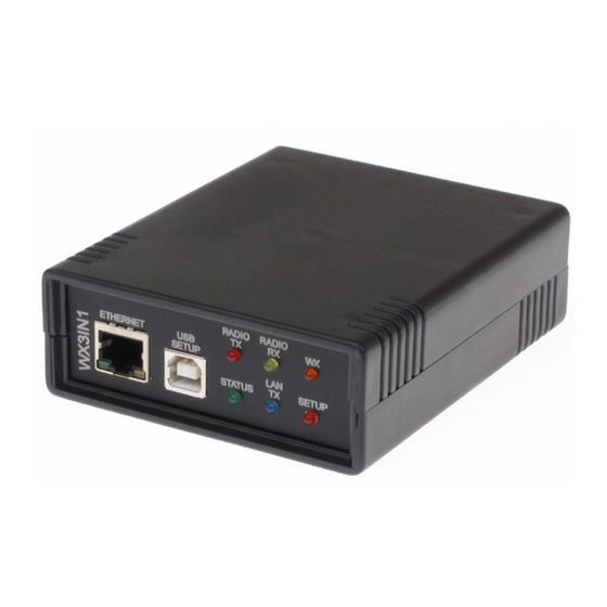
Summary of Contents for Microsat WX3IN1
- Page 1 WX3IN1 (v1.18) APRS DIGIPEATER APRS-IS CLIENT APRS-IS MESSAGES FORWARDING WEATHER STATION SERVER Instruction manual Configuration software manual Designer: Mateusz Płociński SQ3PLX Producer: Microsat info@microsat.com.pl...
-
Page 2: Table Of Contents
Table of Contents 1. Technical parameters................3 2. Device features..................3 2.1. APRS client / digipeater..............3 2.2. APRS-IS client..................3 2.3. APRS-IS messages forwarding..............4 2.4. Weather station server...............4 3. Connecting to weather station..............5 4. Connecting to radio................6 5. Connecting to PC...................7 6. Connectors and device status LEDs description..........8 7. -
Page 3: Technical Parameters
The main purpose of the device is receiving and sending data frames via APRS radio. WX3in1 is capable of receiving an APRS frame, decoding the sender, recipent, path and information field. Then actions are performed in accordance with the options... -
Page 4: Aprs-Is Messages Forwarding
WX3in1 allows you to receive weather information from the WS2300 and WS2350 stations via the RS-232 cable. The data is then encoded into the APRS frame and may be sent to a radio network at specified intervals. Additionally WX3in1 allows you to send the same frames to APRS-IS server. -
Page 5: Connecting To Weather Station
It is only necessary to calibrate the atmospheric pressure and reduce it to a value relative to sea level (WX3in1 sends an ABSOLUTE pressure value and not relative, which is not being calibrated in these models of weather stations). -
Page 6: Connecting To Radio
4. Connecting to radio Radio MINI DIN 6pin connector is placed on the rear panel of WX3in1. Pinout of this connector is described in the following figure. Connector pinout description: 1. RS-232/UART pin (currently not used), 2. APRS signal output from the device to the microphone input of radiotelephone. -
Page 7: Connecting To Pc
After connecting and powering, WX3in1 is detected in Windows as a new device, then system asks for the drivers that are available in the drivers directory of WX3in1 software package. After this, run the configuration software and select the COM port where the device is installed. -
Page 8: Connectors And Device Status Leds Description
6. Connectors and device status LEDs description There are 6 leds on the front panel that show the status of device operation. The following image shows the location of LEDs and their meaning. Radio TX - The red LED lights during transmission - the device sends an APRS data •... - Page 9 5.5-type power connector (center pin is a power supply plus) • Weather station (DB9) – Connects to weather station, • Radio - (mini din 6 pin) - Connects to radio. •...
-
Page 10: Description Of Configuration Software
7. Description of configuration software 7.1. Opening a connection After running the application, it is necessary to select the COM port of WX3in1 assigned by Windows. Then use OPEN PORT to connect to the device. 7.2. Reading configuration from the device... -
Page 11: Radio Settings
7.5. Radio Settings Below is the description of functions and their meanings: Callsign – The sign of our station with SSID extension. The default SSID is 0, • TX delay (ms) – The delay time TX / RX in milliseconds for sending packages. It is •... -
Page 12: Digipeater Settings
• forwarded, for example WIDEn-N with n>=1 and n<=3 will forward paths: WIDE1-1, WIDE2-2, WIDE2-1, WIDE3-3, WIDE3-2, WIDE3-1, Fourth column – if Yes, WX3in1 will add its own callsign to the path, if No, • it will not do that, Fifth column –... -
Page 13: Beacon Settings
• can choose a destination address of APNW01 or BEACON. When frames are sent with the path (eg, WIDE2-2), we can only choose APNW01 as a destination address, which identifies the device as WX3in1, DigiPath – APRS path, • Rate (min) – Parameter, expressed in minutes, in which we determine how often •... -
Page 14: I-Gate Settings
„_” - sign after coordinates is a symbol of our beacon station, object, etc., please • refer to the table of symbols at http://aprs.pl/ikony.htm, WX3in1 test - information field, here we can enter our information about the • station, beacon, etc. -
Page 15: Weather Reports Configuration
(with the exclusion of RFONLY, NOGATE, TCPIP) and sends them to the APRS- IS server, Gate msg from APRS-IS to RF – If selected WX3in1 will send messages received via • the Internet for sites that are heard in the APRS network (for which the RF frames were received by WX3in1 in the past 15 minutes), IP1, IP2, IP3 - APRS-IS servers addresses which WX3in1 will try to connect. -
Page 16: Rtc Clock Configuration
APRS-IS (minimum time - 5 minutes). 7.10. RTC clock configuration WX3in1 has an internal real time clock to store current date and time in case of power failure. The clock is used for the dating of the position, beacons, objects and weather reports sent via WX3in1.

Need help?
Do you have a question about the WX3IN1 and is the answer not in the manual?
Questions and answers