
Subscribe to Our Youtube Channel
Related Manuals for Seco SE 2000 Series

Summary of Contents for Seco SE 2000 Series
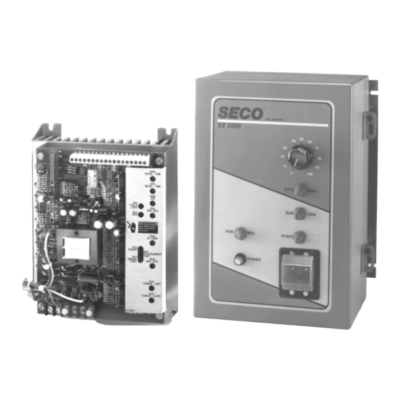
- Page 1 Installation & Operation Manual SECO SE 2000 Series DC Motor Controller ® 1 Through 5 HP 115/230 VAC 1 Phase Input...
-
Page 2: Table Of Contents
TABLE OF CONTENTS Section Page Section Page OPTIONS ........... GENERAL INFORMATION ....General Description ......Controller ..........5.1.1 Option Description ......Specifications ........START UP PROCEDURES ....INSTALLATION ........Field Excitation ........Power Unit Models ....... Control Voltage ........Controller Mounting ......2.2.1 Ambient Temperature ...... -
Page 3: General Information
SECO AC/DC Drive Representative. Always the operation of all major components in refer to SECO order number, model number and the system. Serious personal injury or serial number when contacting SECO AC/DC Drives. -
Page 4: Controller
1.1 CONTROLLER • Torque and Slope Control SECO Drives SE2000 series DC motor controllers are Precise setting of motor torque and slope control to designed to control shunt wound and permanent magnet DC motors from 1/4 to 5 HP. Versatile and... - Page 5 MODELS OPTIONS • Power Unit Only • 2 Pole Circuit Breaker Consists of control board, SCR power bridge, and Enables both input lines to be disconnected. Re- terminals. quired by some local Electrical Codes (std. on 3 & 5 HP models and on all enclosed units). •...
- Page 6 OPTIONS Factory Installed Field Installed Description Model Number Suffix Model Number 2 pole circuit breaker – enables both lines to be disconnected – required by some local electrical codes SE2999-1* Follower-Process Controller/DC Voltage Speed Control by external signal, 4-20 mA, 1-5 mA, 0-14 VDC, 0-100 VDC -2** SE2999-2** Follower-Pulse Tach-Generator-Speed Control by external...
-
Page 7: Specifications
1.2 SPECIFICATIONS Performance Characteristics Speed Range: 30:1 Speed Regulation (As % of Motor Base Speed) – For 95% Load Change Armature Voltage Feedback: ±2% Tachometer Feedback: ±1/2% (depending on tach generator) Acceleration/Deceleration Range A by current limit Range B 3-30 seconds Range C 0.3-3 seconds Operating Conditions... -
Page 8: Installation
2.0 INSTALLATION 2.1 POWER UNIT MODELS The procedure describes the installation of the SE2000 The Power Unit is intended to replace the Challenger controller. 8500, 8600 and 8800 Power Units. The mounting dimensions are identical to the Challenger Series. CAUTION Care should be taken to ensure the correct voltage settings are selected for the SE2000 depending on In cases where the motor speed controller is... -
Page 9: Controller Mounting
2.2 CONTROLLER MOUNTING From 8300/8800 Model SE2005 The SE2000 controller must be mounted in a vertical position. This orientation permits the required cooling of TB1-1 C8301 TB1A-AC1 the heat sinks. TB1-2 C8801 TB1A-AC2 Drill patterns and dimensions for the SE2000 controller TB1-1 C8303 TB1A-AC1... - Page 10 SE2000 Chassis Basis ON-Off or Run Brake Models Reversing Brake Models SE2000 Power Unit Enclosed Unit - All Models...
- Page 11 Dimensions in inches SE2000 1/4 - 2 HP Power Unit Layout...
- Page 12 Dimensions in inches SE2000 1/4 - 2 HP Chassis Layout Basic On Off Run Brake Rev Brake...
- Page 13 SE2000 1/4 - 2 HP Enclosed Layout Basic On Off Run Brake Rev Brake...
- Page 14 SE2000 3-5 HP Power Unit Layout Dimensions in Inches...
- Page 15 SE2000 3-5 HP Chassis Layout Basic On Off Run Brake Rev Brake Dimensions in inches...
- Page 16 SE2000 3-5 HP Enclosed Layout Basic On Off Run Brake Rev Brake Dimensions in inches...
-
Page 17: Mounting Clearances
SE2000 2.2.4 MOUNTING CLEARANCES CAUTION Adequate clearance should be allowed for easy access Follow the installation wiring diagram pro- to terminals and adjustments and to facilitate inspection vided in Figures 4-1 to 9. When connecting and maintenance. the motor, pay particular attention to the marking on the motor leads. - Page 18 Figure 2-3 Shunt Field Connections for D.C. Motors...
- Page 19 TABLE 3 PROGRAMMING JUMPERS/SWITCHES/ADJUSTMENT POTENTIOMETERS Location Function Position JUMPERS 90V Armature *180V Armature J2 - J3 115V Input Refer to Text *230V Input .3 - 3 Seconds Acceleration/Deceleration Range *3 - 30 Seconds Acceleration/Deceleration Range Current Limit Acceleration *Internal Jog Reference External Jog Reference SE2005 SE2002...
- Page 20 Figure 3-1 Adjustment Locations JUMPER, SWITCH AND ADJUSTMENT POTENTIOMETERS SHOWING FACTORY SETTINGS...
-
Page 21: Permanent Magnet Motors
If the motor has additional leads labeled P1 and P2 to drive the motor in either the Forward or Reverse (motor thermal switch) identified on SECO's drawings direction of rotation. The correct direction of rotation as MOT, connect these wires in series with the STOP must be selected by either a selector switch or by pushbutton. -
Page 22: Line Voltage Selection
Terminals 10 and 11 of TB2 serve as connector points 3.1.1 LINE VOLTAGE SELECTION for either an analog tachometer or a digital tach. Either SE2000 Series controllers are suitable for operation on polarity on the tachometer inputs can be used. See either 115 or 230 VAC single phase, 50/60 Hz supply. -
Page 23: Acceleration/Deceleration Times
3.1.9.2 ACCELERATION/DECELERATION 3.1.9.4 JOG TIMES Preset Jog speed may be set by adjusting R100, Jog potentiometer. Jumper J5 must be in the A position. The Acceleration and deceleration times are independently maximum adjustment for R100 is 100% of base motor adjustable by means of potentiometers R98 Accel and speed. -
Page 24: Relay Circuits
4.0 RELAY CIRCUITS 4.3 REVERSING BRAKE In the Reversing-Brake version of the SE2000 control- 4.1 POWER UNIT AND BASIC ON-OFF ler, the Forward-Reverse switch selects which contactor A Start-Stop relay K1 is mounted on the main control MF or MR is energized when the Start button is pressed board. - Page 25 Figure 4-2 2-Wire Start/Stop...
- Page 26 Figure 4-3 Line Start...
- Page 27 Figure 4-4 2-Wire Start/Stop with Memory Reversing * User Supplied operators Factory Supplied Jumper...
- Page 28 Figure 4-5 Reversing-Brake with R8006 Remote Operator Station * User Supplied operators Factory Supplied Jumper...
- Page 29 Figure 4-6 SE2000 Operator Connections for all Chassis or ENclosed (w/o operator) Rev-Brake Models...
- Page 30 Figure 4-7 SE2000 Operator Connections for Chassis, Power Unit or ENclosed (w/o operators) Basic On-Off or Run-Brake Models...
- Page 31 Figure 4-8 SE2000 Operator Connections for ENclosed (with operators) Basic On-Off Run-Brake Models...
- Page 32 Figure 4-9 SE2000 Operator Connections for ENclosed (with operators) Run-Brake Models...
-
Page 33: Options
5.0 OPTIONS 5.1 GENERAL DESCRIPTION The SE2000 Series has been designed for maximum flexibility and utility to fit the precise requirements of each specific application. To achieve this goal several options have been designed to enhance the standard SE2000 features and allow each user to purchase a system with only those features required by their appli- cation. -
Page 34: Start Up Procedures
2. Move Jumper J9 to the correct position 6.0 START UP PROCEDURES • For 7 VDC/1000 RPM Tach: J9 in B position The following procedures verify that the motor field excitation, AC control voltage, reference voltage, and • For 50 VDC/1000 RPM Tach: J9 in C position motor current are within tolerance and that direction of •... -
Page 35: Option Installation And Start-Up
6.6 OPTION INSTALLATION AND START-UP 6.7.4 ADJUSTMENTS The options for the SE2000 can be built in at the factory Internal adjustments must be made regardless of which when purchased or added as a field-installed option. mode is to be used. Mounting instructions will be included when shipped. -
Page 36: Input Connections
input range is 0.1V to 100V. In addition to magnetic 6.9 CONTROLLED DECELERATION STOP pulse tachometers, encoders and Hall Effect de- (-4/SE2999-4) See Figure 6-3 vices can be used. 6.9.1 SPECIFICATIONS 2. Output Signal: 0 to 10 VDC The Controlled Deceleration Stop option expands the 6.8.2 INPUT CONNECTIONS selection of stopping modes for the SE2000 by using two stop pushbuttons. -
Page 37: Connections
6.9.2 CONNECTION 6.11 ENHANCED TORQUE SLOPE A normally-open momentary contact Stop pushbutton or (-6/SE2999-6) contact is connected to TB4, positions 1 and 2. 6.11.1 FEATURES 6.10 FAULT MODULE (-5/SE2999-5) 1. Terminal connections for external torque and See Figure 6-4 slope pots for centerwind tension control. 6.10.1 SPECIFICATIONS 2. -
Page 38: Adjustment Procedure With Line Speed Signal
6.11.3 ADJUSTMENT PROCEDURE WITH 5. At max. line speed, adjust LS for balanced NULL LINE SPEED SIGNAL: LED's (SLOPE LED should be OFF). 6. As roll builds, adjust SLOPE CW to maintain desired tension. The Slope function is active when the 1. -
Page 39: Theory Of Operation
7.0 THEORY OF OPERATION 1) The correct top speed for a particular combination of tach generator and motor is set using the Max. Speed This chapter describes the operating theory of the pot. Note: The tachometer circuit must be physically SE2000 DC motor controller. -
Page 45: Troubleshooting
Do not assume the procedures listed here form a TROUBLESHOOTING complete safety list. They are only a basic starting point. This chapter contains troubleshooting information for • Always use appropriate high-voltage safety tech- the SE2000 packaged controller. The organization of niques when working on the equipment. -
Page 46: Troubleshooting Areas
• Commutator. Inspect the condition of the commuta- 8.3 TROUBLESHOOTING AREAS tor. A shiny and light brown surface generally indi- General troubleshooting areas that can be categorized cates good condition. If oil, grease or other foreign into the following groups: matter is noted, clean thoroughly. -
Page 47: Voltage Checks
8.4.1 VOLTAGE CHECK Using a VOM, check the voltages listed in Table 5. Take great care when connecting a meter to the points described to avoid short circuiting adjacent terminals. Table 5 Voltage Location Function 115 VAC 230 VAC Power L1-L2 AC Line Input 103-126 VAC... -
Page 48: Replacement Parts
9.0 REPLACEMENT PARTS It is intended that the SE2000 should be serviced by replacing major subassemblies. The Replacement Parts List lists all of the subassemblies required to service SE2000 drives. It is recommended that users keep these parts readily available to support the drive's critical applications.
Need help?
Do you have a question about the SE 2000 Series and is the answer not in the manual?
Questions and answers