
Subscribe to Our Youtube Channel
Related Manuals for Panasonic DMR-BW780EB


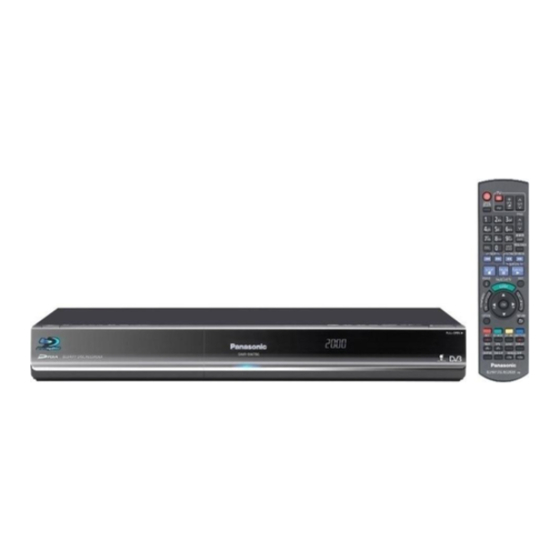
Summary of Contents for Panasonic DMR-BW780EB
- Page 1 ORDER NO.DSD1005030CE Blu-ray Disc Recorder DMR-BW780EB Model No. DMR-BW880EB Vol. 1 Colour (K).......Black Type © Panasonic Corporation 2010. Unauthorized copying and distribution is a violation of law.
-
Page 3: Table Of Contents
TABLE OF CONTENTS PAGE PAGE 1 Safety Precautions----------------------------------------------- 4 1.1. General guidelines ---------------------------------------- 4 2 Warning -------------------------------------------------------------- 5 2.1. Prevention of Electrostatic Discharge (ESD) to Electrostatic Sensitive (ES) Devices -------------- 5 2.2. Precaution of Laser Diode------------------------------- 6 2.3. Service caution based on legal restrictions --------- 7 3 Service Navigation ----------------------------------------------- 8 3.1. -
Page 4: Safety Precautions
1 Safety Precautions 1.1. General guidelines 1. When servicing, observe the original lead dress. If a short circuit is found, replace all parts which have been overheated or damaged by the short circuit. 2. After servicing, see to it that all the protective devices such as insulation barriers, insulation papers shields are properly installed. -
Page 5: Warning
2 Warning 2.1. Prevention of Electrostatic Discharge (ESD) to Electrostatic Sensitive (ES) Devices Some semiconductor (solid state) devices can be damaged easily by static electricity. Such components commonly are called Elec- trostatic Sensitive (ES) Devices. Examples of typical ES devices are integrated circuits and some field-effect transistor-sand semi- conductor "chip"... -
Page 6: Precaution Of Laser Diode
2.2. Precaution of Laser Diode... -
Page 7: Service Caution Based On Legal Restrictions
2.3. Service caution based on legal restrictions 2.3.1. General description about Lead Free Solder (PbF) The lead free solder has been used in the mounting process of all electrical components on the printed circuit boards used for this equipment in considering the globally environmental conservation. The normal solder is the alloy of tin (Sn) and lead (Pb). -
Page 8: Service Navigation
3 Service Navigation 3.1. How to format for HDD when replacement of HDD or Main P.C.B. 3.1.1. How to escape " HDD Error " indication on GUI display. 1. When exchange HDD or Main P.C.B., the " HDD Error " screen is displayed, but, according to a following procedure, please format HDD. -
Page 9: Service Information
3.2. Service Information 3.3. Caution for DivX... -
Page 10: Micro Fuse Conducting Check
3.4. Micro Fuse conducting check This unit uses the Micro Fuse. Check the Micro Fuse conducting using the Tester at the check points below. -
Page 11: Hdd/Bd Drive) Service Navigation
3.5. (HDD/BD Drive) Service Navigation 3.5.1. HDD/BD Drive Malfunction check (Simplified Method) Perform simple quality judgement process of HDD/BD Drive according to the following operations. 1. Execute Service Mode While the power is off, press [CH UP], [REC] and [OPEN/CLOSE] keys simultaneously for five seconds. 2. -
Page 12: Operation Check When A Usb Device Is Connected
3.6. Operation check when a USB device is connected You can check the operation status (normal or abnormal) of the USB connection part of this unit easily as shown below. Connect each device to the USB terminal on the front panel and check the operation status on the TV monitor. Normal operation: Automatically displayed when the USB connection is made to a digital camera, etc. - Page 13 Main functions 1. Execute Tuner Service Mode Turn the power on to receive digital broadcasting (HD broadcasting). Press and hold [POWER] (Unit Key) and press [OPEN/CLOSE] + [REC] for 5 seconds at the same time. 2. Finishing Service Mode Method 1: After turning the unit “OFF”, pull out the AC cord. Method 2: Repeat turning ON and OFF twice: P-OFF →...
- Page 14 Note: Hard test result does not guarantee that problems do not exist even if the result is OK. The result is used as reference when any trouble occurs. 3.7.2. Use times and number of times of Power ON/OFF Display accumulated time of Power ON and display number of times of Power ON/OFF. *1 : Display accumulated time of Power ON Display on a 15-minute basis 00123:15 →...
- Page 15 Operation procedure Preparation: Prepare a SD card to export data stored in this unit. Create the following directory on the SD card. EEPBAKSD Boot: 1. On Tuner Service Mode display Using Remote Controller, move the cursor to user’s setting information backup display position (Refer to below) on Tuner Service Mode display.
-
Page 16: Specifications
4 Specifications... -
Page 19: Location Of Controls And Components
5 Location of Controls and Components... -
Page 21: Installation Instructions
6 Installation Instructions 6.1. Taking out the Disc from BD-Drive Unit when the Disc cannot be ejected by OPEN/CLOSE button 6.1.1. Forcible Disc Eject 6.1.1.1. When the power can be turned off. 1. Turn off the power and press [STOP] [CH UP] keys on the front panel simultaneously for 5 seconds. 6.1.1.2. -
Page 22: Service Mode
7 Service Mode 7.1. Self-Diagnosis and Special Mode Setting 7.1.1. Self-Diagnosis Functions Self-Diagnosis Function provides information for errors to service personnel by “Self-Diagnosis Display” when any error has occurred. U**, H** and F** are stored in memory and held. You can check latest error code by transmitting [0] [1] of Remote Controller in Service Mode. Automatic Display on LCD will be cancelled when the power is turned off or AC input is turned off during self-diagnosis display is Error Code Diagnosis contents... - Page 23 Error Code Diagnosis contents Description Monitor Display Automatic LCD display The unit is carrying out its No display recovery process. Hang-up Displayed when communication error has No display occurred between Main microprocessor and Timer microprocessor. Displayed is left until the [POWER] key is pressed.
- Page 24 Error Code Diagnosis contents Description Monitor Display Automatic LCD display PLEASE Unit is in termination process Unit is in termination process now. No display WAIT “BYE” is displayed and power will be turned off. In case “Quick Start” of setup menu is ON, it is displayed in restoration operation for The character indication flows side- AC off.
- Page 25 7.1.2. Special Modes Setting Item LCD display Key operation Mode name Description Front Key Rating password The audiovisual level setting password is Open the tray, set DRIVE SELECT initialized to “Level 8”. to BD, and press [REC] and [PLAY] simultaneously for 5 seconds. Service Mode Setting every kind of modes for servicing.
- Page 26 Aging Overview • Record several programs onto the mounted HDD with DR mode until the recording capacity becomes full. Then play back all the recorded programs (including special playback). • When the remaining capacity becomes almost zero due to multiple recordings, the disc is formatted, recording is made onto the same disc again and playback starts.
- Page 27 Sequence 0: OPEN/CLOSE of BD drive tray Press [OPEN/CLOSE] to open the tray, then inserting discs. Press [OPEN/CLOSE] to close the tray. Sequence 1: Format of the HDD Sequence 2: Details of Record/ Playback HDD: Record/ HDD: Playback Sequence 3: Detail of copying. (HDD to BD) Recorded to the BD.
- Page 28 Item LCD display Key operation Mode name Description Front Key Demonstration lock/ Ejection of the disc is prohibited. *When lock the tray. When the power is on, press unlock The lock setting is effective until unlocking [STOP] and [POWER] keys simulta- the tray and not released by “Main unit ini- neously for 5 seconds in the condi- tialization”...
- Page 29 7.1.3. Service Modes at a glance Service mode setting: While the power is off, press REC, CH UP and OPEN / CLOSE simultaneously for five seconds. Item LCD display Key operation Mode name Description (Remote controller key) Release Items Item of Service Mode executing is can- Press [0] [0] in service mode.
- Page 30 Item LCD display Key operation Mode name Description (Remote controller key) READ SEEK Inspecting seek time of HDD to inspect per- At start Press [3] [1] in service mode. Inspection formance. * When canceling the inspection mode while executing, do “forced power-off”.
- Page 31 Item LCD display Key operation Mode name Description (Remote controller key) READ VERIFY Measure of access time in READ VERIFY At start Press [3] [2] in service mode. Inspection MODE of HDD. * When canceling the inspection mode while executing, do “forced power-off”.
- Page 32 Item LCD display Key operation Mode name Description (Remote controller key) Standard Speed Standard speed AV scan check of HDD Press [3] [6] in service mode. Scan * When canceling the inspection mode while executing, do “forced power-off”. Method: Press [POWER] key on the main unit more than 4 seconds.
- Page 33 Item LCD display Key operation Mode name Description (Remote controller key) HDD/BD Drive Simple Check if HDD Self-Diagnosis test was per- HDD Self-Diagnosis test start. Press [3][8] in service mode. Check formed or Drive last error occurred within 4 weeks. * If the current date or the date when the error occurred is wrong, correct judgement may not be made.
- Page 34 Item LCD display Key operation Mode name Description (Remote controller key) BD Drive Last Error BD Drive error code display. 1. Error Number is displayed for 5 Press [4] [2] in service mode. *For details about the drive error code, refer seconds.
- Page 35 Item LCD display Key operation Mode name Description (Remote controller key) BD-R DVD-ROM RAM (2.6GB) RAM (4.7GB) DVDR Others * is displayed the responded value from RTSC. 6. Disc Maker ID is displayed for 5 seconds. 7. Factor of Drive Error (hexadecimal) In case that the maker cannot be occurring is left displayed identified, display is black out.
- Page 36 Item LCD display Key operation Mode name Description (Remote controller key) : Error occurring disc situation Laser power confirmation Drive state is judged based on difference Measuring stars (Measuring in pro- into between laser power value at shipping and cess). BD Drive in service mode.
- Page 37 Item LCD display Key operation Mode name Description (Remote controller key) CEC (H) output Check of the CEC terminal high output of When the check is OK. Press [5] [5] in service mode. HDMI. When the check is NG. CEC (L) output Check of the CEC terminal low output of When the check is OK.
- Page 38 Item LCD display Key operation Mode name Description (Remote controller key) Tray OPEN/CLOSE Test The tray is opened and closed repeatedly. Press [9] [1] in service mode *When releasing this mode, press the [POWER] button of Remote Controller. “*” is number of open/close cycle times.
-
Page 39: Service Fixture & Tools
8 Service Fixture & Tools Part Number Description Compatibility RFKZ0557 Extension FFC (Digital P.C.B. - AV IO P.C.B. / 11 Pin) RFKZ0216 Extension Cable (Digital P.C.B. - Main P.C.B. / 23 Pin) Same as BS750/BS850EG Series RFKZ0323 Extension Cable (Digital P.C.B. - Main P.C.B. / 9 Pin) Same as BS750/BS850EG Series RFKZ0215 Extension Cable (Front (R) P.C.B. -
Page 40: Disassembly And Assembly Instructions
9 Disassembly and Assembly Instructions 9.1. Unit 9.1.1. Disassembly Flow Chart The following chart is the procedure for disassembling the casing and inside parts for internal inspection when carrying out the ser- vicing. To assemble the unit, reverse the steps shown in the chart below. 9.1.2. -
Page 41: Front Panel
9.1.3. Top Case 9.1.5. Front (L) P.C.B., Front (R) P.C.B. 1. Remove 2 Screws (A) and 3 Screws (B). 1. Remove 4 Screws (A) to remove the Front (L) and Front 2. Slide the Top Case rearward and open the both ends at (R) P.C.B. - Page 42 9.1.6. BD Drive 2. Attach the Tray Door Ass’y in order from • Insert the Long shaft in the hole. 1. Remove 4 Screws (A), BD Power Cable and Drive FFC to • Insert the shaft in the hole. remove BD Drive. CAUTION: 3.
- Page 43 9.1.7. 1. Remove 4 Screws (A), SATA Signal Cable and SATA Power Cable to remove HDD. 2. Put HDD up and down inversely so as not to give a shock to HDD. 3. Remove 4 Screws (B) to remove HDD from HDD Bracket.
- Page 44 Rear Panel, Fan Motor T2 Tuner Pack P.C.B. 9.1.8. 9.1.9. 1. Pull up the T2 Tuner Pack P.C.B. in the direction of the 9.1.8.1. Only Fan Motor arrow with pulling the Claw of PCB Holder. 1. Remove 2 Screws (A) and disconnect the Fan connector. 2.
- Page 45 Digital P.C.B. Main P.C.B. 9.1.10. 9.1.12. 1. Disconnect 3 FFCs. 2. Disconnect 3 connectors. 3. Remove 3 Screws (A) to remove Digital P.C.B. 1. Disconnect BD Power Cable. 2. Disconnect 3 connectors. 3. Remove 3 Screws (A) and Front Angle to remove Main P.C.B.
-
Page 46: Bd Drive
9.2. BD Drive 3. Pull the Tray to the direction of arrow until it can be. 9.2.1. Upper Base Ass’y 1. Remove 4 Screws (A), and push the Hook in. 4. Insert the Paper Clip into the hole in about 45 degree. Press the dotted part in the arrow direction and tilt the Paper Clip in lower left direction to pry the rib at the back. - Page 47 5. Insert the Paper Clip into the Tray as below figure, lift up 9.2.3. Pulley Gear, Belt the lever using the Paper Clip while pushing the dotted 1. Perform the step “9.2.2. Tray”. point of the Tray. 2. Push the post to the direction of arrow by using the slot- And remove the Tray.
- Page 48 9.2.4. Slide Cam 7. Remove the Slide Cam. 1. Perform the step “9.2.3. Pulley Gear, Belt”. 2. Remove the Sheet. 3. Open the connector lock, and disconnect the 4 FFCs. 4. Remove 2 Screws (B) and the Drive P.C.B. 9.2.5. Mid Gear, Drive Gear and Loading Motor 1.
- Page 49 9.2.6. Grease...
- Page 50 9.2.7. How to Clean the Lens of Optical Pick-UP Follow the “9.2.1. Upper Base Ass’y”...
- Page 51 Service hint If a defective phenomenon is “NO READ”, please try to clean TT (turn table) in the drive in according to the following procedure. 1. Blow off dust on TT by a blower. (Air must not blow to it strongly.) 2.
-
Page 52: Measurements And Adjustments
10 Measurements and Adjustments 10.1. Service Positions Note: For description of the disassembling procedure, see the section 9. 10.1.1. Checking and Repairing of Main P.C.B. - Page 53 10.1.2. Checking and Repairing of BD Drive...
- Page 54 10.1.3. Checking and Repairing of AV IO P.C.B.
- Page 55 10.1.4. Checking and Repairing of HDD...
- Page 56 10.1.5. Checking and Repairing of Digital P.C.B.
-
Page 57: Caution For Replacing Parts
10.2. Caution for Replacing Parts 10.2.1. Items that should be done after replacing parts * Note1: 10.2.2. Notice after replacing Digital P.C.B. or BD Drive Formatting the HDD is unnecessary after replacing Digital P.C.B. or BD Drive. [TM AV1] is displayed, once power OFF, and power ON again. -
Page 58: Standard Inspection Specifications After Making Repairs
No abnormality should be seen in the picture, sound or operation. the BD-RE (V2.0) and RAM discs. *Panasonic BD-RE (V2.0) and DVD-RAM discs should be used when copying and playback. If a problem is caused by a VCD, DVD-R, DVD-Video, Audio-CD, or No abnormality should be seen in the picture, sound or operation. -
Page 59: S1. About Indication Of The Schematic Diagram
"Standard-Playback" mode when there is no specify mode is mentioned. Model No. DMR-BW780EB 4.Although the voltage and waveform available on here is measured with standard frame, it may be differ from actual measurement due to modification of circuit and so on. -
Page 60: S2. Voltage And Waveform Chart
S2. Voltage and Waveform Chart Note) Indicated voltage values are the standard values for the unit measured by the DC electronic circuit tester (high-impedance) with the chassis taken as standard. Therefore, there may exist some errors in the voltage values, depending on the internal impedance of the DC circuit tester. S2.1. -
Page 61: S2.2. Av_Io P.c.b
S2.2. AV_IO P.C.B. <IC3001> <P3001> REF No. PIN No. REC REF No. PIN No. REC REF No. PIN No. REC IC3001 IC3004 P3002 12.4 12.4 12.4 IC3004 P3002 IC3001 IC3001 IC3004 P3002 12.4 12.4 12.4 IC3005 P3002 IC3001 IC3001 IC3005 P3002 IC3001 IC3005... -
Page 62: S2.3. Front_R_Lcd P.c.b
S2.3. Front_R_LCD P.C.B. S2.4. T2_Tuner Pack P.C.B. REF No. PIN No. REC REF No. PIN No. REC REF No. PIN No. REC REF No. PIN No. REC IC7201 IC8701 IC8702 IC8703 IC7201 IC8701 IC8702 IC8704 IC7201 IC8701 IC8702 IC8704 IC7201 IC8701 IC8702 IC8704... -
Page 63: S3. Block Diagram
Q14301 (DC-DC CONVERTER) (REG.X SW+5.9V) X SW +5.9V EXT UP SEL SYNC Q10102 OSC 9 (FEED BACK) EXT LO 11 Q14302 (REG.X SW+5.9V) QR10101 (S P SAVE :OFF) QR10103 COLD S P SAVE :OFF) DMR-BW780EB/BW880EB Power Supply Block Diagram (1/2) -
Page 64: S3.1.2. Power Supply Block Diagram (2
FROM TIMER BLOCK SECTION P6701 P58004 DIGITAL V OUT 3 P.C.B. P STANDBY IC1611 (REG. LCD +5V) V IN FROM TIMER BLOCK SECTION LCD+5V P7501 P7201 V OUT 4 FRONT(R) FL BSB ON P.C.B. IC59501- DMR-BW780EB/BW880EB Power Supply Block Diagram (2/2) -
Page 65: S3.2. Analog Video Block Diagram
< B > BIAS AV2 G P3002 P58003 GREEN < RGB CPSV > (EXT) AV2 G AV2 B AV2 G BLUE CLAMP AV2 V/Y VIDEO/Y AV2 B AV2 B CLAMP AV2 V/Y AV2 V/Y CLAMP DMR-BW780EB/BW880EB Analog Video Block Diagram... -
Page 66: S3.3. Analog Audio Block Diagram
AV2 LIN BUFF. Bias (EXT) AUDIO IN ch1(L) P3001 P58007 AV1 L OUT MUTE Mute JK4801 COAXIAL AUDIO OUTPUT JACK Q4801 COAXIAL JK4901 OPTICAL DIGITAL AUDIO OUT JACK FROM P58007 P3001 OPTIEC DIGITAL BLOCK SECTION DMR-BW780EB/BW880EB Analog Audio Block Diagram... -
Page 67: S3.4. Timer Block Diagram
P7001 P7202 P7201 P7501 P6702 P58005 COM0 KEY IN3 COM0 - COM3 PLAY CH UP COM3 S7505 S7502 P58006 P6703 P7501 P7201 LED BACK 45 P7001 P7202 LED BACK FRONT (L) P.C.B. Q7204 (BACK LIGHT DRIVE) DMR-BW780EB/BW880EB Timer Block Diagram... -
Page 68: S4. Schematic Diagram
SP_SAVE_L FRONT (R) P.C.B. PDIAG-[C] PDIAG-[C] CS0- CS0- CS1- CS1- DASP_NC1 DASP_NC1 DIGITAL P.C.B. P1601 DR 12V DR 12V DR GND DR GND DR GND DR GND DR 5V DR 5V DMR-BW780EB/BW880EB BD DRIVE MAIN P.C.B. Interconnection Schematic Diagram S-10... - Page 69 S-11...
-
Page 70: S4.2. Power (P) Schematic Diagram
S4.2. Power (P) Schematic Diagram DMR-BW780EB/BW880EB Power Section (Main P.C.B. (1/2)) Schematic Diagram (P) CAUTION: FOR CONTINUED PROTECTION AGAINST FIRE HAZARD, REPLACE ONLY WITH THE SAME TYPE 2A 250V FUSE. ATTENTION: POUR UNE PROTECTION CONTINUE LES RISQUES 2A 250V D' INCENDIE N' UTILISERQUE DES FUSIBLE DE MÉME TYPE 2A 250V. - Page 71 DMR-BW780EB/BW880EB Power Section (Main P.C.B. (1/2)) Schematic Diagram (P) COLD R14206 D1BDR027A135 L14203 G0A100ZA0045 DR_5V IC14201 Q14202 C0DBAYY00602 B1CHRD000024 C14205 C14219 F1H1H561A004 50V560P $(0.1) Vref/SS R14202 (CPH6350) 16K[G] D13201 ZA13202 XYN3+J8FJ B0JBSG000057 ZA13201 VSC5984 C14206 F1H1C104A071 (AL1061) 16V0.1 L13201 PW_X_SW12R3V...
- Page 72 1000 F1H1C104A071 16V0.1 IC12201 C0DAEYY00022 Q10102 #B3PBA0000454 D10102 D10101 B0ACCK000005 B0ACCK000005 R10103 $(4700) QR10101 B1GBCFNN0041 VariationCategory DMR-BS880EB DMR-BS780EB DMR-XS380EB DMR-BW880EB DMR-BW780EB DMR-XW380EB DMR-BW880EF DMR-BW780EF DMR-XW380EF DMR-BS885EG DMR-BS785EG DMR-XS F2B2W4700003 F2B2W4700003 F2B2W4700003 F2B2W4700003 F2B2W4700003 F2B2W4700003 C11107 F2B2W6800005 F2B2W6800005 F2B2W6800005 F2B2W6800005 F2B2W6800005 F2B2W6 │F2A2W470A150...
- Page 73 F2A1C222B727 F2A1C222B727 F2A1C222B727 F2A1C222B727 F2A1C222B727 F2A1C1020095 F2A1C1020095 F2A1C1020095 B0BA01400041 B0BA01400041 B0BA01400041 VWJ0795=5 VWJ0795=5 VWJ0795=5 G0A3R3J00003 G0A3R3J00003 G0A3R3J00003 5600[G] 5600[G] 5600[G] $[G4DYA0000205] $[G4DYA0000205] $[G4DYA0000205] ZA11302 XYN3+J8FJ G4DYA0000209 G4DYA0000209 G4DYA0000209 ZA13202 XYN3+J8FJ DMR-BW780EB/BW880EB Power Section (Main P.C.B. (1/2)) Schematic Diagram (P) S-15...
-
Page 74: S4.3. Sd/Dv/Usb/Front (S) Schematic Diagram
S4.3. SD/DV/USB/Front (S) Schematic Diagram DMR-BW780EB/BW880EB SD/DV/USB/Front Section (Main P.C.B. (2/2)) Schematic Diagram (S) S_P_SAVE_L PW_X_SW12R3V PW_XSW5R9V DR_P_ON_H LB3801 J0JBC0000011 LB3802 J0JBC0000011 LB3803 ERJ3GEY0R00V R3803 $(75) LCD 5.0V TK11150CSCL-G FL 3.3V TK11133CSCL-G IC1611 $[VWJ0795=5] K3841 ZJ3802 CN VOUT K9ZZ00001279 ZJ3801... - Page 75 DMR-BW780EB/BW880EB SD/DV/USB/Front Section (Main P.C.B. (2/2)) Schematic Diagram (S) P1601 BD-DRIVE to BD-DRIVE DR_12V CKE7508 DRGND DRGND CKE7505 DR_5V CKE7504 P1603 DVD-DRIVE to RED DRIVE DR_12V DR_12V DRGND DR_5V to HDD P1602 HDD-DRIVE K1KA04AA0301 CKD7501 DR_12V DRGND CKD7502 DRGND CKD7504...
- Page 76 QR7502 B1GDCFNN0024 Modify Category R7501 4700 Variation Type R7502 4700 DMR-BS880EB R7503 5600 DMR-BS780EB R7504 DMR-XS380EB R7505 DMR-BW880EB R7506 VWJ0795=5 DMR-BW780EB R7507 DMR-XW380EB R7508 270[DI] DMR-BW880EF R7510 DMR-BW780EF R7511 ERJ3GEY0R00V ERJ3GEY0R00V $[ERJ3GEY0R00V] DMR-XW380EF R7512 ERJ3GEY0R00V ERJ3GEY0R00V $[ERJ3GEY0R00V] DMR-BS885EG R7513 ERJ3GEY0R00V...
- Page 77 R7520 EVQ11A05R 2200 STOP S7503 EVQ11A05R R7511 R7512 R7513 R7514 PED Capacitor Delete Confidential 2009/ / Until CPRM KEY1 ZS6701 VFV0164 HDD CPRM KEY1 ZS6702 VFV0167 MAC ADDRESS1 ZS6703 VFV0179 DMR-BW780EB/BW880EB SD/DV/USB/Front Section (Main P.C.B. (2/2)) Schematic Diagram (S) S-19...
-
Page 78: S4.4. Av_Io Schematic Diagram
S4.4. AV_IO Schematic Diagram DMR-BW780EB/BW880EB AV_IO Schematic Diagram R4090 R4046 R4055 C4063 R4076 R4077 D4005 Q4006 C4060 R4078 Q4007 R4079 D4006 R4088 C4057 R4089 R4093 C4064 R4057 R4047 R4081 R4080 IC4002 PS11R6V (PQ200WNA1ZPH) L4001 R4066 R4001 R4067 C4072 K4002 0[22]... - Page 79 DMR-BW780EB/BW880EB AV_IO Schematic Diagram VariationCategory BS880EB/BW880EB BS780EB/BW780EB XS380EB/XW380EB C4001 F2A1E221A643 F1H1C104A071│ C4002 F1H1C104A001│ F1H1C104A041 C4003 F1J1C105A091 C4056 F2A1C101B299 C4057 F1H1H3300005 C4060 F1H1H3300005 C4063 F2A1C470B174 F2A1E470A205 F2A1E470A205 C4064 F2A1C470B174 F2A1E470A205 F2A1E470A205 C4072 F2A1E221A643 C3906 C4092 F0A2E103A012 F1H1H471A792 C4801 F2A1E470A205 F2A1E470A205 F1H1C104A071...
- Page 80 PW_XSW12R3V FRONT_V_IN R3010 PW_XSW12R3V 75[22] P_SAVE_L RGB_CPS_V_IN CK3208 DGND AV2_BLANKING AV2_8 R4901 D4001 Q4001 B0JCDD000001 B1ADLB000006 C4901 F1H1A105A028 LB4901 J0JGC0000020 K4001 OPT_5V $[ERJ3GEY0R00V] QR4001 B1GBCFJJ0040 C4802 R4803 Q4801 C4803 R4806 R4802 C4801 R4804 R4807 R4805 DMR-BW780EB/BW880EB AV_IO Schematic Diagram S-22...
- Page 81 C3020 C3022 F1J1C1060001 F1J1C1060001 ZJ3001 K9ZZ00001279 ZJ3002 K9ZZ00001279 D4001 Q4001 R3009 C3066 C3069 B0JCDD000001 B1ADLB000006 C3024 5600 F1H1A105A028 F1H1A105A028 F1H1H682A013 PS5V AVIO_5V K4001 $[ERJ3GEY0R00V] IC3004 C0DBGYY00319 (S-1132B50-M5T1G) Confidential QR4001 B1GBCFJJ0040 2010/ 8/31 Until L3001 G1C100K00031 DMR-BW780EB/BW880EB AV_IO Schematic Diagram S-23...
-
Page 82: S4.5. Front_L Schematic Diagram
TO LED_REC1 TO LED_SD R7237 C7204 OPEN/CLOSE R7238 F1H1C104A071 R7239 C7206 F1H1C104A071 IR7201 PNA4861M02VT (H=7.0mm) Confidential Until 2010/8/31 R7211 R7241 [PR] LCD HOLDER CH,KAOMA? 120[22] Confidential R7240 Until 3300 [ES1] R7242 DMR-BW780EB/BW880EB DMR-BW780EB/BW880EB Front_L Front_R_LCD Schematic Diagram Schematic Diagram S-24... - Page 83 S-25...
-
Page 84: S4.7. T2_Tuner Schematic Diagram
S4.7. T2_Tuner Schematic Diagram DMR-BW780EB/BW880EB T2_Tuner Schematic Diagram C8778 F1G1H2200001 C8779 F1G1H2200001 C8780 F1G1H2200001 C8781 F1G1H2200001 OFDM_main 1R2V PW_TN1R2V CL8705 IC8701 C8704 F1G1A1040006 C1AB00003273 C8703 F1G1A1040006 C8709 (CXD2820R) F1G1A104 LB8713 C8710 J0JHC0000032 CL8706 PW_SW1R2V_T1 F1G1A1040 CL8707 CL8708 C8711 CL8709 F1G1A104... - Page 85 DMR-BW780EB/BW880EB T2_Tuner Schematic Diagram R8741 ANT 5V 2nd IC8705 R8758 C8766 VOUT ANT 5V 1st F1H1H103A219 C8778 F1G1H2200001 IC8703 C0CBCDD00004 C8779 F1G1H2200001 (TK11150CSCL-G) C8780 F1G1H2200001 C8749 6.3V C8781 F1G1H2200001 C8767 F1J0J106A020 F1H1A105A028 LB8701 C8750 J0JGC0000020 C8751 C8762 F1H1A105A028 LB8702 $[F1J0J106A020]...
- Page 86 R8719 C8744 C8732 F1G1A1040006 F1G1A1040006 LB8714 J0JHC0000032 PW_SW1R2V_T2 R8724 $(1k) R8721 X8702 H0J410500001 C8769 $[F1G1H2200001] C8770 $[F1G1H2200001] C8771 $[F1G1H2200001] C8772 $[F1G1H2200001] C8773 $[F1G1H2200001] C8775 $[F1G1H2200001] C8776 $[F1G1H2200001] PW_XSW3R8V CL8722 C8777 $[F1G1H2200001] PW_XSW1R8V CL8721 R8713 $[ERJ2GEJ103X] DMR-BW780EB/BW880EB T2_Tuner Schematic Diagram S-28...
- Page 87 L8705 F1H1H103A219 $[F1H1H103A219] C8742 G1CR22JA0020 C8790 C8800 F1G1A1040006 L8706 $[F1H1H8R0A016] F1G1H150A444 C8743 G1CR22JA0020 C8791 $[F1H1H8R0A016] F1G1A1040006 R8731 $[F1G1A1040006] C8744 F1G1A1040006 G1CR22JA0020 R8732 $[F1G1A1040006] G1CR22JA0020 R8724 $(1k) 8721 X8702 H0J410500001 Confidential Until 2010/09/30 ZA8701 RMN0899 [PR] DMR-BW780EB/BW880EB T2_Tuner Schematic Diagram S-29...
-
Page 88: S5. Print Circuit Board
S5. Print Circuit Board S5.1. Main P.C.B. DMR-BW780EB/BW880EB Main P.C.B. (Component Side) S-30 S-30... - Page 89 DMR-BW780EB/BW880EB Main P.C.B. (Foil Side) S-31 S-31...
- Page 90 (Component Side) DMR-BW780EB/BW880EB Main P.C.B. (Component Side) S-32...
- Page 91 (Foil Side) DMR-BW780EB/BW880EB Main P.C.B. (Foil Side) S-33...
-
Page 92: S5.2. Av_Io P.c.b
S5.2. AV_IO P.C.B. S5.2.1. AV_IO P.C.B. (Component Side) JK3901 C4072 JK4901 JK3001 JK4801 JK3002 C4092 C4001 C4064 P3001 C4063 P3002 ZJ3002 C4019 C4014 C4008 (Component Side) DMR-BW780EB/BW880EB AV_IO P.C.B. (Component Side) S-34... -
Page 93: S5.2.2. Av_Io P.c.b. (Foil Side
W241 IBT102 CK3108 R3009 C4022 W231 W232 IBT94 C4021 C3067 R3006 CKC56 C3068 C4017 C4020 IBT68 C3014 CKC51 W238 C4007 R3011 C3015 C4012 IBT72 W239 IBT95 IBT96 IBT97 C3016 C4016 IBT75 IBT76 (Foil Side) DMR-BW780EB/BW880EB AV_IO P.C.B. (Foil Side) S-35... -
Page 94: S5.3. Front_L P.c.b
S5.3. Front_L P.C.B. (Foil Side) (Component Side) DMR-BW780EB/BW880EB Front_L P.C.B. S-36... -
Page 95: S5.4. Front_R_Lcd P.c.b
S5.4. Front_R_LCD P.C.B. (Component Side) (Foil Side) DMR-BW780EB/BW880EB Front_R_LCD P.C.B. S-37... -
Page 96: S5.5. T2_Tuner Pack P.c.b
C8732 C8719 X8701 R8709 R8731 R8708 C8820 R8732 R8724 R8725 TU8701 X8702 R8720 CL8722 C8727 C8723 LB8714 C8747 C8776 C8804 LB8722 C8777 C8775 C8773 R8713 LB8716 LB8721 CL8723 PS8702 PS8703 CL8721 (Component Side) DMR-BW780EB/BW880EB T2_Tuner Pack P.C.B. (Component Side) S-38... -
Page 97: S5.5.2. T2_Tuner Pack P.c.b. (Foil Side
R8769 R8743 C8794 CL8703 R8760 C8796 R8706 C8750 R8764 C8749 C8802 R8739 R8765 R8723 C8728 R8722 C8816 C8784 L8706 C8758 C8760 C8785 L8705 R8740 C8786 LB8712 C8757 C8759 C8761 C8815 R8737 (Foil Side) DMR-BW780EB/BW880EB T2_Tuner Pack P.C.B. (Foil Side) S-39... - Page 98 S-40...
-
Page 99: S6. Abbreviation
S6. Abbreviation INITIAL/LOGO ABBREVIATIONS A0~UP ADDRESS ACLK AUDIO CLOCK AD0~UP ADDRESS BUS ADATA AUDIO PES PACKET DATA ADDRESS LATCH ENABLE AMUTE AUDIO MUTE AREQ AUDIO PES PACKET REQUEST AUDIO RF SERVO AMP INVERTED INPUT SERVO AMP OUTPUT ASYNC AUDIO WORD DISTINCTION SYNC BIT CLOCK (PCM) BCKIN BIT CLOCK INPUT... - Page 100 INITIAL/LOGO ABBREVIATIONS DREQ DATA REQUEST DRESP DATA RESPONSE DIGITAL SERVO CONTROLLER DSLF DATA SLICE LOOP FILTER DIGITAL VIDEO DISC ERROR TORQUE CONTROL ERROR TORQUE CONTROL REFERENCE ENCSEL ENCODER SELECT ETMCLK EXTERNAL M CLOCK (81MHz/40.5MHz) ETSCLK EXTERNAL S CLOCK (54MHz) FBAL FOCUS BALANCE FCLK FRAME CLOCK...
- Page 101 INITIAL/LOGO ABBREVIATIONS PWMCTL PWM OUTPUT CONTROL PWMDA PULSE WAVE MOTOR DRIVE A PWMOA, B PULSE WAVE MOTOR OUT A, B READ ENABLE RFENV RF ENVELOPE RF PHASE DIFFERENCE OUTPUT (CD-ROM) REGISTER SELECT RSEL RF POLARITY SELECT RESET RESERVE SBI0, 1 SERIAL DATA INPUT SBO0 SERIAL DATA OUTPUT...
- Page 102 INITIAL/LOGO ABBREVIATIONS TPSO OP AMP OUTPUT TPSP OP AMP INVERTED INPUT TRCRS TRACK CROSS SIGNAL TRON TRACKING ON TRSON TRAVERSE SERVO ON VBLANK V BLANKING COLLECTOR POWER SUPPLY VOLTAGE VCDCONT VIDEO CD CONTROL (TRACKING BALANCE) DRAIN POWER SUPPLY VOLTAGE VIDEO FEED BACK VREF VOLTAGE REFERENCE SOURCE POWER SUPPLY VOLTAGE...
-
Page 103: S7. Replacement Parts List
S7. Replacement Parts List Note: 1.* Be sure to make your orders of replacement parts according to this list. 2. IMPORTANT SAFETY NOTICE Components identified with the mark have the special characteristics for safety. When replacing any of these components, use only the same type. 3. - Page 104 DMR-BW780EBK,DMR-BW880EBK vol.1 Ref.No. Part No. Part Name & Description Remarks Ref.No. Part No. Part Name & Description Remarks D14302 B0JCMD000014 DIODE 1 E.S.D. RFKB71181ET MAIN P.C.B. 1 BW780EBK (RTL) E.S.D. RFKB71181DT MAIN P.C.B. 1 BW880EBK (RTL) E.S.D. F11101 K5G202Y00006 FUSE VEP73177B AV IO P.C.B.
- Page 105 DMR-BW780EBK,DMR-BW880EBK vol.1 Ref.No. Part No. Part Name & Description Remarks Ref.No. Part No. Part Name & Description Remarks R7512 ERJ3GEY0R00V 1/10W 0 ZA15302 K9ZZ00001279 EARTH PLATE R7513 ERJ3GEY0R00V 1/10W 0 R7518 ERJ3GEY0R00V 1/10W 0 ZJ3801 K9ZZ00001279 EARTH PLATE R7519 ERJ3GEYJ222V 1/10W 2.2K ZJ3802 K9ZZ00001279 EARTH PLATE...
- Page 106 DMR-BW780EBK,DMR-BW880EBK vol.1 Ref.No. Part No. Part Name & Description Remarks Ref.No. Part No. Part Name & Description Remarks C4064 F2A1E470A205 25V 47U 1 BW780EBK R3905 ERJ3GEYJ473V 1/10W 47K C4072 F2A1E221A643 25V 220U 1 BW880EBK R3906 ERJ3GEY0R00V 1/10W 0 C4082 F1H1H102A004 50V 1000P R3907 ERJ3GEYJ473V 1/10W 47K C4083...
- Page 107 DMR-BW780EBK,DMR-BW880EBK vol.1 Ref.No. Part No. Part Name & Description Remarks Ref.No. Part No. Part Name & Description Remarks W216 ERJ6GEY0R00V 1/8W 0 R7238 ERJ3GEYJ101V 1/10W 100 W217 ERJ3GEY0R00V 1/10W 0 R7239 ERJ3GEYJ101V 1/10W 100 W218 ERJ8GEY0R00V 1/4W 0 R7240 ERJ3GEYJ332V 1/10W 3.3K W219 ERJ8GEY0R00V 1/4W 0 R7241...
- Page 108 DMR-BW780EBK,DMR-BW880EBK vol.1 Ref.No. Part No. Part Name & Description Remarks Ref.No. Part No. Part Name & Description Remarks C8762 F1H1H103A219 50V 0.01U LB8712 J0JYC0000070 COIL C8763 F1H1A105A028 10V 1U LB8713 J0JHC0000032 COIL C8764 F1H1A105A028 10V 1U LB8714 J0JHC0000032 COIL C8765 F1G1C1030008 16V 0.01U LB8715 J0JGC0000020 COIL...
- Page 109 DMR-BW780EBK,DMR-BW880EBK vol.1 Ref.No. Part No. Part Name & Description Remarks Ref.No. Part No. Part Name & Description Remarks X8702 H0J410500001 CRYSTAL OSCILLATOR ZA8701 RMN0899 GND ANGLE S-51...
- Page 110 DMR-BW780EBK,DMR-BW880EBK vol.1 Ref.No. Part No. Part Name & Description Remarks Ref.No. Part No. Part Name & Description Remarks RHD30162 SCREW VXY2077-A BD DRIVE UNIT RHD30162 SCREW L6FAJBYG0001 FAN MOTOR RHD30162 SCREW RFKB71181ET MAIN P.C.B. 1 BW780EBK (RTL) E.S.D. RHD34001 SCREW RFKB71181DT MAIN P.C.B.
- Page 111 DMR-BW780EBK,DMR-BW880EBK vol.1 Ref.No. Part No. Part Name & Description Remarks Ref.No. Part No. Part Name & Description Remarks RYP1573E-K FRONT PANEL ASS'Y1 1 BW780EBK RYP1573-K FRONT PANEL ASS'Y1 1 BW880EBK 28-1 RMH0209 MAGNET 28-2 RMH0209 MAGNET 28-3 RDG0639 DAMPER 28-4 RHD26045 SCREW 28-5...
- Page 112 DMR-BW780EBK,DMR-BW880EBK vol.1 Ref.No. Part No. Part Name & Description Remarks Ref.No. Part No. Part Name & Description Remarks VDG1713-J PULLEY GEAR VDG1714 MID GEAR VDG1715-J DRIVE GEAR VEM0881 LOADING MOTOR U VHD1653-1 SCREW VMD6134 MECHA CHASSIS VMD5749 SLIDE CAM VMG1809 BELT VMT1982 DUST COVER B...
- Page 113 DMR-BW780EBK,DMR-BW880EBK vol.1 Ref.No. Part No. Part Name & Description Remarks Ref.No. Part No. Part Name & Description Remarks K2CT2YY00003 POWER CORD UK K1TWACC00003 RF COAXIAL CABLE N2QAYB000473 REMOTE CONTROLLER A4-1 100300037800 BATTERY COVER RPF0501 ACCESSORY BAG RPF0500 PE-BAG VQT2J65 OPERATING INSTRUCTIONS RPQ2704 RPG9162 PACKING CASE...
-
Page 114: S8. Exploded View
S8. Exploded View S8.1. Frame and Casing Section (1) (BW880) (BW880) (BW880) (BW880) (BW780) (BW880) (BW780) (BW780) (BW880) (BW780) (BW880) (BW880) S-56... -
Page 115: S8.2. Frame And Casing Section (2
S8.2. Frame and Casing Section (2) 31-2 31-1 28-1 28-5 28-5-2 28-2 28-4 28-3 28-5-3 28-6-1 28-5-1 28-6 28-6-2 S-57... -
Page 116: S8.3. Mechanism Section
S8.3. Mechanism Section S-58... -
Page 117: S8.4. Packing Parts And Accessories Section
S8.4. Packing Parts and Accessories Section A4-1 A8, A9 BATTERY (REMOTE CONT.) S-59...
Need help?
Do you have a question about the DMR-BW780EB and is the answer not in the manual?
Questions and answers