Table of Contents
Advertisement
FRANCE
SAMES Technologies. 13 Chemin de Malacher 38243 Meylan Cedex
Tel. 33 (0)4 76 41 60 60 - Fax. 33 (0)4 76 41 60 90 - Email : info@sames.com (www.sames.com)
USA
SAMES Technologies Inc. 11998 Merriman Road, Livonia, Michigan, 48 150
Tel. (734) 261.5970 - Fax. (734) 261.5971 - Email : samesinc@sames.com (www.sames.com)
Revised : A
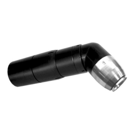
PPH 607 rotary atomizer,
bellcup 65 EC
P/N 1516592
User manual
Robotic single circuit with regulator
metric fittings
1
6301
Advertisement
Table of Contents

Summary of Contents for Sames PPH 607
- Page 1 FRANCE SAMES Technologies. 13 Chemin de Malacher 38243 Meylan Cedex Tel. 33 (0)4 76 41 60 60 - Fax. 33 (0)4 76 41 60 90 - Email : info@sames.com (www.sames.com) SAMES Technologies Inc. 11998 Merriman Road, Livonia, Michigan, 48 150 Tel.
- Page 2 SAMES Technologies is prohibited. All descriptions and characteristics given in this user manual are not contractually binding and SAMES Technologies reserves the right to modify this equipment without prior notice. © SAMES Technologies 2002...
-
Page 3: Table Of Contents
2. Introduction to atomizer - - - - - - - - - - - - - - - - - - - - - - - - - - - - - - - - 12 2.1. PPH 607, single circuit with regulator ....12 2.2. - Page 4 7.4. Nano-valve clean up ....... . 70 8. PPH 607 SCAR metric spare parts list - - - - - - - - - - - - - - - - - - - - - 71 8.1.
- Page 5 • When disassembling and assembling the rotary atomizer, make sure the atomizer cannot slip out of your hands. Take appropriate measures such as wearing rubber gloves and being assisted by a second person. • Make sure the PPH 607 is correctly assembled before operating the equipment. Revised A 6301...
- Page 6 • Ensure high voltage is “shut off” when servicing in the spray booth. • Prior to working on the PPH 607 make sure that the turbine has come to a complete stop. Make sure that no one can start the turbine while it is being worked on.
-
Page 7: Safety Warnings And Warranty Limits
• Metal containers, properly grounded, should be used for cleaning solvents. • The mechanical and electrical properties of the SAMES Technologies high voltage electrostatic generators and atomizers are designed to reduce this risk of sparks. The HV applicator must main- tain at least a 1 inch per 10kV, distance from ground. - Page 8 Foreword This paragraph contains information that an operator should know and understand before using the PPH 607. The purpose of this information is to indicate precautions that must be taken to prevent potentially serious damage to the atomizer. Bearing air filtration The air has to be suitably filtered to ensure a long lifetime and to prevent any contamination during paint...
- Page 9 45,000 rpm. Vibrations: If the PPH 607 vibrates abnormally, this generally means the rotating parts are unbalanced. There may be dry paint deposits on the bellcup, or it might be physically damaged or dry paint might be trapped between the injector and the clip. There also may be paint on the groove receiving the clip or on the clip itself causing unbalance.
- Page 10 Only use o-rings as specified in this manual. In the case of solvent borne materials, wetted rings are chemically inert to prevent any swelling or chemical deterioration. The proper operation of the PPH 607 is warranted only if used with the right size and material rings. Mechanical crash : The warranty does not apply to damages resulting from environmental causes: for example in case of a robot crashing.
- Page 11 The SAMES Technologies PPH 607 atomizer is covered by a 12-months warranty (two eight hours working shift). In addition, the warranty covers 10,000 hours of operation for the PPH 607 bearing air turbine. The warranty does not apply to wearing parts such as bellcups, removable regulator components, clips, and o-rings.
-
Page 12: Introduction To Atomizer
The PPH 607 rotary atomizer is designed for use in an automatic electrostatic spraying environment which requires equipment with fast and simple maintenance qualities. Equipped with a magnetic air bearing turbine, the PPH 607 is designed to atomize and apply various types of paints at a maximum loaded rotation speed of 45,000 RPM. -
Page 13: Parts Description And Functions
2. Introduction to atomizer (continued) 2.2. Parts description and functions Parts Function Bellcup Designed to atomize various types of paints. Specific bellcup design is selected by the type of product being sprayed. Turbine motor Designed as a high speed, durable, bearing-less drive motor; the turbine is responsible for rotating the bellcup. -
Page 14: Technical Characteristics
3. Technical characteristics 3.1. Dimensions (mm) TCP @ 300mm TCP @ cup TCP @300 mm Installed cups 65 EC cup 60 mm, Negative edge 70 mm, Vortex Note: GC = gravity center TCP = Tool center point Revised A 6301... -
Page 15: Working Characteristics
3. Technical characteristics (continued) 3.2. Working characteristics Weight US units Metric units Atomizer without cables or hoses 7.716 lbs 3.5 kg Body only 2.97 lbs 1.35 kg Bellcup with deflector 0.09 lbs 0.04 kg Turbine 0.925 lbs 0.420 kg Nano-valve 0.013 lbs 0.006 kg UHT 153 cascade... - Page 16 0 to 600 Nl/min. (21.18CFM) according to type of shaping air ring being used Turbine Refer to the following charts Air use for PPH 607 with load (SLPM) with 65EC bellcup. Solvent borne paint Viscosity: 28 seconds - Ford cup # 4 x 1000...
- Page 17 3. Technical characteristics (continued) 3.2 Working characteristics (continued) Turbine drive air consumption UNLOADED (relative to bellcup used) Vortex Negative edge Bearing air (k Rpm) bellcup bellcup (L/min.) (L/min.) (L/min.) Vortex bellcup Negative edge bellcup Bearing air K rpm (K tr/mn) Revised A 6301...
- Page 18 3. Technical characteristics (continued) 3.2 Working characteristics (continued) Turbine drive air consumption LOADED as per 75 cc/min bellcup used Viscosity: 60 seconds @ 80° F - Ford cup # 4 Fluid flow 75cc/min. Vortex Negative Rev. bellcup edge bellcup (k Rpm) l/min.
- Page 19 3. Technical characteristics (continued) 3.2 Working characteristics (continued) Turbine drive air consumption LOADED as per bellcup used Viscosity: 60 seconds @ 80° F - Ford cup # 4 Vortex bellcup Dia. 70 mm Negative edge bellcup Dia. 60 mm 75 cc/min. Vortex bellcup 75 cc/min.
- Page 20 3. Technical characteristics (continued) 3.2 Working characteristics (continued) Turbine drive air consumption LOADED relative as per bellcup used Viscosity: 25 sec. Ford cup # 4 @ 80°F (27°C) Fluid flow 75cc/min. Vortex Negative Rev. bellcup edge bellcup (k Rpm) l/min. (l/min.) Vortex bellcup Negative edge bellcup...
- Page 21 3. Technical characteristics (continued) 3.2 Working characteristics (continued) Turbine drive air consumption LOADED as per bellcup used Viscosity: 25 sec. Ford cup # 4 @ 80°F (27°C) Fluid flow 300cc /min. Vortex Negative Rev. bellcup edge bellcup (k Rpm) (l/min.) (l/min.) Vortex bellcup Negative edge bellcup...
- Page 22 3. Technical characteristics (continued) 3.2 Working characteristics (continued) Turbine drive air consumption LOADED relative as per bellcup used Viscosity: 44.7 sec. Ford cup # 4 @ 80°F (27°C) 75 cc/min Fluid flow 75cc/min. Vortex Negative Rev. bellcup edge bellcup (k Rpm) (l/min.) (l/min.) Vortex bellcup...
- Page 23 3. Technical characteristics (continued) 3.2 Working characteristics (continued) Turbine drive air consumption LOADED relative as per bellcup used (continued) Viscosity: 44.7 sec. Ford cup # 4 @ 80°F (27°C) Negative edge bellcup Dia. 60 mm Vortex bellcup Dia. 70 mm 75 cc/min.
-
Page 24: Operating Principle
3.3. Operating principle 3.3.1. Turbine rotation speed The reading is obtained using a microphone. The air supply arrives at the clip holding the bellcup. This clip is machined with a groove in which air passes with every rotation of the bellcup. This pres- sure variation causes a noise or “frequency signal”, which is sent through the injector holder to a microphone. -
Page 25: Turbine Motor
3.3 Operating principle (continued) 3.3.3. Turbine Motor The bearing air flows uniformly to the surface of the stator creating an air cushion which separates the rotor from the stator. The balance between air pressure and electromagnetic forces enables the rotor to float freely while maintaining its center above the stator. Drive air is used to accelerate the turbine through the turbine drive vane which is attached to the rotor. -
Page 26: Diagrams
4. Diagrams 4.1. General OD 6/8 NYLON Compensation air OD 8/10 NYLON OD 4/6 NYLON Shaping air OD 6/8 NYLON Bearing air OD 8/10 NYLON OD 4/6 NYLON Turbine brake OD 6/8 PFA Turbine drive OD 2,7/4 NYLON OD 2,7/4 NYLON Microphone IN OD 6/8 PFA Dump valve 1... -
Page 27: External Bellcup Wash
4. Diagrams (continued) 4.3. External bellcup wash External bellcup wash solvent or air External bellcup wash pilot air 31: Bellcup wash, solvent/air supply, cleans the D:2,7/4 PFA OD 3/16" PFA bellcup. D:2,7/4 Nylon OD 3/16" NYLON Magnetic turbine 4.4. Injector wash Injector wash pilot Injector wash solvent or air D:2,7/4 Nylon... -
Page 28: Microphone Air
4. Diagrams (continued) 4.5. Microphone air Microphone supply air is set by use of a remote regulator. D:4/6 Nylon OD 1/4" NYLON Microphone IN Microphone OUT D:4/6 Nylon OD 1/4" NYLON Magnetic turbine 4.6. Turbine drive Turbine drive air is controlled through a remote transducer. D:4/6 Nylon OD 1/4"... -
Page 29: Shaping Air
4. Diagrams (continued) 4.7. Shaping air D:8/10 Nylon OD 3/8" NYLON Shaping air 24: The shaping air supply controls the pattern size diameter and is controlled through a remote transducer. Magnetic turbine 4.8. Compensation air D:6/8 Nylon OD 5/16" NYLON Compensation air 25: Compensation air stops shaping air shroud con- tamination and is controlled through a remote... -
Page 30: Color Change And Circuit Flushing Examples
4. Diagrams (continued) 4.9. Color change and circuit flushing examples • Standard conditions: 90 psi (6 bars) air, solvent and paint. • Color change block and rinsing block distance to the atomizer (3 to 5 ft - 1 to 1.5 meter). Color change cycle Seconds Main Air... -
Page 31: Maintenance
5. Maintenance 5.1. Shut down / Start up procedures Important recommendations Follow the compressed air settings as described in section 3.2. The rotor and the stator will be damaged if the bearing air is turned off. Bearing air must be set at 90 PSI (6 bars) minimum at the quick disconnect plate. (*For tubing lengths over 15’, measure air pressure at the quick disconnect to determine correct setting.) Make sure that there is a signal emitting from the speed board. -
Page 32: Tools
5. Maintenance (continued) 5.2. Tools Sale USA P/N Sames P/N Tool description unit 1308689 1308689 Tool, aluminium cover, nut and quick discon- nect tightening ring removal Sale USA P/N Sames P/N Tool description unit 72-1107-00 1517728 Tool, 65EC bellcup and clip removal... - Page 33 5. Maintenance (continued) 5.2 Tools (continued) Sale USA P/N Sames P/N Tool description unit 1308679 1308679 Tool, drive vane removal Sale USA P/N Sames P/N Tool description unit 1305453 1305453 Tool, fittings Sale USA P/N Sames P/N Tool description unit...
- Page 34 5. Maintenance (continued) 5.2 Tools (continued) 60˚ QD NUT Sale USA P/N Sames P/N Tool description unit 1308678 1308678 Adaptor, wrench, 60° Sale USA P/N Sames P/N Tool description unit 1408598 1408598 Tool, restrictor removal Sale USA P/N Sames P/N...
- Page 35 5. Maintenance (continued) 5.2 Tools (continued) Sale USA P/N Sames P/N Tool description unit 72-1126-00 1408335 Tool, 65EC shaping air nut removal and instal- lation Other tools and accessories required • Plastic mallet • 6 mm steel rod Revised A...
-
Page 36: Installation
Robot adaptor Low voltage cables 5 screws M6 x 50 Nylon + glass filled UHT 153 cascade Robot wrist Quick disconnect tightening ring PPH 607 5 screws (M5 x 50) 60% glass filled Quick disconnect robot plate Revised A 6301... -
Page 37: Quick Disconnect Robot Plate
5. Maintenance (continued) 5.3.1. Quick disconnect robot plate Please see § 8.7 page 81 for details. Alignment Dia 12 mm Tube fittings: Please refer to sections 8.1 and 8.9 Cascade holding screw Paint supply Turbine drive Turbine brake Bearing air 21 31 Shaping air Compensation air... -
Page 38: Low Voltage Connector
O-ring 7.65 x 1.68 Low voltage cable O-ring 23.52 x 1.78 Screw M4 x 12 s/s Note: see § 8.1 page 71, for Sames spare part list for details. 5.3.3. Low voltage connection UHT 153 6 + 6a Item Description... -
Page 39: Low Voltage Cable Wiring Instructions
Back view Note: * Screw (M3 x 8) (see § 9.5 page 88) not included with connector assembly, necessary only if grounded method is required. Contact your Sames representative for more details. Revised A 6301... - Page 40 Feed the low voltage cable ends through the Alignment Pin positioning plug washer with its flat side and pin facing out, then through the PPH 607 quick disconnect assembly. Step 7: Assemble the two washers and electrical male connector together making sure all parts are correctly aligned and the mating is flush.
-
Page 41: Uht 153 Cascade
• After installing the UHT 153 into the quick disconnect, apply a light film of dielectric grease to the rod and high voltage contact before installing the PPH 607 manifold. • Be sure to tighten the cascade set screw to prevent the cascade from falling out and breaking. -
Page 42: Nano-Valve
5. Maintenance (continued) 5.3.6. Nano-valve The compact size of SAMES nano-valves means they can be positioned near to the atomizer, reducing paint and solvent consumption and color changing time. Close Open CAUTION : Valve not repairable, only replaceable as a whole unit. - Page 43 5. Maintenance (continued) 5.3.6 Nano-valve (continued) Item Function Paint trigger nano-valve (11) Dump nano-valve (41) Injector wash nano-valve (32) Bellcup wash nano-valve (31) Revised A 6301...
-
Page 44: Injector And Bellcup Wash
5. Maintenance (continued) 5.3.7. Injector and bellcup wash • Injector wash: the solvent passes directly through the injector. • External bellcup wash: the solvent passes through a hole in the shaping air shroud to wash the external surfaces of the bellcup. Solvent injector’s pipettes Injector wash nano-valve Typical connection... -
Page 45: Turbine Repair Procedures
5. Maintenance (continued) 5.3.8. Turbine repair procedures Tools required: • 400 grit wet sandpaper • 600 or finer grit wet sandpaper • Lapping surface / flat marble stone / flat glass surface • Compressed air line Clean all components with solvent, and follow the steps described below: Wet sanding method: Step 1: Place a 5 x 5 inches lapping surface in a basin or a sink and cover... - Page 46 5. Maintenance (continued) 5.3.8 Turbine repair procedures (continued) Step 5: Hold the part (stator or rotor) flat on the sanding paper applying even pressure and slide in a figure 8 without lifting the part while sanding, change sand paper if required then proceed with sanding the part until all surfaces are free of imperfections, repeat if necessary.
-
Page 47: Speed Settings
5. Maintenance (continued) 5.3.9. Speed settings Note: These settings are typical examples. For more precise or different configurations, please contact your SAMES Technologies representative. 65 EC bellcup for Metallic base coat • Viscosity : 18 s Ford cup #4 @ 80° F •... -
Page 48: Assembly / Disassembly
Bellcup 65 EC, body Clip Shaping air nut removal and installation tool Note: see § 8.2 page 76 for Sames spare parts lists. Shaping air nut • Step 2: The shaping air shroud and shaping air insert Fig. 1 are fastened together (see fig.1) with the... -
Page 49: Assembly
6. Assembly and disassembly (continued) 6.1 Aluminium cover and shaping air shroud 65EC version (continued) 6.1.2. Assembly Clean all components and inspect for damage, replace if necessary (see § 7 page 65.) Note: O-ring kit available see § 9.1 page •... -
Page 50: Bellcup, Clip And Distributor 65Ec Version
6. Assembly and disassembly (continued) 6.2. Bellcup, clip and distributor 65EC version 6.2.1. Disassembly (bellcup clip assembly) Note: To disassemble the bellcup and clip assembly, use the tool P/N 72-1107-00. Step 1 Step 2 SAFETY : - Wear rubber gloves or use a rag to protect your hands from the sharp edges of the bellcup, - Bearing air must be turned OFF. -
Page 51: Distributor Removal
6. Assembly and disassembly (continued) 6.2 Bellcup, clip and distributor 65 EC version (continued) 6.2.2. Distributor removal • Step 1: Separate the clip from the bellcup as described before. Required accessories to remove distributor from bellcup: 6 mm steel rod Plastic mallet Soft plastic surface 65 EC bellcup... -
Page 52: Assembly (Bellcup And Clip)
6. Assembly and disassembly (continued) 6.2 Bellcup, clip and distributor 65 EC version (continued) 6.2.4. Assembly (bellcup and clip) SAFETY : To avoid injury, it is recommended to wear rubber gloves or to use a rag to install the bellcup and clip assembly. Step 1 Step 2 •... -
Page 53: Nano-Valve
6. Assembly and disassembly (continued) 6.3. Nano-valve 6.3.1. Removal Figure 1 Figure 2 • Step 1: Use tool P/N 1301832. • Step 2: Loosen the nano-valve by turning counterclock wise until it is released from the threads (see fig. 1) •... -
Page 54: Turbine Motor, Injector, Restrictor
Restrictor (dia. 3mm) equipped with two o-rings size 3.1 x 1.6 chemically inert Microphone o-ring 2.75 x 1.6 chemically inert Note: see § 8.1 page see § 8.9 page 83, for Sames spare parts list for details. Revised A 6301... - Page 55 Note: see § 8.1 page 71 see § 8.8 page 82 for Sames spare parts lists Turbine motor • Step 1: Remove the 5 screws holding the turbine to the robotic elbow using a 2.5 mm allen wrench then remove injector solvent and shaping air alignment pin.
- Page 56 6. Assembly and disassembly (continued) 6.4 Turbine motor, injector, restrictor (continued) 6.4.1 Disassembly (continued) • Step 2: Remove the deflector (6) with its seal by sliding it with your thumbs . • Step 3: Remove the drive wheel (5) using the tool (P/N. 1308679) . •...
- Page 57 6. Assembly and disassembly (continued) 6.4 Turbine motor, injector, restrictor (continued) 6.4.1Disassembly (continued) Injector and injector holder • Step 1: Remove the 3 screws holding the injector holder in place with an allen wrench size 2.5mm. Note: Left hand threads injector. •...
-
Page 58: Assembly
(see § 8.9 page 83 for Sames spare parts lists), and push into the manifold until completely inserted as illustrated. • Step 3: Align the injector holder to the alignment pin on the manifold and secure with the 3 screws using an 2.5 mm allen wrench. - Page 59 6. Assembly and disassembly (continued) 6.4 Turbine motor, injector, restrictor (continued) 6.4.2 Assembly (continued) • Step 2: Center the rotor to the stator. • Step 3: Insert the stator magnet into the stator. • Step 4: Insert the turbine wheel into the stator and push in with the thumbs as illustrated. A click should be heard if correctly in place.
-
Page 60: Regulator
6. Assembly and disassembly (continued) 6.5. Regulator (Option available for by-pass see § 9.4 page 88 for details) 6.5.1. Disassembly • Step 1: Proceed with the circuit flushing cycle. • Step 2: Turn off all pneumatic and high voltage supplies Regulator tool •... -
Page 61: Robotic Elbow
Note: see § 8.1 page 71 see § 8.3 page 77 for Sames spare parts list • Step 1: Remove all o-rings • Step 2: Remove shaping air alignment pin. • Step 3: Remove solvent injector and remove the two o-rings. -
Page 62: Manifold
Alignment pin Dia. 12 O-ring 3.68 x 1.78 - chemically inert (Bearing and compensation air) Nano-valve Manifold body Pipette 8mm Pipette bracket Screw nylon M4 x 10 Note: see § 8.1 page 71 for Sames spare parts list Revised A 6301... -
Page 63: Assembly
6. Assembly and disassembly (continued) 6.7. Manifold (continued) 6.7.1. Disassembly (continued) • Step 1: Remove all o-rings • Step 2: Remove the solvent injector (item 2) then remove the two o-rings (item 2a) from the solvent injector • Step 3: Remove the restrictor (item 6) and then remove the two o-rings (item 5) from the restrictor. •... -
Page 64: Fittings And Hoses
6. Assembly and disassembly (continued) 6.8. Fittings and hoses 6.8.1. Fittings removal Remove fittings and hoses from the atomizer robot adaptor • Step 1: Use one tool P/N 1305453 and to hold the hose • Step 2: Place the second tool P/N 1305453 and turn counterclock wise to remove. •... -
Page 65: Cleaning Procedures
CAUTION : On no account should the atomizer or any of its component be sprayed with solvent or high/low pressure water. SAMES Technologies does not recommend the use of covers. Although, if the plant chooses to protect atomizers with covers, do not use “anti-static quality” plastic films as these are conductive, and can short-circuit the high voltage. -
Page 66: Procedure A
7. Cleaning procedures (continued) 7.1. Procedure A WARNING : Turbine must be OFF. Bearing air and shaping must remain under pressure in order to stop solvent flow between the bellcup and the inner ring. • Step 1: Clean the tightening ring, the aluminium cover and the outer bellcup surface with a clean rag. -
Page 67: Procedure B
7. Cleaning procedures (continued) 7.2. Procedure B SAFETY : Stop turbine and shaping air. 7.2.1. Bellcup • Step 1: Remove the bellcup see § 6.2.1 page 50 • Step 2: Soak one hour in ethanol only and clean with a clean rag and a soft bristle brush. Note: Make certain that all surface is clean and free of any contaminant to ensure proper fitting onto the clip. -
Page 68: Shaping Air Shroud
7. Cleaning procedure (continued) 7.2.2. Shaping air shroud • Step 1: Remove the aluminium cover to remove the shaping air shroud Aluminium cover O-ring 88.62 x 1.78 teflon encapsulated Shaping air shroud Injector solvent with o-ring 2.9 x 1.2 chemically inert •... -
Page 69: Procedure C
7. Cleaning procedures (continued) 7.3. Procedure C SAFETY : Switch off all electrical supply. • Step 1: Remove the shaping air assembly (do not damage o-ring) see § 6.1.1 page Remove bellcup see § 6.2.1 page 50 • Step 2: Remove clip see §... -
Page 70: Nano-Valve Clean Up
7. Cleaning procedures (continued) 7.4. Nano-valve clean up CAUTION : Do not soak the nano-valve in solvent • Step 1: Remove all o-rings • Step 2: Wipe nano-valve with a moistened rag • Step 3: Clean nano-valve with a stiff nylon brush •... -
Page 71: Pph 607 Scar Metric Spare Parts List
8. PPH 607 SCAR metric spare parts list 8.1. Robotic mount P/N 1516592 (65 EC bellcup not included) Revised A 6301... - Page 72 8. PPH 607 SCAR metric spare parts list (continued) 8.1 Robotic mount, 65 EC version (continued) Revised A 6301...
- Page 73 8. PPH 607 SCAR metric spare parts list (continued) 8.1 Robotic mount, 65 EC version (continued) Item USA P/N Sames P/N Description 72-1124-01 1202996 Aluminium cover 62-1137-00 1514409 Shaping air assembly 82-0993-05 J2FENV386 O-ring 84 x 2 teflon encapsulated - viton...
- Page 74 8. PPH 607 SCAR metric spare parts list (continued) 8.1 Robotic mount, 65 EC version (continued) Item USA P/N Sames P/N Description 1305059 1305059 Manifold cover extended 1201454 1201454 Nut, quick disconnect tightening ring 82-0410-18 J3STKL002 O-ring 3.1 x 1.6 mm, chemically inert...
- Page 75 8. PPH 607 SCAR metric spare parts list (continued) 8.1. Robotic mount, 65 EC version (continued) Item USA P/N Sames P/N Description X9NVFP067 X9NVFP067 Screw M3 x 10 nylon 1404599 1404599 Orientation washer plug UHT 153 E4PTFS481 E4PTFS481 Male connector, 12 cts...
-
Page 76: Bellcup, Clip, Shaping Air Assembly, 65 Ec Version
8. PPH 607 SCAR metric spare parts list (continued) 8.2. Bellcup, clip, shaping air assembly, 65 EC version Recommended for metallic base coat and clear coat and cut-in applications Item USA P/N Sames P/N Description 62-1137-00 1514409 65EC shaping air assembly... -
Page 77: Manifold O-Rings-Atomizer Side
8. PPH 607 SCAR coil spare parts lists (continued) 8.3. Manifold o-rings-atomizer side Item 4 Elbow alignment pin Item 6 Shaping air pin Item 5a O-ring 2.9 x 1.2 Item 5 Solvent injector Item USA P/N Sames P/N Description 82-0410-23 J3STKL026 O-ring 2.75 x 1.6 - chemically inert... -
Page 78: Manifold O-Rings / Pipette Robot Side
8. PPH 607 SCAR metric spare parts list (continued) 8.4. Manifold o-rings / pipette robot side Screw (item B) Screw (item B) housing housing Pipette E: Pipette bracket Item USA P/N Sames P/N Description X9NVFP118 X9NVFP118 Screw M4 x 10 nylon flat head... -
Page 79: Nano-Valve Assembly - P/N 1508317
8. PPH 607 SCAR metric spare parts list (continued) 8.5. Nano-valve assembly - P/N 1508317 Nano-valve removal tool: P/N 1301832 Item USA P/N Sames P/N Description 82-0884-14 J3STKL160 O-ring 12.42 x 1.78 - chemically Inert J3STKL121 J3STKL121 O-ring 9.52 x 1.78 - chemically Inert... -
Page 80: Regulator P/N 757968
8. PPH 607 SCAR metric spare parts list (continued) 8.6. Regulator P/N 757968 Item USA P/N Sames P/N Description 757968 757968 Regulator rebuilding kit 742759 742759 Regulator spring J3TTCN007 J3TTCN007 O-ring 10.5 x 2.0 - teflon 930624 930624 Seat 543892 543892 Diaphragm pusher Dia. -
Page 81: Tube Fittings/O-Rings
8. PPH 607 SCAR metric spare parts list (continued) 8.7. Tube fittings/o-rings 21 31 Alignment pin P/N 1403825 Qty 2 Screws nylon + 22 26 glass filled M6 x 50 X9SVCB232 Counterbored holes Description 21 and 24 1406543 Fitting 8/10... -
Page 82: Turbine P/N 1505874
8. PPH 607 SCAR metric spare parts list (continued) 8.8. Turbine P/N 1505874 Item USA P/N Sames P/N Description 1505874 1505874 Turbine assembly 1200681 1200681 Rotor 1508460 1508460 Stator, assembly K6RKBL361 K6RKBL361 Ball bearing X4FVSY068 X4FVSY068 Screw M3 x 12 socket head s/s... -
Page 83: Turbine O-Rings/Restrictors And Injectors
8. PPH 607 SCAR metric spare parts list (continued) 8.9. Turbine o-rings/restrictors and injectors Restrictor Injector Restrictors USA P/N Sames P/N Restrictor Qty of grooves Color 640400 640400 Dia. 0. 8 mm Black 640401 640401 Dia. 0.9 mm Black 640402 640402 Dia. -
Page 84: Optional Spare Parts List
9.1. O-ring kit for 65EC and 60-70mm versions shaping air assembly P/N 82-2179-02 65EC 60mm or 70mm version Item USA P/N Sames P/N Description 82-2179-02 O-ring kit shaping air assembly for 65EC and 60 or 70 mm versions Includes the following items... -
Page 85: O-Ring Kit, Robotic Elbow/ Turbine Side
9. Optional spare parts list (continued) 9.2. O-ring kit, robotic elbow/ turbine side P/N - 82-2179-00 Item USA P/N Sames P/N Description 82-2179-00 O-ring kit, robotic elbow/ turbine side Includes the following items 82-0410-23 J3STKL026 O-ring 2.75 x 1.6 - chemically inert... -
Page 86: O-Ring Kit, Manifold/Turbine Side And Robot Side
9. Optional spare parts list (continued) 9.3. O-ring kit, manifold/turbine side and robot side P/N 82-2179-01 Also includes regulator o-rings, diaphragm and nano-valves o-rings. Manifold turbine side Regulator Pipette Nano-valve Turbine side Robot side Revised A 6301... - Page 87 9. Optional spare parts list (continued) 9.3. O-ring kit, manifold/turbine side and robot side (continued) P/N 82-2179-01 Also includes regulator o-rings, diaphragm and nano-valves o-rings. Item USA P/N Sames P/N Description 82-2179-01 O-ring kit manifold/turbine side and robot side Includes the following items...
-
Page 88: Regulator By-Pass And Dump Valve
9. Optional spare parts list (continued) 9.4. Regulator by-pass and dump valve Item USA P/N Sames P/N Description 1307176 1307176 Nano-valve dump plug 82-0410-05 J3STKL008 O-ring 5.7 x 1.9 chemically inert 1307174 1307174 Regulator by-pass 1405005 1405005 Regulator nut 82-0884-26 J3STKL035 O-ring 3.68 x 1.78 chemically inert... -
Page 89: Repelling Shied Assy
82-1171-06 Screw, set M6 x 6 72-1173-00 Collar, threaded 72-1172-01 Ring, slip 72-1174-06 Shield support 72-1174-07 Shield, PPH 607 85-0119-47 Screw, M6 x 10 pan head X9NEHU006 Nut, hex M6 85-0119-46 Screw, M6 x 8 pan head Revised A 6301...
Need help?
Do you have a question about the PPH 607 and is the answer not in the manual?
Questions and answers