Samsung DVD-P241 Manual
Hide thumbs
Also See for DVD-P241:
- Owner's manual (26 pages) ,
- Manual (26 pages) ,
- User manual (25 pages)
Table of Contents
Advertisement
Quick Links
ELECTRONICS
This Service Manual is a property of Samsung Electronics Co.,Ltd.
Any unauthorized use of Manual can be punished under applicable
international and/or domestic law.
© Samsung Electronics Co., Ltd. DEC. 2003
Printed in Korea
AK82-00418A
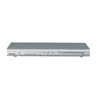
DVD PLAYER
Chassis : Trino
DVD-P241
SERVICE
If you want to know additional information which is not included on this Service Manual, please refer to the
DVD-P241 Training Manual (AK82-00419A).
DVD PLAYER
STANDBY/ON
EZ VIEW
LOADING
Manual
CONTENTS
Advertisement
Chapters
Table of Contents

Related Manuals for Samsung DVD-P241


Summary of Contents for Samsung DVD-P241
-
Page 1: Table Of Contents
6. Schematic Diagrams STANDBY/ON EZ VIEW LOADING © Samsung Electronics Co., Ltd. DEC. 2003 This Service Manual is a property of Samsung Electronics Co.,Ltd. Printed in Korea Any unauthorized use of Manual can be punished under applicable international and/or domestic law. AK82-00418A... -
Page 2: Precautions
Metal Part cal return path to the chassis. Any current measured must not exceed 0.5mA. Reverse the instrument power cord plug in the out- ohmmeter let and repeat the test. See Fig. 1-1. Fig. 1-2 Insulation Resistance Test Samsung Electronics... - Page 3 (5) antenna wiring. Always inspect in all areas tinuously and new instructions are issued whenev- for pinched, out-of-place, or frayed wiring, Do not er appropriate. change spacing between a component and the printed-circuit board. Check the AC power cord for damage. Samsung Electronics...
-
Page 4: Servicing Precautions
Components identi- fied by shading, by( ) or by ( ) in the circuit dia- gram are important for safety or for the characteris- tics of the unit. Always replace them with the exact replacement components. Samsung Electronics... - Page 5 (6) Do not remove a replacement ESD device from its protective package until immediately before your are ready to install it.(Most replacement ESD devices are packaged with leads electrically short- ed together by conductive foam, aluminum foil or comparable conductive materials). Samsung Electronics...
- Page 6 ◆ Be sure to put on a wrist strap grounded to the sheet. ◆ Be sure to lay a conductive sheet made of copper etc. Which is grounded to the table. Samsung Electronics...
- Page 7 3) Make solder land 2 points short on Pick-up. (See Fig. 1-4) 4) Disassemble the Pick-up. Note : If the assembly and disassembly are not done in correct sequence, the Pick-up may be damaged. SOLDER LAND 2 POINTS SHORT PICK-UP ASS'Y Fig. 1-4 Samsung Electronics...
-
Page 8: Alignment And Adjustment
2. Alignment and Adjustment 2-1 Location of Test Point Pin 29 of RIC1 Fig. 2-1 Location of Test Point Samsung Electronics... -
Page 9: Skew Adjustment
Test Point Adjustment Location TDV-533 “Pin 29 of RIC1” Screw A / B Chapter 14 Flat Waveform (Main PCB - Component Side) Ass’y Deck - Top Side (See Fig. 2-1) (See Fig. 2-2) Fig. 2-2 Ass’y Deck (Top Side) Samsung Electronics... - Page 10 If you cannot obtain a Flat waveform, then the unit is defective. Note : The Deck must be in a horizontal position. Use both “A” and “B” screws to adjust. Typical Waveform before Adjustment Waveform after Correct Adjustment Fig. 2-3 Envelope Waveform Samsung Electronics...
- Page 11 3-2 Deck Assembly - - - - - - - - - - - - - - - - - - - - - - - - - - - - - - - - - - - - - - - - - - - Samsung Electronics...
-
Page 12: Exploded Views And Parts List
Exploded Views and Parts List 3-1 Cabinet Assembly P025 W001 W005 W005 C015 P001 A001 C001 C002 Samsung Electronics... - Page 13 Parts No. Description ; Specification Remark A001 AK59-00011K REMOCON-ASSY;DVD-P240/XAA,XAA,-,-,36,-,- C001 AK97-00660B ASSY CABINET-FRONT;HIPS 94 V2,DVD-P240/X C002 AK64-00503B DOOR-TRAY;DVD-P240/XAA,TSEC,ABS 94HB,T2. C015 AK64-00500C CABINET-TOP;DVD-P142/XEL,SECC,T0.5,W429. P001 AK92-00339A ASSY PCB-MAIN;DVD-P241,MAIN ASSY P025 AC39-10200N CBF POWER CORD;EP2,SPT-2,AWG#18,1.8MT,WA W001 6003-000275 SCREW-TAPTITE;BH,+,B,M3,L10,BLK ,SWCH101 W005 6003-000117 SCREW-TAPTITE;BH,+,B,M3,L6,ZPC(YEL),SWRC Samsung Electronics...
-
Page 14: Deck Assembly
Exploded Views and Parts List 3-2 Deck Assembly H212 H102 H205 H900 H204 H202 H903 H903 H210 H241 H211 H207 H206 H206 H904 H904 H203 H209 H107 H105 H106 H903 H103 H108 H104 H109 Samsung Electronics... - Page 15 AK61-00032A HOLDER-CAM SKEW;DP-9,POM,-,-,-,BLACK,- H207 AK31-00014A MOTOR SPINDLE;DP-15,3000RPM,-,-,-,- H209 AK64-00491A CHASSIS SUB;DP-15,POM,-,-,-,-,- H210 AK31-00005A MOTOR-FEED ASSY;-,DP-9,-,-,-,-,-,-,-,-,- H211 AK97-00638A ASSY-PICK UP;-,SOH-DT2,TRINO ASSY PICK U H212 AK61-00253A HOLDER-CHUCK;DP-15,POM,-,-,-,-,- H241 AK41-00156A FFC-P U;DP-15,-,FFC,24,T0.3,LEFT H900 6003-001157 SCREW-TAPTITE;PWH,+,B,M2,L6,ZPC(YEL),SWR H903 6001-001370 SCREW-MACHINE;CH,+,M1.7,L3.0,ZPC(YEL),SW H904 6002-001086 SCREW-TAPPING;PH,+,B,M1.7,L5.0,ZPC(YEL), Samsung Electronics...
-
Page 16: Electrical Parts List
AR48 2007-000092 R-CHIP;15Kohm,5%,1/10W,TP,1608 FR25 2007-000086 R-CHIP;5.6Kohm,5%,1/10W,TP,1608 AR49 2007-000097 R-CHIP;47Kohm,5%,1/10W,TP,1608 FR26 2007-000094 R-CHIP;22Kohm,5%,1/10W,TP,1608 AR50 2007-000097 R-CHIP;47Kohm,5%,1/10W,TP,1608 FR28 2007-007277 R-CHIP;392ohm,1%,1/10W,TP,1608 AR52 2007-000078 R-CHIP;1Kohm,5%,1/10W,TP,1608 2007-000100 R-CHIP;68Kohm,5%,1/10W,TP,1608 AR54 2007-000102 R-CHIP;100Kohm,5%,1/10W,TP,1608 FR30 2007-000070 R-CHIP;0ohm,5%,1/10W,TP,1608 This Document can not be used without Samsung’s authorization. Samsung Electronics... - Page 17 3711-000178 CONNECTOR-HEADER;1WALL,2P,1R,3.96mm,STRA PRS33 2007-000259 R-CHIP;1.6Kohm,5%,1/10W,TP,1608 PCR13 2301-000180 C-FILM,LEAD-PEF;18nF,0.05,100V,TP,7.2x4. PRS34 2007-000491 R-CHIP;2.2KOHM,1%,1/10W,DA,TP,1608 PCR14 2301-000417 C-FILM,LEAD-PEF;24nF,5%,50V,TP,6.5x10.5x PRS52 2001-000325 R-CARBON;120OHM,5%,1/8W,AA,TP,1.8X3.2MM PCR15 2301-000423 C-FILM,LEAD-PEF;3.3nF,5%,100V,TP,7x10x4. PRS55 2001-000062 R-CARBON;470OHM,5%,1/4W,AA,TP,2.4X6.4MM PCS32 2301-000129 C-FILM,LEAD-PEF;100nF,5%,50V,TP,10X9X4.3 PRS56 2001-000449 R-CARBON;2.2KOHM,5%,1/8W,AA,TP,1.8X3.2M This Document can not be used without Samsung’s authorization. Samsung Electronics...
- Page 18 R-CHIP;10Kohm,1%,1/10W,TP,1608 ZC41 2203-005148 C-CER,CHIP;100nF,10%,16V,X7R,TP,1608,- 2007-000078 R-CHIP;1Kohm,5%,1/10W,TP,1608 ZC42 2203-005148 C-CER,CHIP;100nF,10%,16V,X7R,TP,1608,- 2007-000078 R-CHIP;1Kohm,5%,1/10W,TP,1608 ZC43 2203-005148 C-CER,CHIP;100nF,10%,16V,X7R,TP,1608,- 2007-000312 R-CHIP;10ohm,5%,1/4W,TP,3216 ZC44 2203-005148 C-CER,CHIP;100nF,10%,16V,X7R,TP,1608,- 2007-000084 R-CHIP;4.7Kohm,5%,1/10W,TP,1608 ZC45 2203-005148 C-CER,CHIP;100nF,10%,16V,X7R,TP,1608,- 2007-000381 R-CHIP;13Kohm,5%,1/10W,TP,1608 ZC46 2203-005148 C-CER,CHIP;100nF,10%,16V,X7R,TP,1608,- This Document can not be used without Samsung’s authorization. Samsung Electronics...
- Page 19 ZR45 2007-000084 R-CHIP;4.7Kohm,5%,1/10W,TP,1608 ZR46 2007-000074 R-CHIP;100ohm,5%,1/10W,TP,1608 ZR47 2007-000084 R-CHIP;4.7Kohm,5%,1/10W,TP,1608 ZR48 2007-000084 R-CHIP;4.7Kohm,5%,1/10W,TP,1608 ZR49 2007-000084 R-CHIP;4.7Kohm,5%,1/10W,TP,1608 ZR50 2007-000084 R-CHIP;4.7Kohm,5%,1/10W,TP,1608 ZR54 2007-000084 R-CHIP;4.7Kohm,5%,1/10W,TP,1608 2007-001101 R-CHIP;62ohm,5%,1/10W,TP,1608 2007-000070 R-CHIP;0ohm,5%,1/10W,TP,1608 2007-001164 R-CHIP;75ohm,1%,1/10W,TP,1608 2801-003554 CRYSTAL-UNIT;27MHz,10ppm,28-AAM,12pF,40o This Document can not be used without Samsung’s authorization. Samsung Electronics...
-
Page 20: Block Diagram
Actuator & Motor Driver Decoder AC3 & MPEG 5.1 VIC1 Compo CVBS (LA73054) Yout Y/B/Pb Cout Video 6dB AMP Encoder Post (4DAC) R/Pr C/R/Pr Filter 6dB AMP B/Pb Comp/G/Y Samsung Electronics This Document can not be used without Samsung’s authorization. -
Page 21: Schematic Diagrams
6-6 Key - - - - - - - - - - - - - - - - - - - - - - - - - - - - - - - - - - - - - - - - - - - - - - - - - - Main PCB (Component Side) Samsung Electronics This Document can not be used without Samsung’s authorization. -
Page 22: Power
Schematic Diagrams 6-1 Power This Document can not be used without Samsung’s authorization. Samsung Electronics... -
Page 23: Av-Decoder/Main-Micom
Schematic Diagrams 6-2 AV-Decoder/Main-Micom Samsung Electronics This Document can not be used without Samsung’s authorization. -
Page 24: Servo
Schematic Diagrams 6-3 Servo This Document can not be used without Samsung’s authorization. Samsung Electronics... -
Page 25: Video
Schematic Diagrams 6-4 Video Samsung Electronics This Document can not be used without Samsung’s authorization. -
Page 26: Audio
Schematic Diagrams 6-5 Audio This Document can not be used without Samsung’s authorization. Samsung Electronics... -
Page 27: Key
Schematic Diagrams 6-6 Key Samsung Electronics This Document can not be used without Samsung’s authorization.
Need help?
Do you have a question about the DVD-P241 and is the answer not in the manual?
Questions and answers