Table of Contents
Advertisement
Quick Links
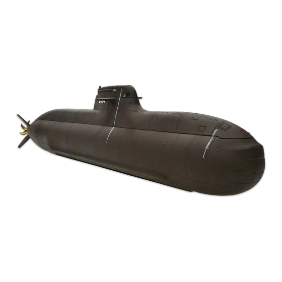
Submarine Class
212
Assembly & Operation
Please read the following building instructions and safety warnings carefully
BEFORE commencing with assembly of kit and installation of technical equipment.
Please also refer to the safety guidelines on page 38.
WARNING!
During the charging period all batteries must be removed from the hull. NEVER
charge the batteries within the hull as most regular lead batteries gas while being
charged. Insufficient air circulation during the charging period may lead to a
serious EXPLOSION!
Please adhere to your country's safety guidelines during construction and operati-
on of this item.
We are not liable for any personal injury or damage of any kind resulting with the
assembly and/or use of our products as we are neither able to delegate nor verify
the assembly and/or use of these items.
We reserve the right to alter technical specifications.
Copyright ©2011 ALEXANDER ENGEL KG Bi1599
www.modelsubmarines.com
Item No. 1599
Manual
Parts List
All rights reserved.
v1-11
Advertisement
Table of Contents

Subscribe to Our Youtube Channel
Summary of Contents for ALEXANDER ENGEL 212
-
Page 1: Parts List
We reserve the right to alter technical specifications. Copyright ©2011 ALEXANDER ENGEL KG Bi1599 All rights reserved. v1-11... -
Page 2: Table Of Contents
Item No. 1599 Table of Contents Introduction ...............3 Part A 1. -
Page 3: Introduction
Item No. 1599 The 212 class has become increasingly popular since its release, this is true for the original boat as well as the miniaturised model. This new ENGEL submarine offers besides radial parting with bayonet lock ring and Tech Rack© very compact dimensions and easy handling. - Page 4 Item No. 1599 As soon as the submarine re-emerges to the water surface the pressure within the model decreases (as the Piston Tank empties), whereby periscopes, radar, snorkel and antennas retract. The mechanism also serves as safety indicator. Should the model suffer a leakage during its dive, the over-pressure within the boat will decrease forcing the conning tower mechanism to extract.
-
Page 5: Part A
Before you start with the assembly we highly recommend to build a simple stand for your model. A professionally made boat stand for the 212 is also available as an option (item-no. 1599-Z). Cover the stand with cling film or cloth. -
Page 6: Installation Of Cables And Tubes
Item No. 1599 1.5 Push Pressure Switch in carrier T2 and check for good fit. 1.6 Accessibility of screws in Piston Tank bulk head is given by three corresponding holes in bow bulk head (see picture). 2. Installation of Cables and Tubes 2.1 Insert three brass tubes, outer dia. -
Page 7: Mounting And Connection Of Cts To Piston Tank
Yellow to micro switch S2, tag 1 and "+" pole of motor. Violet to micro switch S1, tag 1 and counter-pole of motor. 3.3 Install wires accurately around spindle and motor. 3.4 Coat contact tags of micro switches with contact spray in order to prevent oxidation. Copyright ©2011 ALEXANDER ENGEL KG... - Page 8 Item No. 1599 3.5 Before sliding the CTS onto the micro switches, slightly press contact tags 2 and 4 of each Piston Tank together so that the tags lie parallel to one another. This will facilitate fitting of the unit. CAREFULLY widen the blade receptacles (pre-soldered to the CTS' back side) with a small screwdriver.
-
Page 9: Centre Section
4.5 Prior to final assembly purpose-made power socket must be installed into opening of the Centre Section's right-hand side part (seen from aft to bow). This building sequence is described in chapter 9. Bore for fastening Pitch Controller drill bit Copyright ©2011 ALEXANDER ENGEL KG... - Page 10 Item No. 1599 Bi1599 v1-11...
-
Page 11: Servo Block
JST connector (red) should also be plugged onto the two pin row for automatic pitch reverse on the DLx. Pass the two wire leads through both servo bulk heads beneath the mounting plate for the electronic speed controller (ESC). Do not cut wire, yet. Copyright ©2011 ALEXANDER ENGEL KG... - Page 12 Item No. 1599 Bi1599 v1-11...
-
Page 13: Main Drive Battery And Arrangement Of Wire Leads
Centre Section. Determine cable length required, measured from CT- 3.5 connector through cable guiding tube S6, ending just below switch unit CTS (approx. 350 mm). Cut accordingly. Copyright ©2011 ALEXANDER ENGEL KG... -
Page 14: Receiver Battery And Arrangement Of Wire Leads
Item No. 1599 6.11 Strip insulation of wires by about 3 mm and tin-plate. Solder contacts with housing in accordance to CT-3.5 connec- tor formerly fitted to main battery packs. Solder 3.5 mm socket and plug (supplied without housing) to wire ends below CTS. These connectors are insulated with heat shrink tube 4 x 8 mm. -
Page 15: Installation Of Speed Controller
(blue/white) between ESC and motor. 8.9 ESC can be fixed with double-sided adhesive tape onto its mounting plate. Only use high-quality tape as adhesive strength of cheap tape will soon deteriorate, especially in a moist envi- ronment. Copyright ©2011 ALEXANDER ENGEL KG... -
Page 16: Power Socket
Item No. 1599 9. Power Socket Assignment of socket pins (example) Applies to optional cable and connector set, item no. 1599-99. 9.1 This socket is located within the Central Section, fitted in a receiver battery frame to an opening in the side of that section. The socket feeds power from the main drive and receiver battery to the model's electric and electronic components. -
Page 17: Charge Lead
12.2 Plug wire leads connected to power socket into extensions below CTS. Ensure that all connections are properly insu- lated. 12.3 The Tech Rack can be put aside until merged with hull. Bore for fastening Pitch Controller Copyright ©2011 ALEXANDER ENGEL KG... -
Page 18: Installation Of Steering Gear
Item No. 1599 13. Installation of Steering Gear 13.1 The four attachment parts for the control planes are already factory-glued to the hull. 13.2 There are two pairs of guiding tubes. One pair measures 23.4 mm (L3), the other pair 17.4 mm (L5). Each of these are mounted oppositely as shown on the picture below. -
Page 19: Main Drive
14.6 Apply a small amount of grease on O-ring A9 and push O-ring into centre bore of main bulk head R12. 14.7 Slide motor mount A2 into main bulk head R12 and fasten with four nuts Y4. Copyright ©2011 ALEXANDER ENGEL KG... - Page 20 Item No. 1599 Bi1599 v1-11...
-
Page 21: Main Bulk Head
15.6 Mix a small amount ("hazelnut") of 1-Hour Epoxy with Micro Balloons and fill the joint between hull walling and bulk head from inside of hull. Leave to set for at least four hours. breather tube (pre-fitted) Copyright ©2011 ALEXANDER ENGEL KG... - Page 22 Item No. 1599 Bi1599 v1-11...
-
Page 23: Push Rods And Linkages
16.5 Glue remaining length of L11 into clevis L9. Fit collar L12 with screw L13 and push collar onto L10. Snap-in clevis into each yoke. 16.6 Push control rod S1 into L10 and fasten with L12. Copyright ©2011 ALEXANDER ENGEL KG... - Page 24 Item No. 1599 Bi1599 v1-11...
- Page 25 Item No. 1599 Copyright ©2011 ALEXANDER ENGEL KG...
-
Page 26: Bayonet Lock Ring
Item No. 1599 17. Bayonet Lock Ring 17.1 This building sequence will require a fair amount of glue. Therefore, ensure good ventilation of your workshop. Wear protective gloves and glasses. Moreover, refer to the safety guidelines according to manufacturer of adhesive used. We recommend 1-Hour Epoxy (item no. - Page 27 Item No. 1599 Copyright ©2011 ALEXANDER ENGEL KG...
-
Page 28: Receiver, Speed Controller, Servos And Pitch Conroller
Item No. 1599 18. Receiver, Speed Controller, Servos and Pitch Contoller 18.1 Attach receiver (Rx) on top cover of Centre Section, either with double-sided tape or Velcro® (hook-and-loop tape). Insert antenna wire into guiding tube S9 (made of white, flexible plastic). A piece of thin steel or brass wire or any stiff mate- rial with a maximum diameter and a length of more than 1 m will prove helpful. -
Page 29: Initial Launch Of Cts With Piston Tank
With battery voltage already lower than threshold value when system is powered up will lead to deac- tivation of this safety device. This mode is indicated by the red LED flashing. However, the CTS will allow the tank to fill, thus, the boat to submerge despite low voltage. Copyright ©2011 ALEXANDER ENGEL KG... -
Page 30: Joining Tech Rack And Hull
Item No. 1599 20. Joining Tech Rack and Hull The following building sequence demand a fair amount of patience as well as diligence. Several components must now be connected almost simultaneously. These include ESC to motor, control rods to servos and, last but not least, two tubings (already fitted to outboard nozzles in main bulk head) to brass tubes running through the Tech Rack. -
Page 31: Hull Ridge, Bilge And Side Keels
1-Hour Epoxy. Alternatively, a fast set- ting epoxy (i.e. 4-Minute Speed Epoxy, item no. 9504) can be File notch into back used. edge of aft ridge Small engravings on side keels face upwards Copyright ©2011 ALEXANDER ENGEL KG... - Page 32 Item No. 1599 Bi1599 v1-11...
-
Page 33: Main Ballast
However, glue penetrating the bayonet lock ring must be removed IMMEDIATELY with a damp cloth. 23.5 Leave to set for 12-24 hours. SEEN FROM AFT TO BOW Ballast RIGHT Ballast LEFT HULL CENTRE LINE Copyright ©2011 ALEXANDER ENGEL KG... -
Page 34: Revision Opening And Cover
Item No. 1599 24. Revision Opening and Cover Cover R13 is held within the revision opening by magnets. One magnet R16 is glued to cover R13, the second magnet R16 into fixture R15. After assembly, magnets will sit slightly offset to one another whereby cover is held safely in place. -
Page 35: Conning Tower Mechanism (Optional)
- do not use a pump! Only a slight overpressure must be generated within the hull, so do not exaggerate. Close breather. Switch Piston Tank to fill. The sealing ring will now be released by this increase in pressure. Switch Piston Tank to empty and release remaining overpressure by opening breather. chamfer chamfer Copyright ©2011 ALEXANDER ENGEL KG... -
Page 36: Leak Test
Item No. 1599 Part C 27. Leak Test It is important to stick to the following sequence. Checking for leaks is essential. Before trimming can be commenced it must be ensured that the model is 100% pressure proof. If Conning Tower Mechanism is used, leave connected to hull but detach hull ridge. -
Page 37: Paintwork
Just make sure that seal is not damaged by any circumstance! A small amount of TITAN grease (item no. 9707) applied to the aft bayonet ring will not only keep O-ring X4 in nice and sleek but will also improve interlocking of rings. Copyright ©2011 ALEXANDER ENGEL KG... -
Page 38: Safety Guidelines
Item No. 1599 ENGEL Piston Tanks are superior to other designs als superior in terms of resilience to pollution. Even slush will not cause a malfunction of the tank as all material drawn into the tank will eventually be discharged. Maintenance of the Piston Tank only requires lubrication of the middle cog wheel's retaining bolt with white oil (as used for fire arms or sewing machines). - Page 39 Part Listing Type 212 Part No. Qty. Description Dimension/Material Pack Resin Cast Parts hull front part Resin hull aft part Resin bayonet lock ring outer Resin bayonet lock ring inner Resin hull ridge front Resin hull ridge aft Resin...
- Page 40 Part Listing Type 212 Part No. Qty. Description Dimension/Material Pack coupler 10x22-brass propeller shaft sealing ring 4-11-6, NBR 4.1.1 propeller shaft bushing 10x10x10-PVC 4.1.1 o-ring 16x2.5 4.1.1 Tubings and Gaskets tubing 6 x1.5 x 600-PVC tubing 2x 0.5 x 350-silicone bellow 1.5-5-32, NBR...
Need help?
Do you have a question about the 212 and is the answer not in the manual?
Questions and answers