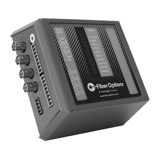
Summary of Contents for GE Interlogix S734DV
- Page 1 GE Interlogix Fiber Options S734DV & S7734DV FIBER-OPTIC SYSTEM FOUR-CHANNEL VIDEO AND MULTI-PROTOCOL DATA...
- Page 2 Federal Communications Commission and Industry Canada Radio Frequency Interference Statements This equipment generates, uses, and can radiate radio frequency energy and, if not installed and used properly in strict accordance with the instructions contained herein, may cause interference to radio communication. It has been tested and found to comply with the limits for Class A computing devices in accordance with the spec- ifications found in Subpart J of Part 15 of FCC rules, which are designed to provide reasonable protection against such interference...
- Page 3 3.5-mm) screws. Once the plate is securely attached to a flat rack card. Units should be installed in dry locations protected surface, the S734DV is mounted on the plate and can be easily from extremes of temperature and humidity. removed. Refer to Figure 1 for details.
-
Page 4: Module Setup
FIGURE 1: MOUNTING PLATE FIGURE 2: OPTIONAL SECURITY CLIP PLACEMENT Mounting plate Security clip attaches to selected attaches to the surface with six rear of the suitable screws. module via Standalone mod- any of these ules are mounted four screws. by sliding it onto the DO NOT plate’s hooks until... - Page 5 FIGURE 3: DATA SELECT SWITCH SETTINGS Setting Mode Setting Mode Disable (factory preset) RS-485 2-wire 2V RS-232 RS-485 4-wire standard RS-232 + handshake RS-485 4-wire 1V RS-485 4-wire 2V RS-422 2-wire Reserved Manchester/Biphase Reserved RS-485 2-wire standard Reserved RS-485 2-wire 1V Test Mode Tx FIGURE 4: RACK-MOUNT RECEIVER - SWITCH AND JUMPER LOCATION VIDEO OUT 1...
- Page 6 FIGURE 5: RACK-MOUNT TRANSMITTER - SWITCH AND JUMPER LOCATIONS VIDEO IN 1 VIDEO CARD VIDEO IN 2 VIDEO IN 3 VIDEO IN 4 OPTICAL CONNECTOR NTSC DISABLE RELAY/CONTACT 1/2 CONNECTOR DATA CARD RELAY/CONTACT 3/4 CONNECTOR DATA CONNECTOR DATA SELECT SWITCH SW1 ON ALARM Alarm Jumper Rack cards are supplied with an alarm function that activates if...
-
Page 7: Data Translation
Disabling the test pattern generator causes no signal output Video Format/Test Pattern Generator during the failure conditions or when using the Test Mode The S734DV links support both NTSC and PAL video stan- described on page 9. dards without adjustment. The S734DVT transmitter and... -
Page 8: Data Equipment
TABLE 1: DATA TRANSLATIONS Translation Switch Switch Comment Setting Setting RS-232, 3 wire Signal level conversion. RS-232, 3 wire Signal level conversion. RS-422 Single Ended to Differential Conversion. RS-422 Differential to Single Ended Conversion. RS-232, 3 wire RS-422 Single Ended to Differential Conversion. RS-422 RS-232, 3 wire Differential to Single Ended Conversion. - Page 9 TABLE 2: TABLE3: TABLE 4: RS-232 Interface RS-232 with Handshaking Interface TTL Interface Mode Switch SW1: Position 1 Mode Switch SW1: Position 2 Mode Switch SW1: Position 3 Pin No. Function Pin No. Function Pin No. Function Ground Ground Ground RTS/CTS IN TTL IN RS-232 IN...
-
Page 10: Power Connections
BNC connectors on the S734DVT transmitter using ter- SMARTS DIAGNOSTICS minated coaxial cable. See Figures 6 and 8. The S734DV has built in Status Monitoring And Reliability 2. Connect the monitoring equipment to the output BNC con- Test System (SMARTS ) diagnostic capabilities. This... -
Page 11: Monitor Display
When the test is completed, run the test again in the opposite 1. On one of the S734DV units, set the rotary DATA SELECT direction by changing DATA SELECT switch positions and switch to position F (TEST MODE). At this end only, wire the connectors. - Page 12 In a standard RS-485 system, when a driver on a properly ter- The DATA IN LED indicates the state of the data being input to the S734DV over copper. A green DATA IN LED indicates minated bus goes into tri-state (inactive), the voltage between a logic HIGH is present on the copper inputs.
-
Page 13: Shipping And Packaging
OPERATION If any equipment must be returned to Fiber Options for repair S734DV links operate automatically once installed. Refer to or replacement, you must obtain authorization from our Return TEST MODE on page 9 for information on how to execute the Authorization department before shipping. - Page 14 INSTRUCTION MANUAL . . . light years ahead ™ TABLE 12: LED DIAGNOSTIC INDICATORS LED Name Color Indicates/Corrective Action Green Sufficient optical power received. No action required. LEVEL/ Insufficient optical power received. Verify fiber connected & within optical budget, LOSS receiver power on.


Need help?
Do you have a question about the S734DV and is the answer not in the manual?
Questions and answers