
Related Manuals for ABB ACS55


Summary of Contents for ABB ACS55
- Page 1 User's Guide ACS55 for type ACS55 AC Drives from 0.18 to 2.2 kW English Dansk Deutsch Español Suomi Français Italiano Nederlands NL Português Русский Svenska 中文 한국어...
- Page 2 한국어 ................249 3AFE68929300 Rev B EN, DA, DE, ES, FI, FR, IT, NL, PT, RU, SV, CN, KR Effective: 25.02.2008 © 2008 ABB Oy. All Rights reserved.
- Page 3 User's Guide for type ACS55 AC Drives from 0.18 to 2.2 kW English...
- Page 4 Product and service inquiries Address any inquiries about the product to your local ABB representative, quoting the type code and serial number of the unit in question. A listing of ABB sales, support and service contacts can be found by navigating to www.abb.com/drives...
-
Page 5: Safety Instructions
Safety instructions Altering the DIP switches will affect the function and performance of ACS55. Check that the changes will not cause any risk to Read the following instructions carefully before proceeding with the persons or property. installation. About this manual Warning! Dangerous voltage! Only a competent electrician may install ACS55. -
Page 6: Overview Of The Unit
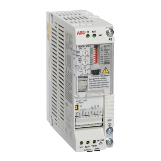
Overview of the unit ACS55 drive controls the speed of a 3-phase AC induction motor. Protective earth (PE), page Input terminals, page Power on LED, page DIP switches, page Fault LED, page Control potentiometers, page DriveConfig kit interface, page Relay output terminals, page... -
Page 7: Installation And Start-Up Steps
Action Check the delivery. Ensure that the installation environment is suitable for ACS55. Mount the unit. Check applicability of the standard settings: Motor nominal frequency is 50 Hz; load is a pump or a fan; maximum output frequency is 50 Hz. If the standard settings are not suitable, adjust the DIP switches. -
Page 8: Environmental Limits
Not allowed Not allowed 1) When operating the drive in subzero temperatures, keep the input power connected. Install the drive inside an enclosure. Ensure that heat generated by the drive will be properly dissipated. Degree of protection of ACS55 is IP20. - Page 9 Dimensions Frame Frame Frame Frame (in.) (in.) (in.) (in.) (2.09) (2.83) (2.91) (2.91) 67.5 (1.77) (2.66) (2.76) (2.76) (5.04) (5.04) (6.26) (6.26) 67.5 67.5 (2.66) (2.66) (3.03) (3.03) (1.57) (1.57) (1.57) (1.57) (7.20) (7.20) (9.06) (6.14) (6.14) (7.17) (8.43) (6.69) (6.69) (7.64) (8.90)
- Page 10 Warning! The unit will warm up to high temperature during normal operation. Ensure sufficient cooling air flow in all conditions: - Always install ACS55 so that cooling fans are vertical. - Leave sufficient space around frame A and B units. Frame C and D units are fan cooled, so they can be installed side by side without extra space between them.
- Page 11 Attaching and detaching the wall mounting clip The unit can be mounted either with the wide or the narrow side against the wall. Install the mounting clip on the desired side. See instructions below for frames A and B. Detach the mounting clip of frames C and D by pulling downward and attach it by pushing upward.
-
Page 12: Dip Switches
DIP switches DIP switches are used to adapt ACS55 to the motor and the application. Warning! The DIP switch is at a dangerous voltage (200 V). Turn off power and wait for 5 minutes before adjusting the switches. Keep the protective cover closed when ACS55 is powered. - Page 13 RUN = Running. Contact is closed while running. Activates a living zero supervision for the analogue input. 4 mA (2 V) = ACS55 trips on a fault if the value drops OFFSET below the limit.
-
Page 14: Control Potentiometers
Calculate MOTOR I NOM with the equation below or pick a value from the MOTOR I NOM selection chart below. ACS55 estimates the temperature of the motor based on the measured output current and the defined motor nominal current. The drive trips if the estimated temperature implies motor overheating. -
Page 15: Connecting Power Supply And Motor
30°C (86°F). See also Additional cabling and EMC instructions on page 19. Earth leakage current of the ACS55 can exceed 3.5 mA AC / 10 mA DC. According to EN50178, ACS55 may only be used in permanent installation. Input fuse... -
Page 16: Connecting Control Wires
Connecting control wires Control terminals Use multi-strand 0.5...1.5 mm wire (AWG22 - AWG16). Internal (1) or external (2) power supply can be used for the digital Name Description inputs. Analogue control voltage is 0…10 VDC as default. (The AI jumper must be in voltage ("U") position). Common for digital or analogue inputs Common for digital or analogue input Analogue input: Speed (frequency) reference. -
Page 17: Additional Cabling And Emc Instructions
Additional cabling and EMC instructions Follow these instructions for trouble free operation and to ensure compatibility with the European EMC directive. Motor cable The motor cable must be a symmetrical three conductor cable with a concentric PE conductor or a four conductor cable with a concentric shield. -
Page 18: Speed Controlling
Speed controlling The analogue input gives the speed (frequency) reference for ACS55. The correspondence between the analogue input and the reference depends on the settings of the DIP switches as shown below. Output frequency follows the reference changes as defined by the ACC/DEC potentiometer. -
Page 19: Status Indications And Fault Tracing
Motor overload (I t overload): 1) Check the load, and verify that the motor size is suitable for ACS55. 2) Verify that setting of MOTOR I NOM potentiometer is correct. Output short circuit: Switch off the power and check the motor Inverter overload or excessive internal temperature: 1) Load windings and motor cable. -
Page 20: Technical Data
Technical data 230 V 115 V Built-in EMC, ACS55-01E- 01A4-2 02A2-2 04A3-2 07A6-2 09A8-2 01A4-1 02A2-1 No EMC, ACS55-01N- 01A4-2 02A2-2 04A3-2 07A6-2 09A8-2 01A4-1 02A2-1 Motor continuous output power 0.18 0.37 0.75 0.18 0.37 Frame size (no EMC) Frame size (EMC) - Page 21 Distribution networks isolated from earth To comply with European EMC regulations, the motor cable length Drives with built-in EMC filter, or ACS55-IFAB-01 external input has to be limited as specified in the table below. The shorter the filter must not be used in a floating network or in a high impedance motor cable, the lower the noise emissions to the supply line and earthed industrial distribution network.
- Page 22 Approvals UL, cUL: The ACS55 is suitable for use on a circuit capable of delivering not more than 65 kA rms symmetrical amperes, 230 volts maximum, when protected by CC or T class fuses. The ACS55 complies with the requirements of the European C-Tick: •...
- Page 23 Cheshire WA4 4BT UNITED KINGDOM Telephone +44 1925 741111 +44 1925 741212 ABB Oy ABB Inc. ABB Beijing Drive Systems Co. AC Drives Automation Technologies Ltd. P.O. Box 184 Drives & Motors No. 1, Block D, A-10 Jiuxianqiao FI-00381 HELSINKI...
Need help?
Do you have a question about the ACS55 and is the answer not in the manual?
Questions and answers