Table of Contents
Advertisement
Quick Links
Advertisement
Table of Contents

Summary of Contents for QUANTUM X CX27
- Page 1 Operating Manual CX27 Gateway I2720-2.0 en...
-
Page 3: Table Of Contents
..............CX27-object specifications . - Page 4 10 Abbreviations ............11 Support .
-
Page 5: Safety Instructions
Safety instructions Safety instructions Appropriate use The module and the connected transducers may be used for measurement and directly related control tasks only. Any other use is not appropriate. To ensure safe operation, the module may only be used as specified in the operating manual. - Page 6 Safety instructions Conditions on site For modules with degree of protection IP20: − Protect the modules from humidity or effects of the weather such as rain, snow, etc. − The permissible relative humidity at 31°C is 80% (non-condensing); linear reduction down to 50%, at 40°C.
- Page 7 Safety instructions Conversions and modifications The module must not be modified from the design or safety engineering point of view except with our express agreement. Any modification shall exclude all liability on our part for any resultant damage. In particular, any repair or soldering work on motherboards (replacement of components) is prohibited.
- Page 8 Safety instructions In this manual, the following symbols are used to point out residual dangers: DANGER Symbol: Meaning: Maximum danger level Warns of an imminently dangerous situation in which failure to comply with safety requirements will result in death or serious bodily injury. WARNING Symbol: Meaning: Dangerous situation...
- Page 9 Safety instructions Symbols pointing out notes on use and waste disposal as well as useful information: NOTE Symbol: Points out that important information about the product or its handling is being given. Symbol: Meaning: CE mark The CE mark enables the manufacturer to guarantee that the product complies with the requirements of the relevant EC directives (the declaration of conformity is available at http://www.hbm.com/hbmdoc).
-
Page 10: Documentation
Documentation Purpose of this operating manual This operating manual gives you information about the CX27 EtherCAT Gateway to the measurement modules of the QuantumX DAQ family. It should support you in integrating the QuantumX family into your real-time automation jobs. -
Page 11: General Information
The CX27 QuantumX module is a so-called gateway. A gateway allows networks based on totally different protocols to communicate with each other. The main task of the Ethernet/EtherCAT CX27 Gateway is to receive and forward the data of the modules connected via FireWire. - Page 12 Fig. 2.2: CX27 connection via the BPX001 backplane The CX27 Gateway has two Ethernet interfaces and one EtherCAT interface (IN/OUT) for a network connection. The Ethernet interfaces at the front and back of the module are equivalent, and are implemented as RJ45 sockets.
- Page 13 10 V − 30 V DC MX... CX27 X102 X101 X102 X101 Alternative Ethernet connection max. 1.5 A at the front X102 FireWire connection X101 1-Kab269-2 2 m connection cable Ethernet connection Fig. 2.3: Example: Ethernet connection to a PC/laptop via CX27 QuantumX...
- Page 14 The RJ45 connecting sockets at the front, X8 and X9, are designed for connection to the EtherCAT fieldbus with real-time capability (Ethernet for Controller and Automation Technology). 10 V − 30 V DC MX... MX... CX27 (slave) FireWire EtherCAT connection Master Further slaves Fig. 2.4: Example: QuantumX-EtherCAT connection via CX27 QuantumX...
-
Page 15: Ethercat Connection
You must first configure the relevant module channels for isochronous data transmission with the QuantumX Assistant (”Signals” tab) and via Ethernet TCP/IP: 1. Connect your modules in the deactivated state to the CX27 Gateway via FireWire cable 1-KAB269 (from connection X102 to X101, etc.), or use the active 1-BPX001 backplane for connection. -
Page 16: Configuration With Twincat
• Highlight the inputs address field under the ”Sync Manager” dialog • Activate ”PDO Assignment” and mark amount of PDOs (= QuantumX isochronous signals) • Run EtherCAT Master and check PDO data from CX27 Slave (basic measurement) Select Inputs Check amount... -
Page 17: Configuration With Ethercat Studio
• Right-click on EtherCAT Master in ”Append” dialog, select ”HBM Communication modules −> HBM CX27” • Attach master and accept ”Online Operations” for network scan • Select CX27 Slave and click ”CoE Online” tab • Refresh object dictionary and check identifiers (AI_connector_identification) • Select ”FMMU/SM” tab on CX27 slave •... -
Page 18: Ethercat
MX840 MX ... Fig.5.5: Example: CX27 Gateway to EtherCAT, modules connected via FireWire Principle of operation In contrast to standard Ethernet, the Ethernet Frames from the slaves are processed in passing (IN and OUT sockets). The standard Ethernet Frame sent by the master (as per IEEE 802.3) is not first received, then interpreted and the process data copied at every... -
Page 19: Configuration
Configuration Most of the effort required for implementation is usually taken on by the configuration tool. Clearly defined interfaces have been created to minimize this effort. The configuration tool learns about the device properties from the XML file (Device Description File = DDF). In turn, the configuration tool also generates an XML file containing all the relevant information about the network topology, the process data layout, startup and diagnosis. - Page 20 CANopen uses communication objects with different properties: Service Data Objects (SDO) In the parameter channel, all the CX27 parameters can be read and modified by the SDO service. The required parameter is addressed within an SDO telegram by index and sub-index.
-
Page 21: Synchronization
1200 Hz. Up to 3 Sync Managers can be assigned. The CX27 operates with the ”SYNC 0” pulse. The cycle time can be set up to the 125 µs range. Smaller values cause the loss of real-time data. -
Page 22: Cx27-Object Specifications
CANopen CX27 object specifications Possible SDOs for the Gateway are described in this chapter (name, description, value range, data type, index/sub-index) Index The index gives the position of the object in the object dictionary. The index value specification is hexadecimal. The values for the DS404 device profile are located from address 0x6xxx. - Page 23 CANopen Object index organization Object index (hex) Object index (dec) Object 0000 Not used 0001 − 001F 1 − 31 Static Data Types 0020 − 003F 32 − 63 Complex Data Types 0040 − 005F 64 − 95 Manufacturer Specific Complex Data Types 0060 −...
- Page 24 CANopen SDO Object overview Description Object name Index (hex) Page Sensor Sensor type AI_Sensor_type 6110 Operating mode AI_Operating_mode 6112 ADC sample rate AI_ADC_sample_rate 6114 Sensor manufacturer Al_Sensor_manufacturer 6115 Sensor model Al_Sensor_model 6116 Sensor serial number Al_Sensor_serialnumber 6118 Sensor location Al_Sensor_location 6119 Sensor calibration period Al_Sensor_ calibration_period...
-
Page 25: Detailed Object Description
CANopen Detailed object description Analog input sensor type Object description Index 6110 (hex) 24848 (dec) Note Object name AI_sensor_type Specifies the type of sensor which is connected to the analog input connected to the analog input. Object code Array Data type UINT16 CiA standard Category... - Page 26 CANopen Value Description 4 − 20mA 0 − 20mA 53 − 59 Reserved Frequency 61 − 69 Reserved Strain gage Strain gage full bridge Analog input sensor type Strain gage half bridge Strain gage quarter bridge 74 − 79 Reserved LVDT 81 −...
- Page 27 CANopen Analog input operating mode Object description Index 6112 (hex) 24850 (dec) Note Object name AI_Operating_mode A value other than 0 sets the analog input channel to special operating modes channel to special operating modes. Object code Array Data type UINT8 CiA standard Category...
- Page 28 CANopen So it is useful to indicate the mode of the signal in object 6112h as follows: 10: Signal_S1 11: Signal_S2 20: Signal_positive_peak 21: Signal_negative_peak 22: Signal_peak_to_peak 30: Signal_rms 100: Signal_CAN QuantumX...
- Page 29 CANopen Analog input ADC sample rate Object description Index 6114 (hex) 24852 (dec) Note Object name AI_ADC_sample_rate This value uses the reciprocal conversion rate deployed by the AD converter The value is deployed by the AD converter. The value is Object code Array given in multiples of microseconds.
- Page 30 CANopen Analog input sensor model Object description Index 6116 (hex) 24854 (dec) Note Object name AI_sensor_model This value provides the model of each connected sensor connected sensor. Object code Array Data type Visible string CiA standard Category Optional Value description 0 (hex) 1 (hex) 2 (hex)
- Page 31 CANopen Analog input sensor location Object description Index 6119 (hex) 24857 (dec) Note Object name AI_sensor_location This value provides the ”LocationID” defined in IEEE14514 in IEEE14514. Object code Array Data type UINT16 CiA standard Category Optional Value description 0 (hex) 1 (hex) 2 (hex) C7 (hex)
- Page 32 CANopen Sensor calibration period Object description Index 611B (hex) 24859 (dec) This value provides the recommended time period between transducer calibrations The period between transducer calibrations. The Object name AI sensor calibration period value may be added to the calibration date value may be added to the calibration date to calculate the date for the next calibration.
- Page 33 CANopen Filter type Object description Index 61A0 (hex) 24992 (dec) Object name AI_Filter_type Object code Array Data type UINT8 CiA standard Value description − index Description Filter characteristics selection Access PDO mapping Values No filter Moving average Repeating average pass Bessel characteristic pass pass Bessel and low...
- Page 34 CANopen Status Object description Index 6150 (hex) 24912 (dec) Object name AI_Status Object code Data type CiA standard To be incorporated Data content 0 (LSB) No sensor connected, signal invalid, overload. 1 and 4 Set, if object 611C has value of 3 (TEDS_required) and TEDS is not present or invalid or object 611C has value of 2 (use TEDS if available) and TEDS is invalid.
- Page 35 CANopen Connector signal name Object description Index 61B0 (hex) 25008 (dec) Object name AI_Connector_signalname Object code Data type Character string CiA standard Character string String to describe the meaning of the signal Connector identification Object description Index 61B1 (hex) 25009 (dec) Object name AI_Connector_identification Object code...
- Page 36 CANopen Input scaling 1, field value (electrical input, float format, point 1) Object description Index x120 (hex) 24864 (dec) Note Object name AI_Input_scaling_1_FV This object defines the field value of the first calibration point for the analog input channel calibration point for the analog input channel. Object code Array It is scaled in the physical unit of the field...
- Page 37 CANopen Input scaling 2 field value (physical output, float format, point 2) Object description Index x122 (hex) 24866 (dec) Note Object name Input_scaling_2_FV This object defines the field value of the second calibration point for the analog input second calibration point for the analog input Object code Array channel.
- Page 38 CANopen Scaling factor Object description Index 6126 (hex) 24870 (dec) Note Object name AI_Scaling_Factor This object represents the scaling factor by which the field value needs to be multiplied which the field value needs to be multiplied Object code Array to obtain process values.
- Page 39 CANopen Input PV (characteristic curve output unit) Object description Index x130 (hex) (dec) Note Object name AI_Input_PV This object represents the result of the input scaling block and gives the measured scaling block and gives the measured Object code Array quantity scaled in the physical unit of the quantity scaled in the physical unit of the process values (e.g.
- Page 40 CANopen Physical unit PV (characteristic curve output unit) Object description Index 6131 (hex) 24881 (dec) Note Object name Physical_Unit_PV Object code Array Data type UINT32 CiA standard Category Conditional Value description 0 (hex) 1 (hex) 2 (hex) C7 (hex) index Description Number of entries Physical unit PV 1...
- Page 41 CANopen Input offset (in the physical output quantity, float format) Object description Index 6124 (hex) 24868 (dec) Note Object name AI_Input_offset This object defines the additional offset value for the analog input channel It is value for the analog input channel. It is Object code Array scaled in the physical unit of the process...
- Page 42 CANopen Operating mode Object description Index 6112 (hex) 24850 (dec) Note Object name AI_Operating_mode Object code Array Data type UINT8 CiA standard Category Optional Value description 0 (hex) 1 (hex) index Description Number of entries Operating mode 1 Entry category Mandatory Mandatory Access...
- Page 43 CANopen General objects Description Index (hex) Index (dec) Type Device type 1000 4096 UINT32 Hardware revision 1009 4105 String Software revision 100A 4106 String Identity object 1018 4120 Record Handling of CAN signals on EtherCAT The MX840 handles full CAN signal conditioning. So the signals are ready-scaled according to the description in the database.
-
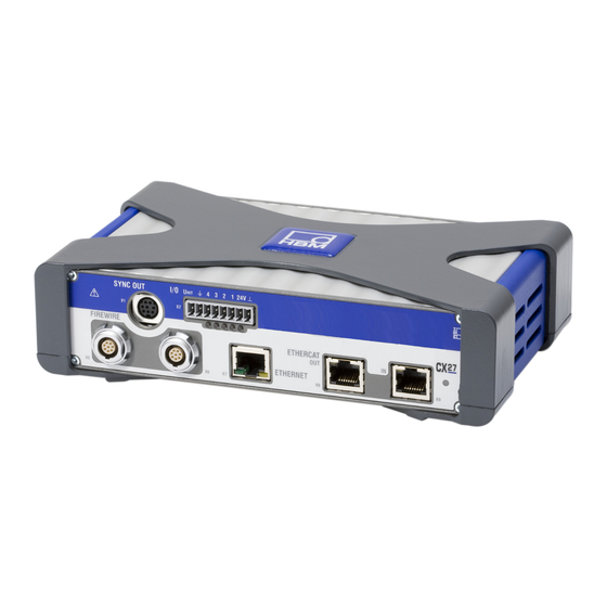
Page 44: Connections
Connections Digital inputs and outputs with LED status display Ethernet connection EtherCAT EtherCAT FireWire connections for output input additional CX27 modules (without supply voltage) Fig.3.1: CX27 Gateway; front Supply voltage VG strip cover X104 X102 X101 X100 FireWire connections for... -
Page 45: Supply Voltage (Socket X104)
Supply voltage (socket X104) There are various ways to supply voltage to the CX27 Gateway module: • With a power pack via socket X104 at the back Socket X104 Input / output Function Supply voltage 10 to 30 V DC (−) -
Page 46: Ethernet (Sockets X7/X100)
Ethernet (sockets X7/X100) The CX27 Gateway has two equivalent Ethernet interfaces, one at the front (X7) and one at the back (X100). Ethernet TCP/IP acts as a central access to all the modules connected to the CX27 Gateway via FireWire. An LED is integrated into each of the connecting sockets to indicate link status and transmission activity. -
Page 47: Digital Inputs And Outputs
Digital inputs and outputs The CX27 provides two digital inputs (pin 1 or 2) and two digital outputs (pin 3 or 4) on a screw terminal plug. The digital IO line can be used in two ways: A) with external power supply •... -
Page 48: Status Display
Status display System LED System LED Green Error-free operation Yellow System not ready, boot procedure running Flashing yellow Download active, identification detection Error, faulty synchronization Ethernet Green LED is lit Ethernet link status is ok Yellow LED flashes Ethernet data transmission ongoing EtherCAT Green LED (Link/Activity LED): EtherCAT has no link... -
Page 49: Accessories
Accessories System accessories Article Description Order No. QuantumX backplane (standard) Backplane for max. 9 modules of the QuantumX family; 1-BPX001 General information: − Wall or control cabinet installation (19”); − Connection of external modules via FireWire possible; − Power supply: 24 V DC; −... -
Page 50: System Accessories
System accessories 9.1.1 BPX001 backplane 9.1.2 Housing connection elements Covers for housings with protection class IP65 Housing clip Housing clip QuantumX... -
Page 51: Voltage Supply
Voltage supply 9.2.1 Power pack NTX001 Europe mains cable NTX001 Mains Modules UK mains cable USA mains cable Australia mains cable Order No.: 1-NTX001 QuantumX... -
Page 52: Supply Cable
9.2.2 Supply cable Approx. 10−15 mm Twisted and tinned Plug ODU Medi-Snap S11M08-P04MJGO−5280 Cable LIYY 2x0.5 mm Order No.: 1-KAB271-3 (length 3 m) FireWire 9.3.1 FireWire cable (module to module; IP20) 0.2 m 2.0 m 5.0m Plug ODU SX1LOC−P08MFG0−0001 Order No.: 1-KAB269-2 (length 2 m) 1-KAB269-0.2 (length 0.2 m) 1-KAB269-5 (length 5 m) - Page 53 Abbreviations Abbreviations Abbreviation Description Controller Area Network, international, standardized protocol (ISO 11898) Category classification of cables also used for Ethernet communication (the minimum classification for EtherCAT cables is Category 5). CAN in Automation (www.can−cia.org) CANOpen over EtherCAT, used as a higher-level protocol Device Description File Electronic Data Sheet ...
- Page 54 Accessories Support Support: E−mail: support@hbm.com Internet: www.hbm.com Headquarters world-wide: Europe Hottinger Baldwin Messtechnik GmbH: Im Tiefen See 45, 64293 Darmstadt, Germany Tel. +49 6151 8030, Fax +49 6151 8039100 E−mail: info@hbm.com www.hbm.com North and South America HBM, Inc., 19 Bartlett Street, Marlborough, MA 01752, USA Tel.
- Page 55 Support QuantumX...
- Page 56 E Hottinger Baldwin Messtechnik GmbH. All rights reserved. All details describe our products in general form only. They are not to be understood as express warranty and do not constitute liability whatsoever. Hottinger Baldwin Messtechnik GmbH Im Tiefen See 45 S 64293 Darmstadt S Germany Tel.
Need help?
Do you have a question about the CX27 and is the answer not in the manual?
Questions and answers