
Summary of Contents for Asentria SiteBoss 571
- Page 1 User’s Manual Installation and Operation Guidelines SiteBoss 571 Remote Site Manager Version 2.10.290 Asentria Corporation 1200 North 96 Street Seattle, Washington, 98103 U.S.A. Tel: 206.344.8800 Fax: 206.344.2116 www.asentria.com...
-
Page 2: Conventions Used In This Manual
No part of this document may be reproduced or electronically transmitted without permission from Asentria Corporation. SiteBoss 571, S571 and EventSensor Type2 are trademarks of Asentria Corporation. -
Page 3: Table Of Contents
Boot Up Sequence ..............................5 Default Passwords ..............................5 Accessing the Command Line ........................... 5 Via a Serial Connection ............................. 5 Via the Asentria OmniDiscover program ........................6 Network Setup ................................6 Via OmniDiscover connection: ........................... 6 Via serial connection: ..............................6 Testing Network Connectivity ............................ - Page 4 Advanced Log Files ..............................121 Transferring Files ..............................122 Appendices ..........................124 Expansion Card Insertion Procedures ........................124 Canadian Department of Communications ......................125 FCC REQUIREMENT: PART 15 ..........................126 General Specifications ............................127 Warranty Information .............................. 128 Asentria Technical Support ...................... 128...
-
Page 5: Quick Start
Connecting to the Unit Out of the box you can communicate with the SiteBoss 571 via the command line or web interfaces, and either serially or over a network. Instructions for each of these methods are provided below. -
Page 6: Via The Asentria Omnidiscover Program
Documentation and Utilities CD, download the OmniDiscover program. This program will allow you to locate devices on your network (i.e.: the S571) with Asentria MAC addresses, and allow you to assign the network settings directly over the network, thus eliminating the need for the serial port connection as described above. -
Page 7: Testing Network Connectivity
Asentria SiteBoss 571 UserManual Testing Network Connectivity 1. Verify that the network router is available to the unit by typing the command PING <IP_address>. A router is always a good candidate to test pings. The following screenshot is an example of a successful ping test. -
Page 8: What Is An S571
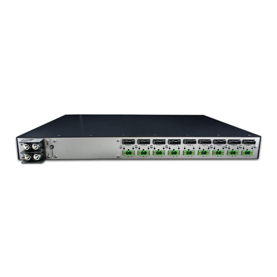
Fig 2: SiteBoss 571 W Optional 30A Power Output back panel The Basics The SiteBoss 571 is a multi-function 1U system that facilitates advanced control and management capabilities into DC powered remote equipment sites. The 9 high-current fused DC power distribution outputs can each deliver up to 10A of current to the load (output voltage is determined by input voltage supplied to unit, 60VDC maximum). -
Page 9: Serial Monitoring (Data Events)
Asentria SiteBoss 571 UserManual Serial Monitoring (Data Events) The S571 has the capability to monitor incoming data for user-defined strings and then report the event via several avenues. The S571 allows for up to 1000 different data events. Each data event can be configured with independent actions, counters, and other unique settings. -
Page 10: Options
Asentria SiteBoss 571 UserManual 1 – Empty slot for a single 30-Amp circuit-breaker-protected power output, or 3 additional 10-Amp fused power outputs. Internal On-board temperature sensor Internal lithium coin-cell type battery backup*/** * Battery backup preserves clock operation when power is not present. Data records and settings are stored in non-volatile memory and therefore do not require battery backup. -
Page 11: Ports, Connectors, Leds And Buttons
The optional AISG module allows a user to tilt an antenna remotely. AISG stands for Antenna Interface Standards Group. They created open specifications for antenna control. For more information on this option please see the AISG Remote Antenna Controller Feature Guide available on the Asentria Product Information Portal or contact Asentria Technical Support. -
Page 12: Usb Ports
The LEDs by each Ethernet connection on the back panel flicker when packets are being transmitted/received on that port. The S571 features network connectivity via Secure Shell (SSH) and Secure FTP (SFTP). Refer to the Securing a SiteBoss Application Guide on the Asentria Product Information Portal for a detailed explanation of SSH and SFTP. Page 12... -
Page 13: Front Panel Leds
Asentria SiteBoss 571 UserManual Internal I/O contacts 4 pair of contact points plus a power output, configured from right to left as follows: 4 pair of dry contact points. These appear as the internal 4-CC inputs on the EventSensor Device Settings menu. -
Page 14: Back Panel Ports & Connectors
Each power connector is protected by a GMT fuse – minimum rating 12A when runnng loads that approach 10A. Fuses may be provided by Asentria, but normally are provided by the end user. Asentria recommends using fuses rated at 20% higher current than the expected load. - Page 15 Asentria SiteBoss 571 UserManual Back Panel LEDs Power Output LEDs Each power output connector on the back panel has two LEDs associated with it – one on the Right of the port (labeled “S”), one on the Left of the port (labeled “A”).
-
Page 16: Navigating The Interface
The option list type is similar to the toggle type in that it has a list of options to choose from. The letter adjacent to the option would be selected to choose that option. SiteBoss 571 - Console Baud Rate A) 300... -
Page 17: Actions List
Asentria SiteBoss 571 UserManual After selecting an option, you are immediately returned to the previous menu. The new value will be displayed to the right of the setting name, letter, or number. Alarm Actions (Actions List) Alarm actions have their own unique method of entry. The basics are commented on in the following pages. - Page 18 Send an SNMP inform to a specific IP address or index which refers to an IP address or host name configured in Actions Definitions menu. INFORM(IPADDRESS OR INDEX#) Malert Malert sends a malert (Asentria Alarm via modem) to a number specified by index number, which can be configured in the Actions Definitions menu. MALERT(PHONE# or INDEX#)
- Page 19 SMS(PHONE# OR INDEX#) Talert Send a talert (Asentria Alarm via TCP) to a server identified by a hostname index defined in Actions Definitions menu or by an IP address specified in the action list. TALERT(IPADDRESS OR INDEX#)
-
Page 20: Web Interface
Asentria SiteBoss 571 UserManual Web Interface The S571 has a built-in HTTP web server that can be used to configure the unit from anywhere the unit can be accessed on the network or Internet. This interface is enabled by default. Simply connect to http://<IP address of S571>... -
Page 21: The Status Pages
Asentria SiteBoss 571 UserManual The Status Pages The S571 status screens are this unit's one-stop informational source. Most of the information that a user would need to know about the unit is displayed on these screens. This section outlines the different status screens and highlights why they are useful. -
Page 22: Power Distribution Status
Total Power Total Power displays the total power drawn by the S571 and all of the power distribution outputs (Main Voltage x Total Current). SiteBoss 571 Current SiteBoss 571 Current displays only the current drawn by the S571. Page 22... -
Page 23: Eventsensor Status
Configuration of these sensors must still be done in the appropriate setup menu. Below is a screenshot of a SiteBoss 571 configuration. Your setup will likely differ significantly depending on installed sensors and slot cards. SiteBoss 571 Current EventSensor Status... -
Page 24: Setup Menu
The Main Setup Menu contains all of the configuration options available on the S571. It is accessed by typing SETUP followed by <Enter> at the SiteBoss command prompt, and is organized in a logical tree structure with all settings classified under the following groups. SiteBoss 571 - Main Setup Menu A) Network Settings B) Serial Settings... -
Page 25: Network Settings
This option allows for immediate toggling or timed activation of devices connected to the power output terminals. Network Settings The Network Settings menu contains all of the options pertaining to network communication. SiteBoss 571 - Network Settings A) Ethernet Settings B) IPv4 Default Router... - Page 26 Event Sensor Reporting Settings This selection displays the Event Sensor Reporting menu where the parameters for using Event Sensors on other Asentria site monitoring hosts can be configured. SNMP Settings The SNMP Settings option displays the SNMP Settings menu where you can configure the version of SNMP to use, the community names, and trap settings.
-
Page 27: Ethernet Settings
VLAN Settings What follows is a top-level overview of the SiteBoss VLAN settings. Refer to the IP Routing & Restrictions Feature Guide on the Asentria Product Information Portal for a detailed explanation of VLANs. Page 27... -
Page 28: Ipv6 Settings
IPv4 VLAN mode and another interface operating in IPv6 AUTO mode. But the user could not have the same Ethernet interface operating in both IPv4 VLAN mode and IPv6 AUTO or STATIC mode. SiteBoss 571 - Ethernet 1 IPv6 Settings A) Mode [OFF]... -
Page 29: Name Resolution Settings
If you configure the Mode to Static use this option to set the IPv6 default router. Name Resolution Settings The Name Resolutions Settings menu can be used to configure the IP Addresses of up to two Domain Name Servers (DNS). SiteBoss 571 - Name Resolution Settings A) DNS Server 1 [0.0.0.0] B) DNS Server 2 [0.0.0.0]... -
Page 30: Event Sensor Reporting Settings
EventSensor Reporting Host Port This is used to set the TCP Port that this S571 will use for receiving sensor reports from another Asentria device. For a further explanation of EventSensor Reporting, refer to the EventSensors Feature Guide on the... - Page 31 SiteBoss to query other devices using SNMP. Trap Settings This menu is used to configure whether to send authentication failure traps and notification settings. SiteBoss 571 - Trap Settings A) Authentication Failure Traps [OFF] B) Notification Attempts (0=infinite)
- Page 32 SiteBoss 571 - SNMP Poll Request Settings A) Request 1 . . . P) Request 16 Enter your Selection: A SiteBoss 571 - SNMP Poll Request 1 Settings A) Description B) Agent IP Address C) Read Community [public] D) OID...
-
Page 33: Ftp Settings
No data is pushed with this command. Connection data displayed on the terminal screen is useful if the connection fails. An immediate push of data can be done using the PUSHNOW command from the command prompt. SiteBoss 571 - FTP Settings A) FTP Push Enable [OFF]... -
Page 34: Ppp Settings
Select Files to Push displays the FTP File Selection menu where you can select which files are pushed by toggling ON or OFF. The default setting for all is ON, except for Audit Log, which is OFF. SiteBoss 571 - FTP File Selection A) Data File 1 [ON] . - Page 35 PPP dialout in order to maintain reliable network connectivity for sending SNMP traps. PPP Dialout Settings This menu is used to configure settings pertaining to making outbound PPP network connections for an optional POTs modem. SiteBoss 571 - PPP Dialout Settings A) PPP Dialout Enabled [OFF] B) Phone Number 1...
- Page 36 Values are ON or OFF (default). ON means that if FTP push raised PPP, then it kills PPP when finished. PPP Hosting Settings This menu is for configuring settings for hosting a PPP connection on the option POTs Dial-Up Modem. SiteBoss 571 - PPP Hosting Settings A) PPP Hosting Enabled [OFF]...
-
Page 37: Email Settings
Real-Time Sockets are used to collect data on TCP port 2201 from a serial port in real-time, while buffering data if the network connection goes down. Each file can be configured independently. Refer to the Telnet Feature Guide on the Asentria Product Information Portal for a detailed explanation of Real-Time Sockets or contact Asentria Technical Support. -
Page 38: Snmp Trap Capture Settings
A) FILE1 . . . P) FILE16 Q) EVENTS Enter your Selection: A SiteBoss 571 - FILE1 Real-Time Data Socket Setup A) Real-Time Socket Mode [LISTEN] B) Show Answer String on Connection [ON] C) Require Xon to Start Data Flow... -
Page 39: Ip Address Restrictions
Asentria SiteBoss 571 UserManual Refer to the SNMP Operations Feature Guide on the Asentria Product Information Portal for a detailed explanation of SNMP Trap Capture or contact Asentria Technical Support. SiteBoss 571 - SNMP Trap Capture Settings A) SNMP Trap Capture Enable... -
Page 40: Routing Settings
Asentria SiteBoss 571 UserManual SiteBoss 571 - IP Address Restrictions 1. 0.0.0.0 2. :: A) Add Item to Table B) Delete an Item from Table C) Delete All Items from Table Routing Settings The following is a top-level overview of the S571 routing settings. For more detailed configuration and use instructions for all of these please refer to the IP Routing &... - Page 41 Enter your Selection: A SiteBoss 571 - Port Forwarding Settings A) Route 1 . . . P) Route 16 Enter your Selection: A SiteBoss 571 - Port Forwarding Settings for Route 1 A) Mode [OFF] B) Source Interface [NONE] C) Source Port...
- Page 42 Ethernet to Wireless Settings enable the SiteBoss to forward IP frames originating on Ethernet that are not IP- addressed to the unit as well as forward IP frames received on a wireless interface that are associated with forwarded frames that originated on Ethernet. SiteBoss 571 - Ethernet to PPP/Wireless Settings A) Enable [OFF]...
- Page 43 B) Route 2 [0.0.0.0] C) Route 3 [0.0.0.0] D) Route 4 [0.0.0.0] Enter your Selection: A SiteBoss 571 - Web Login Forwarding Settings for Route 1 A) Ingress Destination Port [8080] B) Egress Destination IP Address [0.0.0.0] C) Egress Destination Port [80]...
-
Page 44: Dsl Settings
The following describes the menu options for configuring the optional ADSL Modem. For more information regarding the operation of the ADSL modem please refer to the Configuring and Using an Asentria Internal ADSL Modem Feature Guide on the Asentria Product Information Portal or contact Asentria Technical Support. SiteBoss 571 - DSL Settings... -
Page 45: Vpn Settings
Asentria Technical Support. SiteBoss 571 - VPN Settings A) VPN 1 B) VPN 2 Enter your Selection: A SiteBoss 571 - VPN 1 Settings A) Mode [OFF] B) Start Mode [MANUAL] C) Description D) Remote Host E) Public Interface... -
Page 46: Ipsec Settings
This is a basic description of settings and options for an IPsec VPN. For more information refer to the Configuring and Using an IPsec VPN Feature Guide on the Asentria Product Information Portal or contact Asentria Technical Support. SiteBoss 571 - VPN 2 IPsec Settings A) Remote Network [0.0.0.0/0]... -
Page 47: Ssl Settings
This is an on/off toggle to enable or disabled perfect forward secrecy on the tunnel. SSL Settings Use this menu for configuring the settings if the Mode is SSL Client or SSL Server. SiteBoss 571 - VPN 2 SSL Settings A) Protocol [UDP] B) Port... -
Page 48: Cpe Settings
Enter your Selection: A SiteBoss 571 - CPE Settings A) CPE 1 ..P) CPE 16 Enter your Selection: A SiteBoss 571 - CPE 1 Settings A) IP Address B) Name C) Description D) Alarm Keep-alive Period (seconds) E) Alarm Threshold... -
Page 49: Serial Settings
There are two different types of serial port configuration menus in the S571. The console port settings and the sixteen serial data port (indicated by “n-I/O n”) settings. SiteBoss 571 - Serial Settings A) Console Settings B) 1-I/O 1 Settings . - Page 50 This option displays a menu that allows you to select whether the Date/Time and/or the Site Name are pre-pended to each incoming data string. The default setting for Date/Time Stamping and Site Name Stamping is OFF. SiteBoss 571 - Serial 1 Record Stamping A) Date/Time Stamping...
- Page 51 Asentria SiteBoss 571 UserManual SiteBoss 571 - Store Data To A) FILE1 [ON] B) FILE2 [OFF] C) FILE3 [OFF] D) FILE4 [OFF] E) FILE5 [OFF] F) FILE6 [OFF] G) FILE7 [OFF] H) FILE8 [OFF] I) FILE9 [OFF] J) FILE10 [OFF]...
-
Page 52: Modem Settings
Asentria SiteBoss 571 UserManual SiteBoss 571 - Serial Port 1 Multiline Record Settings A) Multiline Record Enable [OFF] B) Blank Line Count C) Complex Multiline Detection [OFF] Multiline Record Enable This is an ON/OFF toggle to enable multiline record detection. The default setting is OFF. -
Page 53: Dialup Modem
Dialup Modem The following is a top level settings configuration overview for the optional Dialup POTs modem card. For additional information see the Dial Up Modem Feature Guide on Asentria Product Information Portal or contact Asentria Technical Support. CAUTION – To reduce the risk of fire, use only No. 26 AWG or larger telecommunication line cord. -
Page 54: Wireless Modem
Note: Caller ID must be available on the phone line connected to the S571 for this feature to work. SiteBoss 571 - Caller ID Security A) Enable... - Page 55 Hosting. The default is ON. For wireless modem conductivity the firewall will need to be changed to OFF. Advanced Settings The Advanced Settings displays a menu allowing for additional configuration of Wireless Modem Settings. SiteBoss 571 - Wireless Modem Advanced Settings A) Idle Timeout (minutes) B) Keep-Alive Threshold (minutes)
-
Page 56: Security Settings
The Security Settings menu displays options for setting the security mode, as well as specific and general security settings. See the Securing a SiteBoss Feature Guide on the Asentria Product Information Portal or contact Asentria Technical Support for more information. -
Page 57: Specific Security Settings - User Profile Security Settings
When the Security Mode is toggled to USER PROFILES the User Profile Settings will display at Specific Security Settings. This menu is used to configure up to twelve User Names and Passwords along with user specific access permissions and routing. SiteBoss 571 - User Profile Security Settings A) User 1: admin/********/COMMAND/FILE1 B) User 2:... - Page 58 This option displays a menu allowing you to toggle ON or OFF access via Local (Console Port), Modem, Telnet, FTP, Real-Time Socket, SSH and Web Portal. These are abbreviated: LMTFRSsW and the default setting for all is ON. SiteBoss 571 - Allowed User Connection Via A) Modem [ON]...
- Page 59 This selection toggles through the actions available to the user if they are given access to the command prompt. Options are MASTER, NONE, VIEW, ADMIN1, ADMIN2, and ADMIN3. See the User Profiles Feature Guide the Asentria Information Portal for more information on each access level. The default setting is MASTER. Page 59...
- Page 60 That code must be plugged into a program called Response Code Generator (RCG). This software can be found on the Documentation and Utilities CD. Contact Asentria for more information on how to use or obtain this application. RCG requires a shared secret as well as the challenge code generated by the S571.
-
Page 61: Authentication Settings
That code must be plugged into a program called Response Code Generator (RCG). This software can be found on the Documentation and Utilities CD. Contact Asentria for more information on how to use or obtain this application. RCG requires a shared secret as well as the challenge code generated by the SiteBoss. -
Page 62: Specific Security Settings - Radius Security Settings
Shared Secret for Challenge/Response This selection sets the shared secret used to generate Challenge/Response codes. (Maximum length 48 chars) Challenge/Response requires the use of the free Asentria Response Code Generator program. for this, or download (named “Password Generator”) from the Asentria... -
Page 63: General Security Settings
This will display a menu tree which contains the event settings options. Refer to the Data Events Feature Guide on the Asentria Product Information Portal for an example-driven approach to defining alarm definitions or contact Asentria Technical Support for more information. -
Page 64: Class Table
Asentria SiteBoss 571 UserManual SiteBoss 571 - Alarm/Event Definitions Menu A) Class Table B) Data Alarm/Filter Settings C) EventSensor Device Settings D) No-Data 1 Alarm Settings [OFF] E) No-Data 2 Alarm Settings [OFF] F) Scheduled Event 1 Settings [OFF] G) Scheduled Event 2 Settings... -
Page 65: Data Alarm/Filter Settings
The class number and name are reported in Asentria Alarms, and SNMP traps. It is a mechanism for you to provide varying severities for different alarms so that you can act on them upon receipt. - Page 66 A) Macro 1 P) Macro 16 Q) Next Macro Page Enter your Selection: A SiteBoss 571 - Settings for Data Alarm Macro 1 A) Name B) Equation Name The macro name is the name by which the macro is referenced in any data alarm equation, and can be up to 16 characters in length.
- Page 67 16 data alarm/filters (1-16, 17-32, etc.) electing the Next or Previous Page Selection Screen. This will display a menu where you can select from those 16 data alarm options. SiteBoss 571 - Data Alarm/Filter Settings A) Alarm/Filter Page 1 (Alarms 1-16) B) Alarm/Filter Page 2 (Alarms 17-32)
- Page 68 Asentria SiteBoss 571 UserManual SiteBoss 571 - Settings For Data Alarm/Filter 1 A) Alarm/Filter Enable [OFF] B) Alarm/Filter Mode [ALARM] C) Alarm/Filter Name D) Alarm/Filter Equation E) Threshold F) Auto-Clear when Threshold Reached [ON] G) Alarm Counter Clear Interval [12 HOURS]...
-
Page 69: Eventsensor Device Settings
S571. For more information on configuring EventSensors see the EventSensors Feature Guide on the Asentria Product Information Portal or contact Asentria Technical Support. SiteBoss 571 - Sensor Events Menu Name Alive Number Configuration A) INTERNAL -------- 1-TS 4-CC 9-PW <none>... - Page 70 Power Distribution points on the back panel of the S571. EventSensor Reporting Enabled This is an ON/OFF toggle to enable/disable the function which allows an Asentria unit to transmit EventSensor data to another Asentria unit. For EventSensor reporting function to work the EventSensor Reporting Settings under the Network Settings menu will need to be configured.
- Page 71 In the case of Very High or High levels, the alarm will occur as the temperature rises above the setting. In the case of Low or Very Low, the alarm will occur as the temperature drops below the setting. SiteBoss 571 - Internal Temperature Event Settings A) Very High Event Temperature [100.0]...
- Page 72 The S571 has four internal contact closures. They are located under the USB ports on the front panel. The contact closures may be configured to alarm in either the open or closed state, depending on the needs of the attached device. SiteBoss 571 - Internal Contact Closure Event 1 A) Sensor Name [unnamed]...
- Page 73 The default setting is 120 minutes. Output n These are the control and alarm settings for the nine fuse protected DC power distribution outputs. SiteBoss 571 - External Output Event 1 Device Number: 0 Device ID: 0C000000...
- Page 74 In the normal state, the host unit stops retrieving the battery voltage from the rectifier. For more information see the Global Load Shedding Settings chapter, the Load Shedding Feature Guide on the Asentria Product Information Portal or contact Asentria Technical Support. Page 74...
- Page 75 Asentria SiteBoss 571 UserManual SiteBoss 571 - Load Shedding Settings for Output 1 Device Number: 0 Device ID: 0C000000 Device Name: INTERNAL A) Enable [OFF] B) Voltage Threshold (tenths of volts) [480] C) Voltage Shutoff Delay (minutes) D) Time Shutoff Delay (minutes)
- Page 76 Current and Voltage Sensors for power used by the SiteBoss, and the Current and Fuse Sensors for each of the individual power distribution outputs. SiteBoss 571 - MAIN Power Distribution Settings Device Number: 200 Device ID: 0C000000...
- Page 77 Asentria SiteBoss 571 UserManual SiteBoss 571 MAIN Current Sensor Event Device Number: 200 Device ID: 0C000000 Device Name: INTERNAL A) Very High Event Value (mA) [120000] B) Very High Event Actions C) Very High Event Trap Number [180] D) Very High Event Class...
- Page 78 Asentria SiteBoss 571 UserManual SiteBoss 571 - MAIN Voltage Sensor Settings Device Number: 200 Device ID: 0C000000 Device Name: INTERNAL A) Voltage Sensor Enabled [OFF] B) Deadband (mV) [20] C) Very High Event Settings [58000] [190] [Info] D) High Event Settings...
- Page 79 Unnamed n - Power Output Current Sensor Events These menus are used to configure the current sensor alarm actions and thresholds for each individual power output. SiteBoss 571 - Power Distribution Settings for Output 1 Device Number: 200 Device ID: 0C000000...
- Page 80 Return to Normal Settings This menu is used to configure actions for the SiteBoss to take when the current readings return to the defined normal range. SiteBoss 571 - Current Sensor Event for Output 1 Device Number: 200 Device ID: 0C000000...
- Page 81 Fuse Sensor Events This menu is used to enable the Fuse Sensor and configure event notifications. SiteBoss 571 - Fuse Sensor Settings for Output 1 Device Number: 200 Device ID: 0C000000...
- Page 82 EventSensor option will bring up a menu where event thresholds and actions can be configured. Refer to the EventSensors Feature Guide on the Asentria Product Information Portal or contact Asentria Technical Support more information. SiteBoss 571 - Sensor Events Menu Name Alive Number Configuration A) Internal Sensors...
- Page 83 SiteBoss 571 - Fuel Sensor Settings A) Fuel Sensor 1 B) Fuel Sensor 2 C) Fuel Sensor 3 Enter your Selection: A SiteBoss 571 - Settings for Fuel Sensor 1 A) Enable [OFF] B) Sensor Type [CURRENT] C) Name...
- Page 84 Asentria SiteBoss 571 UserManual Level Measurement Settings This menu is used to configure the fuel level measurement settings. SiteBoss 571 - Level Measurement Settings for Fuel Sensor 1 A) Analog Input Eventsensor [200] B) Analog Input Point C) Distance Unit...
- Page 85 Up to 32 height/volume pairs can be entered. Volume Event Settings This menu is used for configuring alarm notifications based on changes in the fuel level. SiteBoss 571 - Volume Event Settings for Fuel Sensor 1 A) Event Enabled [OFF] B) Deadband [6.0]...
- Page 86 Select one to be assigned to this event. The default is Info. Disconnect Event Settings This menu is for configuring alarm notifications of the fuel sensor being disconnected. SiteBoss 571 - Disconnect Event Settings for Fuel Sensor 1 A) Event Enabled [OFF]...
- Page 87 The AC Power Monitor Settings menu is used to configuring up to six AC Power Monitors. Refer to the AC Power Monitoring Feature Guide on the Asentria Product Information Portal for a more in-depth explanation of configuring AC power monitoring or contact Asentria Technical Support for more information.
- Page 88 SiteBoss 571 - Average Voltage Settings for AC Power Monitor 1 A) Event Settings B) System Reporting Settings Enter your Selection: A SiteBoss 571 - Average Voltage Event Settings for AC Power Monitor 1 A) Event Enabled [OFF] B) Deadband [3.0]...
- Page 89 Very High / High / Return to Normal / Low / Very Low Average Voltage Event Settings These options display submenus where the event action settings can be configured for each event level. SiteBoss 571 - Average Voltage Event Settings for AC Power Monitor 1 A) Very High Event Value [253.0]...
- Page 90 Very High / High / Return to Normal / Low / Very Low Average Voltage Event Settings These options display submenus where the event action settings can be configured for each event level. SiteBoss 571 - Average Current Event Settings for AC Power Monitor 1 A) Very High Event Value [30.0]...
- Page 91 SiteBoss 571 - Total Real Power Settings for AC Power Monitor 1 A) Event Settings B) System Reporting Settings Enter your Selection: A SiteBoss 571 - Total Real Power Event Settings for AC Power Monitor 1 A) Event Enabled [OFF] B) Deadband [30.0]...
- Page 92 Very High / High / Return to Normal / Low / Very Low Event Settings These options display submenus where the event action settings can be configured for each event level. SiteBoss 571 - Total Real Power Event Settings for AC Power Monitor 1 A) Very High Event Value [7500.0]...
- Page 93 Return to Normal / Low / Very Low Event Settings These options display submenus where the event action settings can be configured for each event level. SiteBoss 571 - Total Power Factor Event Settings for AC Power Monitor 1 A) Low Event Value [0.85]...
- Page 94 This menu covers the global settings for the Load Shedding functions within the SiteBoss. Each Individual power output will have its own individual load shedding menu to configure load shedding options individually. See the Load Shedding Feature Guide on the Asentria Product Information Portal or contact Asentria Technical Support for more information.
-
Page 95: No-Data N Alarm Settings
“after hours” when call volumes are lighter and the periods of time where there is "no data“ might be longer. SiteBoss 571 - No-Data Alarm 1 Settings A) Alarm Enable... -
Page 96: Scheduled Event N Settings
Scheduled Events allow you to schedule a specific date/time for an alarm action to occur. For example, you might want the SiteBoss to send you an email every morning at 8:00 just so you know it is live on the network. SiteBoss 571 - Scheduled Event 1 Setup A) Enable Event... -
Page 97: Serial Handshaking Alarm Settings
I/O n Serial Handshaking Alarms These options display a menu for configuring alarming on serial DTR handshaking conditions for the specified serial port. SiteBoss 571 - I/O 1 Serial Handshaking Alarms A) Serial Handshaking Low Alarm Enable [OFF] B) Serial Handshaking Low Alarm Actions []... -
Page 98: Cpe Alarm Settings
These settings are used for configuring Customer Premises Equipment (CPE) monitoring functions. Configure the equipment to monitor under Network Settings/CPE Settings. Contact Asentria Technical Support for more information. SiteBoss 571 - CPE Alarm Settings A) Alarm Enable [OFF] B) Alarm Actions C) Alarm Trap Number [511] D) Alarm Class... -
Page 99: Reset Event Settings
The Reset Event Settings are used to configure event actions to be performed after the unit has been restarted. These actions would be executed regardless of whether the unit was reset via a restart command or by power cycling. SiteBoss 571 - Reset Event Settings A) Enable Event [OFF]... -
Page 100: Action Definitions
Asentria SiteBoss 571 UserManual Action Definitions This menu is where a majority of the actions possible when events are detected are configured. SiteBoss 571 - Actions Definition Menu A) Hostname/IP Address 1 B) Hostname/IP Address 2 C) Hostname/IP Address 3... -
Page 101: Action Settings Menu
Asentria SiteBoss 571 UserManual SiteBoss 571 - Pager 1 Settings A) Pager Type [NUMERIC] B) Pager Callout Number C) Pager ID D) Numeric Message E) Post Callout Delay (seconds) [15] F) Post ID Delay (seconds) Pager Type This toggles between NUMERIC and ALPHA to select the type of pager to call. The default is NUMERIC. -
Page 102: General Settings
Asentria Alarm Version This option toggles between 1.0 and 1.1 to indicate which type of Asentria Alarm notification will be displayed. Set this 1.0 for the Dialup POTs modem. Set it at 1.1 if you are using other delivery methods for your alarm actions. -
Page 103: Date/Time Setup
Asentria SiteBoss 571 UserManual Site Name This is a text string to set the name assigned to this SiteBoss. This name is included with alarm messages (Traps, Emails, etc.) and is displayed at the top of the Status screen. The name should be unique for clarity (maximum length 40 chars). - Page 104 Asentria SiteBoss 571 UserManual SiteBoss 571 - System Date/Time A) Current Date [12/16/2010] B) Current Time [14:46:21] C) Adjust for Daylight Savings [ON] D) GMT Difference (hours) E) GMT Difference Direction [BEHIND] F) Enable Time Protocol [OFF] G) Time Servers Current Date The date can be manually set using this field.
-
Page 105: Event Log Settings
Asentria SiteBoss 571 UserManual Event Log Settings The Event Log is a record of all data and sensor events that occur within the S571. SiteBoss 571 - Event Log Settings A) List Events File B) Clear Events File C) Enable Events Log File... - Page 106 Asentria SiteBoss 571 UserManual SiteBoss 571 - Audit Log Settings A) List Audit Log File B) Clear Audit Log File C) Enable Audit Log File [ON] D) Maximum File Size [128] E) Store Reset Incidents [ON] F) Store Command Entry...
-
Page 107: Scripting Settings
Utilizing Lua scripting on a SiteBoss can be a complex process. In order to assist in the implementation of custom Lua scripts, Asentria has created a Scripting Feature Guide on the Asentria Product Information Portal, which goes into further detail regarding the creation and usage of Lua scripts on a SiteBoss product. SiteBoss 571 - Scripting Settings... -
Page 108: Output Control
Asentria SiteBoss 571 UserManual SiteBoss 571 - Script 1 Settings A) Enable [OFF] B) Name C) File Name D) Run Always [OFF] E) Run At Startup [OFF] F) Run At Scheduled Time [OFF] G) Repeat Interval (minutes) H) Arguments I) Start Script Now... - Page 109 This option displays a menu from which a period of time can be selected to change the current state of the selected output, before is changes back to the state it is in now. SiteBoss 571 - Timed Output Operation Device: INTERNAL...
-
Page 110: Output Power-Up Sequence
Asentria SiteBoss 571 UserManual Output Power-Up Sequence Note: This feature applies to both the integral power controller board on the S571, and any connected PowerBoss devices. In this section the term “power controller" refers to either device. This feature allows the user to modify the behavior of the power switches after the unit is powered up. By default, the switches are all turned on within a few seconds of power-up. - Page 111 Asentria SiteBoss 571 UserManual • A value of 0 for a timeout means "forever" (this is consistent with other timeout usages in Asentria products), subject to the overall timeout specified by event.power[X].powerup.timeout. Once a valid sequence has been successfully set, it will be executed the next time the power controller is powered up or reset.
-
Page 112: Event.power[X].Powerup.timeout
If it is not in sync with the power controller (i.e. it is changed while the sequence is running), then it may not accurately reflect which step is currently being executed. >powerup status 200 SiteBoss 571 Power-up Sequence Status for Controller 200 Sequence complete: NO Time in sequence : 00:08:41... -
Page 113: Types Of Alarm Notices
Support). The first trap is a ‘Standard’ SNMP trap. This is the original SNMP trap format supported by Asentria products. In this trap there are two name/value pairs in the trap payload; ‘siteName’ which is the sitename of the device sending the trap and ‘stockTrapString’... -
Page 114: Email Alarms
Version 1.1 (default) for TCP An Asentria Alarm sent via TCP is called a Notice. A notice is a piece of data formatted in printable ASCII: a set of lines delimited by CRLF. Each line is of the format <field>: <data>CRLF. The first line has <field> = "ID" (without the quotes). - Page 115 VPNG Down Alarm notice Version 1.0 for modem dialout An Asentria Alarm can also be sent over dial-up modem when the Asentria Alarm Version is set to 1.0. Details of this alarm follow: When an Asentria Alarm is initiated, the box dials into the callout number specified by the action. Once connected, it sends a header and waits for a specific response.
-
Page 116: Sms Alarms
If Require Asentria Alarm ACKs is enabled, the S571 will require a positive CRC mode response or it will disconnect and retry the call. To enable CRC, the receiver must respond with the following after the header is... -
Page 117: Pager Alarms
Asentria SiteBoss 571 UserManual Date Time :: SiteName :: Sensor Pod/Bank name :: Sensor Point Name :: Alarm Alias For example, a typical SMS message for a temperature alarm might look like the following: 09/25 15:59 :: San Diego Site #12 :: Sensor Pod 12 :: Cabinet Temp :: Temperature Very High SMS alarm messaging has the following limitations: ... - Page 118 Asentria SiteBoss 571 UserManual Power output actions are declared with the following syntax: Power: output(action, EventSensor, point) Put an output in a certain state specified by action. action: one of the following words, by case-insensitive exact match or partial unambiguous match: on or off ...
-
Page 119: Device Administration
Asentria SiteBoss 571 UserManual Device Administration Backing Up & Restoring Settings CLI Backup In order for this process to work a terminal emulator that supports either session logging or Xmodem transfer is required. Examples of open source emulators that support at least one of these are TeraTerm, Poderosa, and PuTTY. -
Page 120: Firmware Upgrade
Firmware Upgrade Contact Asentria Tech Support to obtain the update file and save it to a directory on your PC or an FTP server. Upgrades can be done via several methods, by transferring and updating via the S571 web Interface, by sending the update file from another host to the S571’s FTP server, or by using the S571’s FTP client to get the update file. -
Page 121: Advanced Log Files
Asentria SiteBoss 571 UserManual Depending on the software version your Administration page may have someone different looks but the function remains constant. The new Web Interface will look like this. Note: While the S571 is processing the update file, it is very important that the unit not be power-cycled, nor should the Reset button be pushed. -
Page 122: Transferring Files
Asentria SiteBoss 571 UserManual SiteBoss command line, type "ping 8.8.8.8". This will begin a recurring ping test. Press ctrl + C in order to stop the test. If experiencing a specific problem perform the steps to reproduce the problem. 4. Issue the command "tcplog off". - Page 123 Asentria SiteBoss 571 UserManual The syntax for receiving files from another machine to the S550 is: put [path to file] The syntax for sending files from the S550 to another machine is: get [filename] [path to file] [filename] This is the exact name of the file including any extensions.
-
Page 124: Appendices
Asentria SiteBoss 571 UserManual Appendices Expansion Card Insertion Procedures The S571 can be purchased with a variety of optional Expansion Cards that are normally inserted in the expansion bays on the front panel of the unit when it is built at the factory. Expansion Cards can also be purchased separately and inserted by field technicians after the unit has been installed in the field. -
Page 125: Canadian Department Of Communications
Asentria SiteBoss 571 UserManual Canadian Department of Communications NOTICE: The Canadian Department of Communications Label identifies certified equipment. This certification means that the equipment meets certain telecommunications network protective, operational and safety requirements. The Department does not guarantee the equipment will operate to the user's satisfaction. -
Page 126: Fcc Requirement: Part 15
Asentria SiteBoss 571 UserManual L'indice de charge (IC) assigné a chaque dispositif terminal indique, pour éviter toute surcharge, le pourcentage de la charge totale qui peut etre raccodée a un circuit téléphonique bouclé utilisé par ce dispositif. La terminaison du circuit bouclé... -
Page 127: General Specifications
30A output is 30A maximum continuous rating @40-60VDC. Note: Asentria recommends using fuses rated at 20% higher current than the expected load. Caution: Do not exceed maximum ratings for any outputs. Power outputs and relays are only designed for DC power distribution with SELV limits (60VDC Max), and are not intended to control AC powered devices. -
Page 128: Warranty Information
Warranty Information Asentria Corporation hereby warrants that it will, as the buyers sole remedy, repair or replace, at its option, any part of the S571 which proves to be defective by reason of improper materials or workmanship, without charge for parts or labor, for a period of 12 (twelve) months.
Need help?
Do you have a question about the SiteBoss 571 and is the answer not in the manual?
Questions and answers