
Subscribe to Our Youtube Channel
Related Manuals for Lenze 2175

Summary of Contents for Lenze 2175
-
Page 1: Operating Instructions
Show/Hide Bookmarks EDB2175EN 00423117 Operating Instructions Fieldbus module type 2175 DeviceNet / CANopen Phone: 800.894.0412 - Fax: 888.723.4773 - Web: www.actechdrives.com - Email: info@actechdrives.com... - Page 2 E 2001 Lenze GmbH & Co KG No part of this documentation may be copied or made available to third parties without the explicit written approval of Lenze GmbH & Co KG. All information given in this online documentation has been carefully selected and tested for compliance with the hardware and software described. Neverthe- Phone: 800.894.0412 - Fax: 888.723.4773 - Web: www.actechdrives.com - Email: info@actechdrives.com...
-
Page 3: Table Of Contents
Show/Hide Bookmarks Contents 1 Preface and general information ......... . . How to use these Operating Instructions . - Page 4 ..............Drive enable via 2175 fieldbus module .
- Page 5 Show/Hide Bookmarks Contents 6 Parameter setting ............Structure of a CAN data telegram .
- Page 6 6-44 6.5.2 Description of communication-relevant Lenze codes ....... . 6-47 6.5.2.1...
- Page 7 11-3 11.5 Drive enable via 2175 fieldbus module ..........
- Page 8 14.1.1 Integration of LENZE-EDS files into “RSNetWorx” ........
-
Page 9: Preface And General Information
In the following, the term ”controller” is used for ”93XX servo inverters” or ”82XX frequency inverters”. Drive system In the following the term ”drive system” is used for drive systems with fieldbus modules and other Lenze drive components. Fieldbus module In the following text, the term ”fieldbus module”... -
Page 10: Legal Regulations
• The fieldbus module is an accessory module and can be optionally attached to the following Lenze controllers: 820X, 821X, 822X, 8200 vector, 9300 servo 9300 servo PLC. The 2175 fieldbus module links Lenze controllers with the fast serial communication system CAN. -
Page 11: Safety Information
General safety information • These safety notes do claim to be complete. In case of questions and problems please contact your Lenze representative. • At the time of delivery the fieldbus module meets the state of the art and ensures basically safe operation. -
Page 12: Layout Of The Safety Information
Show/Hide Bookmarks Safety information DeviceNet und CANopen Layout of the safety information • All safety information has a uniform layout: – The icon characterizes the type of danger. – The signal word characterizes the severity of danger. – The note text describes the danger and gives information how to prevent dangerous situations. -
Page 13: Canopen
Application Layer). All mandatory parts of the CiA DS301 protocol, version 4.01 have been implemented in the 2175 bus module. Features • Attachable module for the following Lenze controller series: 82XX, 8200 vector, 93XX 9300 servo PLC. • The front DIP switch enables easy setting of –... -
Page 14: General Data And Application Conditions
0 V AC No electrical isolation Pollution degree VDE0110, part 2, pollution degree 2 Dimensions DeviceNet CANopen Fig. 3-1 Dimensions: 2175 fieldbus module (all dimensions in mm) Phone: 800.894.0412 - Fax: 888.723.4773 - Web: www.actechdrives.com - Email: info@actechdrives.com BA2175 EN 2.0... -
Page 15: Communication Times
Show/Hide Bookmarks CANopen Technical data 3.5.1 Communication times Note! The CAN bus communication times depend on • Processing time in the controller • Baud rate • Data priority • Bus load More information about bus access control can be obtained from corresponding literature specialised on Controller Area Networks. -
Page 16: Telegram Time
Show/Hide Bookmarks CANopen Technical data 3.5.1.2 Telegram time Telegram times depend on the baud rate and telegram length: Data length [byte] Baud rate [kbit/s] Baud rate [kbit/s] 5.44 7.36 13.12 2.72 3.68 6.56 1.09 1.47 2.62 0.44 0.59 1.05 0.22 0.29 0.52 0.11... -
Page 17: Installation
Pos. Designation Meaning Notes 2175 fieldbus module is not supplied with voltage; controller or external voltage supply is switched off. BLINKING 2175 fieldbus module is supplied with voltage but is not connected to the controller (controller is Controller connection status connection status switched off, in initialisation or not available). -
Page 18: Mechanical Installation
Show/Hide Bookmarks CANopen Installation Mechanical installation • Plug the fieldbus module onto the controller (here: 8200 vector) 2175DeN020 • Tighten the fixing screw Pos. 4) (^ 4-1) 2175DeN021 Phone: 800.894.0412 - Fax: 888.723.4773 - Web: www.actechdrives.com - Email: info@actechdrives.com BA2175 EN 2.0... -
Page 19: Electrical Installation
If necessary, use an additional PE shield cable at position 6 (^ 4-1) 4.3.1 Assignment of the plug/ socket connector The 2175 fieldbus module is connected to the bus through a 5 pole plug/socket connector. 2175 120R Terminal Designation Explanation GND;... -
Page 20: Voltage Supply
8200 vector see below Chapter 4.4 describes how to connect the 2175 fieldbus module to the bus system. Note! Internal voltage supply of the fieldbus module connected to a 8200 vector (only applies to controllers as of nameplate data 82EV 1x 1x) Controllers with an extended AIF interface (front of the 8200 vector) can be internally supplied. -
Page 21: Structure Of A Can Bus System (Example)
– Parameters are transferred at lower priority than process data. Parameters are set or changed during, for instance, commissioning or changing the product. – Parameters are accessed via the parameter data channel of the 2175 fieldbus module to the Lenze controller codes or corresponding CANopen objects (detailed description in chapter CANopen parameter setting). -
Page 22: Can Bus Wiring
Show/Hide Bookmarks CANopen Installation 4.4.1 CAN bus wiring 2175 2175DeN002 Please observe our recommendations for signal cables: Total length up to 300 m Cable type LIYCY 2 x 2 x 0.5 mm (twisted in pairs with shield) ≤ 40 Ω /km Cable resistance ≤... -
Page 23: Commissioning
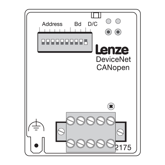
Node address L-C1850/2350 (^ 6-46) • Baud rate L-C1851/2351 (^ 6-47) The DIP switch on the front of the 2175 fieldbus module can be used for the following settings: • Controller address S1 - S6 • Baud rate S7 - S9 •... -
Page 24: Controller Address Setting
Show/Hide Bookmarks CANopen Commissioning Controller address setting Tip! Please ensure that the addresses are not the same when using several controllers. OPEN 1 2 3 4 5 6 7 8 9 10 ⋅ 2 ⋅ 2 ⋅ 2 ⋅ 2 ⋅... -
Page 25: Baud Rate Setting
Show/Hide Bookmarks CANopen Commissioning Baud rate setting Tip! Please ensure that the baud rate is the same for all controllers and the host. OPEN 1 2 3 4 5 6 7 8 9 10 Baud rate [kbit/s] 1000 Phone: 800.894.0412 - Fax: 888.723.4773 - Web: www.actechdrives.com - Email: info@actechdrives.com BA2175 EN 2.0... -
Page 26: Initial Switch-On
• earth fault 1. Switch on the controller and, if necessary, the external supply of the 2175 fieldbus module. – One of the operating status LEDs of the controller , pos. 3 must come on or blink. If (^ 4-1) this is not the case, see chapter ”... -
Page 27: Drive Enable Via 2175 Fieldbus Module
82XX / 1. Set the Lenze parameter Operating Mode (L-C0001) from 0 to 3 to enable the driva via the 2175 fieldbus module. The parameter can be set 8200 vector using the keypad or directly via CANopen. - Page 28 Show/Hide Bookmarks CANopen Commissioning Phone: 800.894.0412 - Fax: 888.723.4773 - Web: www.actechdrives.com - Email: info@actechdrives.com BA2175 EN 2.0...
- Page 29 Tab. 6-1 Division of parameter data and process data in different communication channels The following regulations for a communication protocol only describe what is related to Lenze controller networkds. Phone: 800.894.0412 - Fax: 888.723.4773 - Web: www.actechdrives.com - Email: info@actechdrives.com...
-
Page 30: Structure Of A Can Data Telegram
Show/Hide Bookmarks CANopen Parameter setting Structure of a CAN data telegram Control field CRC delimit. ACK delimit. CRC sequence Start RTR bit ACK slot User data 0 ... 8 byte Identifier • Network management • Parameter data 1 bit 11 bit 1 bit 6 bit 15 bit... -
Page 31: Network Management (Nmt)
Show/Hide Bookmarks CANopen Parameter setting 6.1.2 Network management (NMT) The telegram used for network management contains an identifier (see chapter 6.1.1) and the command which is part of the user data and consists of command byte and controller address. User data (2 byte) Identifier 1. - Page 32 Show/Hide Bookmarks CANopen Parameter setting 6.1.2.1 Node/ life guarding If you multiply guard time (chapter 6.4.1.8) and life time factor (chapter 6.4.1.9) the result is a time. This time must not be exceeded • when a request is sent to a slave •...
-
Page 33: Parameter Data Channel
Parameter setting Parameter data channel Note! • Lenze codes have a L in front of the code „ L-Cxxxx“ so that they cannot be mixed up with the CANopen index. – Example: ’L-C0001’ stands for Lenze code C0001. • Please obtain the value range for Lenze codes from the corresponding Operating Instructions (see ’Code list’). - Page 34 • Offset 0 addresses parameter set 1 with Lenze codes L-C0000 to L-C1999 the controller. This is the current • Offset 2000 addresses parameter set 2 with Lenze codes L-C2000 to L-C3999 parameter set Only the current parameter parameter set.
-
Page 35: Structure Of A Parameter Data Telegram
Low byte High byte Parameters and Lenze codes are selected with these two bytes according to the following formula: Index = 24575 − ( Lenze - code + 2000 ⋅ ( parameter set − 1)) Example Calculation Index low/high byte... -
Page 36: Examples
Depending on the data format (see ’Attribute list’ in the Manual) the parameter value needs 1 to 4 bytes. Tip! Lenze parameters are mainly FIX32 data (32 bit value with signal, decimal with four decimal codes, see the Attribute Table in the corresponding Manual). Integers are the result of a multiplication of a parameter value by 10000. - Page 37 Show/Hide Bookmarks CANopen Parameter setting The error code is displayed inverse to the direction of reading. Example: Error code 06 04 00 41 and representation of the error code: Direction of reading the error code 5th byte 6th byte 7th byte 8th byte Low word High word...
-
Page 38: Parameter Reading
Show/Hide Bookmarks CANopen Parameter setting 6.2.2 Examples 6.2.2.1 Parameter reading ° The heatsink temperature (43 C) C061 is to be read from the controller using address 5 and parameter channel 1. • Identifier calculation Identifier parameter channel 1 to controller = 1536 + controller address Identifier = 1536 + 5 = 1541... -
Page 39: Write Parameter
Show/Hide Bookmarks CANopen Parameter setting 6.2.3 Write parameter The acceleration time C0012 (parameter set 1) of the controller with address 1 is to be changed to 20 s via parameter channel 1. • Identifier calculation Identifier parameter channel 1 to controller = 1536 + controller address Identifier = 1536 + 1 = 1537... -
Page 40: Read Block Parameters
6.2.4 Read block parameters The software product code (code L-C0200) of a Lenze product is to be read from parameter set 1. The product code has 14 alphanumerical characters. They are transferred as block parameters. The transfer of block parameters uses the entire data width (2nd - 8th byte). -
Page 41: Process Data Channel
The function blocks can be combined and connected by the user himself. It is however safer to use the preconfiguration provided by Lenze which is stored in the controller. This preconfiguration (code C0005) determines the source (terminal, keyboard, fieldbus module) for frequency setpoint and control word. -
Page 42: Process Data Transfer
Show/Hide Bookmarks CANopen Parameter setting 6.3.2 Process data transfer Process data telegrams between host and controllers are distinguished as follows: • Process data telegrams to drive • Process data telegrams from drive Process data telegram to drive The process data telegram includes an indentifier which holds the address (93XX series). This telegram has a user data length of 8 byte (see example below). - Page 43 Show/Hide Bookmarks CANopen Parameter setting To ensure that the process data to the controller are accepted, a special telegram, the sync telegram, is required (see chapter 6.1.1). For cyclic data processing, the sync telegram must be generated accordingly. Process data synchronisation The sync telegra is the trigger point for •...
-
Page 44: Process-Data Assignments For 82Xx
Show/Hide Bookmarks CANopen Parameter setting 6.3.3 Process-data assignments for 82XX Process data telegram to controller User data length: 8 byte Byte 1 Byte 2 Byte 3 Byte 4 Byte 5 Byte 6 Byte 7 Byte 8 Control word Control word Setpoint Setpoint Identifier... - Page 45 Show/Hide Bookmarks CANopen Parameter setting Process data telegram from controller User data length: 8 byte Byte 1 Byte 2 Byte 3 Byte 4 Byte 5 Byte 6 Byte 7 Byte 8 Actual value Actual value Status word Status word Identifier L-C0150 L-C0150 L-C0050...
-
Page 46: Process-Data Assignment For 8200 Vector
Show/Hide Bookmarks CANopen Parameter setting 6.3.4 Process-data assignment for 8200 vector A change of code L-C0001 to 3 starts the preconfiguration of process data words in the controller (see chapter 6.3.1). . Tip! • Frequency and speed values are normalised with 24000 ≡ 480 Hz. Process data telegram to drive Byte 1 Byte 2... - Page 47 Show/Hide Bookmarks CANopen Parameter setting Process data telegram from drive Byte 1 Byte 2 Byte 3 Byte 4 Byte 5 Byte 6 Byte 7 Byte 8 Status word Status word AIF-OUT.W1 AIF-OUT.W1 AIF-OUT.W2 AIF-OUT.W2 Low byte High byte Low byte High byte Low byte High byte...
-
Page 48: Control Word For 82Xx And 8200 Vector
Show/Hide Bookmarks CANopen Parameter setting 6.3.4.1 Control word for 82XX and 8200 vector 8200vector AIF-CTRL AIF CTRL 820X 820X 821x,822x 821x,822x .Bxx Default setting: Default setting: C0001=3 if C0007 < 52 C0001=3 if C0007 > 51 00 = C0046 active 00 = C0046 active 00 = C0046 active 01 = JOG1 active in C0037... -
Page 49: Status Word For 82Xx And 8200 Vector
Show/Hide Bookmarks CANopen Parameter setting 6.3.4.2 Status word for 82XX and 8200 vector 820X 821x,822x 8200vector default setting Actual parameter set Actual parameter set DCTRL-PAR-B0 0 = Parameter set 1 or 3 active 0 = Parameter set 1 or 3 active 1 = Parameter set 2 or 4 active 1 = Parameter set 2 or 4 active IMP (pulse inhibit) -
Page 50: Process-Data Assignment For 93Xx
- described in the 93XX Manual - is used. The AIF-IN function block determines the input data of the controller as data interface for the 2175 fieldbus module. For more detailed information about the AIF-IN function block, see the 93XX Manual. -
Page 51: Control Word For 93Xx
Show/Hide Bookmarks CANopen Parameter setting 6.3.5.1 Control word for 93XX 9300 9300 Servo 9300 9300 9300 Vector Positioning Cam profiler controller C0005 1xx3 4xx3 5xx3 6xx3,7xx3 2xxx3 xxx3 1xxx, 2xxx, 4xx3 6xx3,7xx3 3xxx, 5xxx, 10xxx, 11xxx NSET-JOG*1 not assigned NSET-JOG*1 not assigned not assigned CSEL1-CAM*1... - Page 52 Show/Hide Bookmarks CANopen Parameter setting " #$ ˇ , * - " #$ ˇ ˇ . " #$ ˇ " ˛ " #$ ˇ #$ - * . # " #$ ˇ #$ - $ . * . # " #$ ˇ , * - "...
- Page 53 - described in the 93XX Manual - is used. The AIF-OUT function block determines the controller output data as data interface for the 2175 fieldbus module. For more detailed information about the AIF-OUT function block, see the 93XX Manual .
-
Page 54: Status Word For 93Xx
Show/Hide Bookmarks CANopen Parameter setting 6.3.5.2 Status word for 93XX 9300 Servo Servo Servo cam vector positioning profiler controller C0005 1xx3 4xx3 5xx3 6xx3,7xx3 2xxx3 1xxx3 xxx, 2xxx, 4xxx 6xxx, 7xxx, 3xxx, 5xxx, 8xxx, 9xxx 10xxx, 11xxx DCTRL-PAR1-0 DCTRL-PAR1-0 DCTRL-PAR1-0 DCTRL-PAR1-0 not assigned CERR1-ERR DCTRL-PAR1-0 DCTRL-PAR1-0 DCTRL-PAR1-0 DCTRL-IMP... - Page 55 Show/Hide Bookmarks CANopen Parameter setting * # # * # # " ˜ 0 " ˜ 0 ! " #$ ˇ 3 - ! " #$ ˇ 3 - * # # * # # " ˜ 0 " ˜ 0 * # # ˜...
-
Page 56: Implemented Canopen Objects
Instructions are defined according to the “ CiA Draft Standard 301/Version 4.01” . All CANopen objects can also be mapped by Lenze codes. The section “CANopen relation” describes how a change of CANopen objects influences Lenze codes. - Page 57 Show/Hide Bookmarks CANopen Parameter setting Index [hex] Subindex Name Data type Authorisation [hex] 1402 1402 PDO comm. PDO comm. Receive PDO3* parameter Number of entries COB-ID used by PDO Transmission type 1600 1600 Receive PDO1 mapping parameter PDO mapping PDO mapping Number of mapped objects in PDOs PDO mapping 1 PDO mapping 2...
-
Page 58: Description Of Implemented Objects
Show/Hide Bookmarks CANopen Parameter setting 6.4.1 Description of implemented objects 6.4.1.1 1000 : Device type Reading of the device type and its functionality Index [ Subindex Name Data type Authorisation 1000 Device type Bit assignment in telegram data 5th byte 6th byte 7th byte 8th byte... - Page 59 (11 - 28)* The extended identifier (29 bit) is not supported for the 2175 fieldbus Any of these bits must be 0 The extended identifier (29 bit) is not supported for the 2175 fieldbus. Any of these bits must be 0.
- Page 60 Show/Hide Bookmarks CANopen Parameter setting 6.4.1.7 100A : Manufacturer’s software version Controller and module software version Index [hex] Subindex Name Data type Authorisation 100A Manufacturer software version Vis. string const {11 characters} 6.4.1.8 100C : Guard time Monitoring time Index [hex] Subindex Name Data type Authorisation...
- Page 61 Reading of memory functions of Value 0: No saving communication parameters (objects Value 1: Saving on command of the 2175 fieldbus module) • Value 2: Automatic saving This function is not This function is not Value 3: Automatic saving and...
- Page 62 (11 - 28)* The extended identifier (29 bit) is not supported for the 2175 fieldbus Any of these bits must be 0 The extended identifier (29 bit) is not supported for the 2175 fieldbus. Any of these bits must be 0.
- Page 63 0 - 10 Identifier (see chapter 6.1.1) (11 - 28)* The extended identifier (29 bit) is not supported for the 2175 fieldbus. Any The extended identifier (29 bit) is not supported for the 2175 fieldbus. Any of these bits must be 0.
- Page 64 10 - 0 (LSB) Contains identifier (basic + controller address) (11 - 28)* The extended identifier (29 bit) is not supported for the 2175 fieldbus. Every bit must become 0! The extended identifier (29 bit) is not supported for the 2175 fieldbus.
- Page 65 Show/Hide Bookmarks CANopen Parameter setting 6.4.1.18 1402 : Receive PDO3* communication parameter Receipt of PDO 3 communication parameters Tip! *) Object not available for 82XX, 8200 vector and 93XX controllers. Index [hex] Subindex Name Data type Rights Explanation PDO comm. ro Subindex 0: Max.
- Page 66 Show/Hide Bookmarks CANopen Parameter setting 6.4.1.19 1600 : Receive PDO1 mapping parameter With this object, parameter data can be received as PDO1. Tip! At present this functionality is not available. Depending on the subindex, the following values are returned when reading the object: Subind.
- Page 67 Show/Hide Bookmarks CANopen Parameter setting 6.4.1.21 1602 : Receive PDO3* mapping parameter With this object, parameter data can be received as PDO3. Tip! At present this functionality is not available. Depending on the subindex, the following values are returned when reading the object: Subind.
- Page 68 Show/Hide Bookmarks CANopen Parameter setting 6.4.1.22 1800 : Transmit PDO1 parameter Sending of process data Index [hex] Subindex Name Data type Authoris Explanation ation Number of supported subindexes Max. supported subindex = 2 1800 1800 PDO identifier PDO Comm. PDO Comm. Identifier setting for this PDO (180 + node ID) Transfer type...
-
Page 69: Parameter Setting
Show/Hide Bookmarks CANopen Parameter setting 6.4.1.25 1A00 : Transmit PDO1 mapping parameter With this object, parameter data can be sent as PDO1. Tip! At present this functionality is not available. Depending on the subindex, the following values are returned when reading the object: Subind. - Page 70 Show/Hide Bookmarks CANopen Parameter setting 6.4.1.27 1A02 : Transmit PDO3* mapping parameter With this object, parameter data can be sent as PDO3. Tip! At present this functionality is not available. Depending on the subindex, the following values are returned when reading the object: Subind.
-
Page 71: Communication-Relevant Lenze Codes
These (Lenze) codes are exchanged between master and 2175 fieldbus module as part of a telegram and via a CAN bus. Depending on the Lenze inverter, the following codes are available for communication via CAN bus: •... - Page 72 = 22722 0 = Addressing to CANopen FIX32 CAN-INx/CAN-OUTx addressing 1 = Addressing to L-C1854/L-C2354 /1 ... /3 2 = Addressing to LENZE system bus 3 = Addressing to CANopen index 14Xx /18XX L-C1854 /1 ... /2 58C1 = 22721...
- Page 73 56CE = 22222 0 = Addressing to CANopen FIX32 CAN-INx/CAN-OUTx addressing 1 = Addressing to L-C1854/L-C2354 /1 ... /3 2 = Addressing to LENZE system bus 3 = Addressing to CANopen index 14Xx /18XX L-C2354 56CD = 22221 1663 FIX32...
-
Page 74: Description Of Communication-Relevant Lenze Codes
This code is only effective if the DIP switches S1-S6 have been switched OFF before mains switching. A node address modification will only become active after power-on of the 2175 module or sending of the network management command Reset_node or Reset_communication via the CAN bus. -
Page 75: L-C1851/L-C2351: Baud Rate
This code is only effective if the DIP switches S1-S6 have been switched OFF before mains switching. A baud rate modification will only become active after power-on of the 2175 module or sending of the network management command Reset_node or Reset_communication via the CAN bus. -
Page 76: L-C1853/L-C2353: Can-Inx/Can-Outx Addressing
L-C1853 0 = Addressing to CANopen 58C2 = 22722 FIX32 1 = Addressing to L-C1854/L-C2354 /1 CAN-IN1/OUT1 2 = Addressing to LENZE system bus 2 = Addressing to LENZE system bus /2 CAN IN2/OUT2 /2 CAN-IN2/OUT2 L-C2353 56CE = 22222... -
Page 77: L-C1854/L-C2354: Selective Can-In/Can-Out Addressing
Show/Hide Bookmarks CANopen Parameter setting 6.5.2.7 L-C1854/ L-C2354: Selective CAN-IN/ CAN-OUT addressing Possible settings Code Subcode Index Lenze Selection Data type /1 CAN-IN1 /1: 129 1663 FIX32 L-C1854 58C1 = 22721 /2 CAN-OUT1 /2: 1 /3* CAN-IN2 /3 CAN IN2... -
Page 78: L-C1856/L-2356: Boot-Up And Cycle Times
“ communication cycle period” corresponds to the settings under codes µ L-C1856/5 and L-C2356/5 (Zeitbasis: µ Since the data processing rate of the 2175 module is 1000 s,the input via CANopen index 1006 µ is an integer multiple of 1000 s gerundet und unter L-C1856/5 oder L-C2356/5 (abhängig vom... -
Page 79: L-C1857/L-C2357: Monitoring Time
Show/Hide Bookmarks CANopen Parameter setting 6.5.2.10 L-C1857/ L-C2357: Monitoring time Possible settings Code Subcode Index Lenze Selection Data type L-C1857 3000 ms 0 [1 ms] 65535 FIX32 58BE = 22718 /1 CAN-IN1 /2 CAN-IN2 /3 CAN IN3 /3 CAN-IN3 L-C2357... -
Page 80: L-C1860: Display Of Current Dip-Switch Position
Parameter setting 6.5.2.12 L-C1860: Display of current DIP-switch position Possible settings Code Subcode Index Lenze Selection Data type L-C1860 58BB = 22715 1023 U16 By indicating the current DIP-switch position it is made easy to find out whether the switch positions for address, baud rate and the communication profile setting have been changed since the last initialisation. - Page 81 Show/Hide Bookmarks CANopen Parameter setting Possible settings Code Code Index Index Subcode Lenze Selection Data type L-C1873 240 FIX32 58AE = 22702 /1 CAN-IN1 /1 CAN IN1 /2* CAN-IN2 L-C2373 56BA = 22202 FIX32 /3* CAN-IN3 *) not effective when using 82XX, 8200 vector and 93XX controllers Example: Selection n = 23.
- Page 82 This code contains a selection which indicates when CAN-OUT1 .. CAN-OUT3 PDO are to be sent. The selection can be made for every output PDO by subdivision into subcodes. Possible settings Code Code Index Index Subcode Lenze Selection Data type L-C1875 58AC = 22700 /1: 0 3 FIX32...
- Page 83 L-C2378 and achieve that the CAN-OUT object will not be sent when a bit is changed. 6.5.2.18 L-C1876/ L-C2376: CAN-OUT1 masks This mask is used to skip one or several bits of the CAN-OUT1 output PDO. Possible settings Code Subcode Index Lenze Selection Data type L-C1876 /1 CAN-OUT1.W1 65535 65535 FIX32 58AB = 22699 /2 CAN-OUT1.W2...
-
Page 84: L-C2120: Aif Control Byte
“ life time factor” saves a factor. The monitoring time (time in which the master sends a certain telegram to the slave/2175 IB) results from multiplying the two indexes. If one of the indexes is set to zero, the monitoring time is zero too and thus deactivated. The slave sends a telegram with its current NMT status to the master. -
Page 85: L-C2121: Aif Status Byte
Parameter setting The AIF control byte is used to read the codes saved in a 9300 servo PLC by the 2175 fieldbus module. This process can be started by writing a value which is indicated in the table in the AIF control byte. -
Page 86: Notes To Be Observed For Paramater Setting
The TRIP reset function is activated by inhibiting the controller and enabling it again under C040 or C0135. The TRIP reset function initializes the 8200 inverter and the 2175 fieldbus module. Therefore the TRIP reset command is not acknowledged for the master. -
Page 87: Servo Plc
Pre-operational Warning Internally assigned The control byte is used to send messages and commands from the controller to the 2175 fieldbus module. The control byte can be accessed via code C2120. The commands are defined as numbers. Some of the command numbers apply to all fieldbus modules, others only apply to certain modules. - Page 88 Show/Hide Bookmarks CANopen Parameter setting Phone: 800.894.0412 - Fax: 888.723.4773 - Web: www.actechdrives.com - Email: info@actechdrives.com 6-60 BA2175 EN 2.0...
-
Page 89: Troubleshooting And Fault Elimination
Show/Hide Bookmarks CANopen Troubleshooting and fault elimination Troubleshooting and fault elimination No communication with the controller Possible causes Diagnostics Remedy Is the controller switched on? The operation status LED of the basic Supply controller with voltage (see Operating Instructions for the basic unit) unit must be on ^ 4-1 Point 3. - Page 90 Show/Hide Bookmarks CANopen Troubleshooting and fault elimination Phone: 800.894.0412 - Fax: 888.723.4773 - Web: www.actechdrives.com - Email: info@actechdrives.com BA2175 EN 2.0...
-
Page 91: Table Of Keywords
CAN bus system, Assembly, 4-5 Control word, 6-20 Code numbers, Access via the fieldbus module, 6-5 Status word, 6-21 Code numbers / index, Conversion, 6-5 82XX, Status word, 6-21 Codes, Lenze, 6-5 Commissioning, 5-1 82XX Communication medium, 3-2 Control word, 6-20 Communication profile, 5-1... - Page 92 Layout, 2-2 Labelling, Controller, 1-2 Other notes, 2-2 Warning of damage to material, 2-2 Legal regulations, 1-2 Warning of damage to persons, 2-2 Lenze codes, 6-5 Operating Instructions, 1-1 Liability, 1-2 Setpoint source, 6-13 Manufacturer, 1-2 Technical data, 3-1 Network management (NMT), 6-3...
-
Page 93: Technical Data
The units are directly connected to the network. This means reduced costs for installation, commissioning, maintenance, tests and upgrading of the system. The 2175 fieldbus module with the communication profile DeviceNet is a ’ONLY-SERVER’ module of group 2. Features •... -
Page 94: General Data And Application Conditions
0 V AC No electrical isolation Pollution degree VDE0110, part 2, pollution degree 2 Dimensions DeviceNet CANopen Fig. 9-1 Dimensions: 2175 fieldbus module (all dimensions in mm) Phone: 800.894.0412 - Fax: 888.723.4773 - Web: www.actechdrives.com - Email: info@actechdrives.com BA2175 EN 2.0... -
Page 95: Communication Times
Show/Hide Bookmarks DeviceNet Technical data 9.5.1 Communication times Note! The CAN bus communication times depend on the following: • Processing time in the controller • Baud rate • Data priority • Bus load More information about bus access control can be obtained from corresponding literature specialised on Controller Area Networks. - Page 96 Show/Hide Bookmarks DeviceNet Technical data The individual telegram times are: Telegram Processing time PE-inhibit = 0 PE-inhibit = 1 Parameters 62...140 ms 62...70 ms Change of a process data value 27...105 ms 27...35 ms to controller (*) Change of both process data values to controller * 62...140 ms 4...70 ms...
- Page 97 Show/Hide Bookmarks DeviceNet Technical data 9.5.1.2 Telegram time Telegram times depend on baud rate and telegram length: Data length [byte] Baud rate [kbit/s] Baud rate [kbit/s] 5.44 7.36 13.12 2.72 3.68 6.56 1.09 1.47 2.62 0.44 0.59 1.05 0.22 0.29 0.52 0.11 0.15...
- Page 98 Show/Hide Bookmarks DeviceNet Technical data Phone: 800.894.0412 - Fax: 888.723.4773 - Web: www.actechdrives.com - Email: info@actechdrives.com BA2175 EN 2.0...
-
Page 99: Installation
Components of the fieldbus module Pos. Designation Meaning Notes 2175 fieldbus module is not supplied with voltage; controller or external voltage supply is switched off. St t Status of the f th BLINKING 2175 fieldbus module is supplied with voltage but is not connected to the controller (controller is controller switched off, in initialization or not available). -
Page 100: Mechanical Installation
Show/Hide Bookmarks DeviceNet Installation 10.2 Mechanical installation • Plug the fieldbus module onto the controller (here: 8200 vector) • Tighten the fixing screw Pos. 4) (^ 10-1) Phone: 800.894.0412 - Fax: 888.723.4773 - Web: www.actechdrives.com - Email: info@actechdrives.com 10-2 BA2175 EN 2.0... -
Page 101: Electrical Installation
10.3.2 Assignment of the plug/ socket connector The 2175 fieldbus module is connected to the bus through a 5 pole plug/socket connector. The assignment of the plug/socket connector and the cable colour used according to the DeviceNet Specification is listed in the table. -
Page 102: Wiring To A Host
Controllers with an extended AIF interface (front of the 8200 vector) can be internally supplied. The part of the drawing highlighted in grey shows the jumper position. With Lenze setting, the fieldbus module is not internally supplied. For internal voltage supply, put the jumper in the position indicated below. - Page 103 The following diagram shows a network: By means of this network 8200 vector controllers with attached 2175 fieldbus modules 0 can communicate with the DeviceNet master. For easy configuration of the fieldbus modules a PC with “ DeviceNet Manager” software 1 can be used.
- Page 104 Show/Hide Bookmarks DeviceNet Installation 10.4 Features of the “thick” cable (according to DeviceNet Specification) General features General features Two shielded pairs Common axis with drain wire in center. Total shielding 65% coverage 36 AWG or 0.12mm Cu braid (individually tinned) Drain wire #18 copper min.;...
- Page 105 Show/Hide Bookmarks DeviceNet Installation 10.5 Features of the “ thin” cable (according to DeviceNet Specification) General features General features Two shielded pairs Common axis with drain wire in center. Total shielding 65% coverage 36 AWG or 0.12mm Cu braid (individually tinned) Drain wire #22 copper min.;...
- Page 106 Show/Hide Bookmarks DeviceNet Installation Phone: 800.894.0412 - Fax: 888.723.4773 - Web: www.actechdrives.com - Email: info@actechdrives.com 10-8 BA2175 EN 2.0...
- Page 107 Please see the descriptions for • L-C1850/2350 node address • L-C1851/2351 baud rate The DIP switch on the front of the 2175 fieldbus module can be used for the following settings: • Controller address S1 - S6 • Baud rate S7 - S9 •...
-
Page 108: Controller Address Setting
Show/Hide Bookmarks DeviceNet Commissioning 11.2 Controller address setting Note! Please ensure that the addresses are not the same when using several controllers. OPEN 1 2 3 4 5 6 7 8 9 10 ⋅ 2 ⋅ 2 ⋅ 2 ⋅ 2 ⋅... - Page 109 • earth fault 1. Switch on the controller and, if necessary, the external supply of the 2175 fieldbus module. – A controller status LED ( , pos. 3 ) must now be on or blinking. If this is not the case, (^ 10-1) see chapter ”...
- Page 110 Drive enable via 2175 fieldbus module 82XX / 1. Set the Lenze parameter Operating Mode (L-C0001) from 0 to 3 to enable the drive via the 2175 fieldbus module. The parameter can be set 8200 vector using the keypad or directly via CAN.
-
Page 111: General Information
The heartbeat interval is set by means of the cyclic timer. NOTE: The default message type for 2175 DeviceNet modules is the I/O polled message. Other message types can be enabled using the DeviceNet Manager. - Page 112 The product code (attribute 3) of the identity class contains “ 01” in the HIGH byte for the 2175 fieldbus module. The LOW byte contains the number of process data words. The information given in the identity class are unambiguous for every module. Attribute 6 contains the default setting for every module.
- Page 113 Show/Hide Bookmarks DeviceNet Parameter setting Connection class (class 5) (GET/ ---) The connection class determines process and parameter data features. Attribute 1 Attribute 2 Attribute 3 Attribute 4 Attribute 5 Attribute 6 Attribute 7 Attribute 8 Instance 1 Instance type Instance type SDO length (see TIP) Produced...
- Page 114 Show/Hide Bookmarks DeviceNet Parameter setting Vendor-specific class (class 100) (GET/ SET) Instance 1 Byte Byte • Attribute 1: Parameter data Request Response Code Low Code Low Code High Code High Subcode Subcode • Reserve Status Byte value = 0: No errors •...
- Page 115 Show/Hide Bookmarks DeviceNet Parameter setting Vendor-specific class (class 101) (GET/ SET) Instance 1 • Attribute 1: Process data monitoring code (2 byte) 0: No response (default) 1: Controller inhibit 2: Quick stop This setting is saved as non-volatile value in the EEPROM. Vendor-specific class (class 102) (GET/ SET) Instance 1 •...
- Page 116 12.1 Communication-relevant Lenze codes Tip! If the 2175 module is plugged onto a different controller during operation, an undefined operating status might occur. The behaviour of servo inverters and frequency inverters is determined by their parameters. Lenze controllers can be parameterised by codes. These (Lenze) codes are exchanged between master and 2175 fieldbus module as part of a telegram and via a CAN bus.
- Page 117 The TRIP reset function is activated by inhibiting the controller and enabling it again under C040 or C0135. The TRIP reset function initializes the 8200 inverter and the 2175 fieldbus module. Therefore the TRIP reset command is not acknowledged for the master.
- Page 118 Show/Hide Bookmarks DeviceNet Parameter setting Phone: 800.894.0412 - Fax: 888.723.4773 - Web: www.actechdrives.com - Email: info@actechdrives.com 12-8 BA2175 EN 2.0...
- Page 119 Show/Hide Bookmarks DeviceNet Troubleshooting and fault elimination Troubleshooting and fault elimination 13.1 No communication with the controller. Possible causes Diagnostics Remedy Is the controller switched on? The operation status LED of the basic Supply controller with voltage (see Operating Instructions for the basic unit) unit must be on ^ 10-1 Point 3.
- Page 120 Show/Hide Bookmarks DeviceNet Troubleshooting and fault elimination Phone: 800.894.0412 - Fax: 888.723.4773 - Web: www.actechdrives.com - Email: info@actechdrives.com 13-2 BA2175 EN 2.0...
-
Page 121: Commissioning
Setpoint selection via process data channel of the 2175 fieldbus module: C0001 = 3 Controller type: 9300 servo inverter, node 34 Setpoint selection via process data channel of the 2175 fieldbus module C0005 = xxx3 RS232 interface module type, 1770-KFD Parameter setting for communication via DeviceNet: ... -
Page 122: Integration Of Lenze-Eds Files Into "Rsnetworx"
(see example “ RSNetWorx” , Allen Bradley). The file name includes the fieldbus (’2175’), two letters (’ib’, interface module) and a two-digit number which indicates the number of supported process data words (16 bit/word). - Page 123 3. Select Register an EDS file 2175DeN053 4. Select Register a directory of EDS files A group of LENZE-EDS files and their path ( Browse ) must be registered. 2175DeN054 5. Wizard finds the LENZE-EDS files (” 2175IBxx.EDS” ) and indicates the test result.
- Page 124 7. The registration query will be completed when pressing Complete . 2175DeN057 All inserted data are now available for the hardware catalog. The path is: DeviceNet/Vendor/Lenze GmbH&CoKG/Generic Device 2175DeN059 The process data length depends on the controller used. Select according to the controller: •...
-
Page 125: Communication Between Pc And Devicenet Via "Rslinx"
Show/Hide Bookmarks DeviceNet Appendix 14.1.2 Communication between PC and DeviceNet via “ RSLinx” 1. Start “ RSLinx” 2. Select Communication WConfigure Drivers 2175DeN086 3. Select DeviceNet Drivers . Confirm with Add new. 2175DeN060 4. Select Interface 1770-KFD . Confirm with Select . 2175DeN061 5. - Page 126 The “ RSLinx” software tool must run in the background to coordinate PC and KFD box. • If node addresses are marked with question marks, Lenze components cannot be identified because the corresponding EDS files are missing. Chapter 14.1.1 describes how to proceed.
-
Page 127: Online Connection Between Devicenet And "Rsnetworx"
Show/Hide Bookmarks DeviceNet Appendix 14.1.3 Online connection between DeviceNet and “ RSNetWorx“ 1. Select NetworkWOnline. 2175DeN065 The menu for scanning DeviceNet will be opened. 1770-KFD-1 lists all bus nodes. 2. Select Autobrowse or Refresh. Confirm with OK. The bus is searched for connected devices. 2175DeN066/067 The components found are indicated as follows: 2175DeN068... - Page 128 Show/Hide Bookmarks DeviceNet Appendix Processing assignment (scanner properties) Set the I/O address assignment between CPU and DeviceNet devices under Properties of the DeviceNet scanner using “ RSNetWorx” . 1. General scanner data are indicated when the scanner symbol is double clicked. 2175DeN069 2.
- Page 129 Show/Hide Bookmarks DeviceNet Appendix 3. Register card Scan list Under Available devices you will find a list of all components which can be shifted into the Scan list . Use Automap on add (arrow) to automatically enter all devices into the Scan list . The DeviceNet devices listed here will be processed by the scanner.
- Page 130 Show/Hide Bookmarks DeviceNet Appendix 4. Register card Input / register card Output 2175DeN074/75 • Use Input to enter the peripheral input address of every device. – The function Automap automatically assigns the input address in the DeviceNet scanner. Select Unmap to remove this assignment. –...
- Page 131 Show/Hide Bookmarks DeviceNet Appendix Processing assignment (DeviceNet slave properties) 1. Select a controller (right mouse key) 2. Select Properties 2175DeN078 • Register card General Here you will find general data of the EDS file for a certain device. 2175DeN079 • Register card Parameters –...
- Page 132 Show/Hide Bookmarks DeviceNet Appendix • Register card I/ O defaults Tip! Modifications cannot be made since the communication profile has been defined in the scanner. 2175DeN081 • Register card EDS file This card shows the identification data of and EDS file. 2175DeN082 Phone: 800.894.0412 - Fax: 888.723.4773 - Web: www.actechdrives.com - Email: info@actechdrives.com 14-12...
- Page 133 Value (get single attribute), value = 10 (set single attribute) • Class (always with Lenze controllers) • Instance 1 (always with Lenze controllers) • Attribute 1 (always with Lenze controllers) • Data sent to the device 000C 0000 • Data received from the device...
-
Page 134: Set Scanner Status
Show/Hide Bookmarks DeviceNet Appendix 14.1.4 Set scanner status The scanner is equipped with two status LEDs and a 7-segment display (3 digits): • LED MODULE: Status display for the scanner module (should be green) • LED NET: Status disply for the network (DeviceNet) (should be green) •... -
Page 135: Communication Between Pc And Plc
Show/Hide Bookmarks DeviceNet Appendix 14.1.5 Communication between PC and PLC PC and PLC communicate via the RS232 interface of the PC and the CPU of the PLC (ALLEN-BRADLEY) (see Tab. 14-1, Communication is controlled by the “ RSLinx” program. It must be configured and activated before online programming starts. - Page 136 Show/Hide Bookmarks DeviceNet Appendix 5. The next window will be displayed. Close the window with Close . 2175DeN089 With Autobrowse you can look at the communication in the start window of “ RSLinx” : • Address 00: PC • Address 01: SLC5/04 2175DeN065 Note! Select View/ Options/ Service to determine whether “...
-
Page 137: Starting Of The "Rslogix 500 English" Plc Program
Show/Hide Bookmarks DeviceNet Appendix 14.1.6 Starting of the “ RSLogix 500 English” PLC program 1. Select File new to create a new project. 2. Select “ SLC5/04 CPU” (Rack with four slots; exact name on CPU flap with “ 1747-L541” ) 2175DeN092 The window changes to the current project. - Page 138 Show/Hide Bookmarks DeviceNet Appendix 4. Select Who Active. The active driver will be selected. 2175DeN095 5. Select SLC 5/04 . Confirm with OK. 2175DeN096 6. Select Read IO config to automatically start search and ’fill’ the rack. The individual slots are equipped with the components shown in Tab. 14-1 2175DeN097 The I/O configuration is completed.
-
Page 139: Control Program Programming
14.2 Control program programming The SLC programming is explained by means of the example named “ 82VEC2175PZD_Para.RSS” . Note! This example is also available on the internet at Lenze website Path Service W Downloads W DeviceNet 14.2.1 Hardware addressing DeviceNet is configured with the following node addresses •... -
Page 140: Explicit Messages
Show/Hide Bookmarks DeviceNet Appendix 14.2.2 Explicit messages “ Explicit Messages” can transfer parameter data between controllers and the SLC-CPU via the DeviceNet parameter channel. Data between the “ SLC5/04-CPU” , DeviceNet scanner “ 1747” and the DeviceNet device is transferred via “ module files” : Module file DeviceNet data direction Data path •... -
Page 141: Program Components
Show/Hide Bookmarks DeviceNet Appendix 14.3 Program components 2175DeN098 Program component nesting: LAD 31 LAD 30 LAD 2 LAD 3 LENZE_PIO LENZE_MAIN Main DNET_MAIN (analog setpoint) LAD 33 EXP_BTW (writing of an LAD 32 explicit LENZE_EXP message) (preparation for an LAD 34 explicit EXP_BTR message) -
Page 142: Lad 2-Main
Show/Hide Bookmarks DeviceNet Appendix 14.3.1 LAD 2-Main • Program basis • The program is in first position of the processing table 2175DeN101 Programmed marker bits: • Rung 0000 = Zero marker bit always defined as zero • Rung 0001 = One marker bit always defined as one •... -
Page 143: Lad 3 - Dnet_Main
Show/Hide Bookmarks DeviceNet Appendix 14.3.2 LAD 3 - DNET_MAIN The 1747 scanner is activated here. Two bits of a DeviceNet device are activated via digital inputs. 2175DeN102 • Rung 0000 = Scanner enable via the ” One marker bit” (generated in LAD 2). The scanner is always in “... -
Page 144: Lad30 - Lenze_Main
Show/Hide Bookmarks DeviceNet Appendix 14.3.3 LAD30 - LENZE_MAIN Jump to routines 31 and 32 2175DeN103 14.3.4 LAD31 - LENZE_PIO Sending of the controller setpoint 2175DeN104 The example describes the writing of the speed setpoint to the 8200 vector frequency inverter. dec ≡... -
Page 145: Lad32 - Lenze_Exp
Show/Hide Bookmarks DeviceNet Appendix 14.3.5 LAD32 - LENZE_EXP Preparations for explicit messages 2175DeN105 • Rung 0000: Data area N10:0 is set zero. This data area is used to save input data of explicit messages. Here the order is activated via a digital input. •... -
Page 146: Lad33 - Expl_Btw
Service + Mac ID Service = 0E = Get single attribute + Mac ID = 1C = 28 node address N9:3 0064 Class Class = 0064 = 100 with Lenze controllers N9:4 0001 Instance Instance = 0001 with Lenze controllers... - Page 147 Show/Hide Bookmarks DeviceNet Appendix 2175DeN108 Fig. 14-1 Data display in “ Data File N9” The order response is read from the subroutine LAD 34 (see (^ 14-28) Phone: 800.894.0412 - Fax: 888.723.4773 - Web: www.actechdrives.com - Email: info@actechdrives.com 14-27 BA2175 EN 2.0...
-
Page 148: Lad34 - Expl_Btr
Show/Hide Bookmarks DeviceNet Appendix 14.3.7 LAD34 - EXPL_BTR The scanner content is read. 2175DeN107 Scanner status bit 15 indicates that a response is available in scanner area M1:1. The scanner status bit activates the copy command and sets a marker bit. The marker bit activates the scanner reset to ensure the next order. -
Page 149: Baud Rate Setting
Show/Hide Bookmarks DeviceNet Table of keywords Table of keywords 8200 inverter series, 12-7 Fault elimination, 13-1 Fieldbus module, Connections, 10-3 Address setting, 11-2 Appendix, 14-1 Application, as directed, 1-2 Application as directed, 1-2 Installation Application conditions, 9-2 Mechanical, 10-2 Assignment of the plug/socket connector, 10-3 Wiring to a host, 10-4 Items supplied, 1-1 Basic insulation, 10-4... - Page 150 Show/Hide Bookmarks DeviceNet Table of keywords Safety information, 2-1 Layout, 2-2 Voltage supply, 10-4 Other notes, 2-2 Warning of damage to material, 2-2 Warning of damage to persons, 2-2 Voltage supply, external, 10-3 Operating Instructions, 1-1 Technical data, 9-1 Technicaldata Dimensions, 9-2 General data/Application conditions, 9-2 Telegram time, 9-5...
- Page 151 Show/Hide Bookmarks DeviceNet Table of keywords Phone: 800.894.0412 - Fax: 888.723.4773 - Web: www.actechdrives.com - Email: info@actechdrives.com 15-3 BA2175 EN 2.0...
- Page 152 Show/Hide Bookmarks DeviceNet Table of keywords Phone: 800.894.0412 - Fax: 888.723.4773 - Web: www.actechdrives.com - Email: info@actechdrives.com 15-4 BA2175 EN 2.0...
Need help?
Do you have a question about the 2175 and is the answer not in the manual?
Questions and answers