Table of Contents
Advertisement
Quick Links
BE SURE POWER IS DISCONNECTED PRIOR TO INSTALLATION!!
READ THESE INSTRUCTIONS ENTIRELY BEFORE INSTALLATION.
CONNECTIONS
1. Using the four corner tabs OR the DIN rail mounting bracket, mount the Model 77C directly
above or below the magnetic contactor. To use the DIN rail bracket, hook the top clip first,
then apply downward pressure until the lower clip snaps onto the rail.
2. Insert the motor conductors through the round holes marked A and B. Terminate the
conductors at the line or load side of the magnetic contactor. For motors with full load
amps less than 25 Amps, loop the conductors through the holes marked A and B according
to Table 1. The rectangular holes are provided for wire looping (see Figure 1).
3. For motors with full load current above 90 A, an external current transformer (CT) must
be used (see Figure 2). SymCom recommends using CTs with terminals for installation
convenience. When using an external CT, five passes must be made through the holes in
the Model 77C.
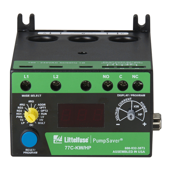
4. Connect the single-phase power from the line side of the contactor to L1 and L2. First insert
a#12 - #18 AWG copper wire into the top of the terminal marked L1 and tighten the screw on
the front of the overload relay. Connect the other end of the wire to the line side of the
contactor. Repeat these steps for L2 (see Figure 1).
5. Connect the output relay to the circuitry to be controlled (see Figure 1). To control a motor,
connect the NO (normally open) contact in series with the magnetic coil of the motor starter
as shown. To sound an alarm, connect the NC (normally closed) contact in series with the
alarm (not shown).
FOLLOW NATIONAL, STATE AND LOCAL CODES!
INSTALLATION INSTRUCTIONS FOR
SYMCOM'S
MODEL 77C
ELECTRONIC OVERLOAD RELAY
2880 North Plaza Drive, Rapid City, SD 57702
(800) 843-8848 · (605) 348-5580
www.symcom.com
Advertisement
Table of Contents

Subscribe to Our Youtube Channel
Summary of Contents for Motor Saver SymCom 77C
- Page 1 INSTALLATION INSTRUCTIONS FOR SYMCOM’S MODEL 77C ELECTRONIC OVERLOAD RELAY BE SURE POWER IS DISCONNECTED PRIOR TO INSTALLATION!! FOLLOW NATIONAL, STATE AND LOCAL CODES! READ THESE INSTRUCTIONS ENTIRELY BEFORE INSTALLATION. CONNECTIONS 1. Using the four corner tabs OR the DIN rail mounting bracket, mount the Model 77C directly above or below the magnetic contactor.
- Page 2 Recommended OC Range UC Range # of Passes through MULT (CT Full Load Amps (Amps) (Amps) each Window Ratio) 2-2.5 2-10 0, 1-9.8 2.5-3 2.22-11.1 0, 1.11-10.8 3-3.5 2.5-12.5 0, 1.25-12.2 3.5-4 2.85-14.2 0, 1.42-14 3.33-16.6 0, 1.66-16.3 4-20 0, 2-19.6 5-25 0, 2.5-24.5 8-12...
- Page 3 Figure 1: Typical Wiring Diagram Figure 2: External CT wiring diagram 10/05...
- Page 4 SUGGESTED SETTINGS Consult the motor manufacturer for recommended settings. Refer to the PROGRAMMING EXAMPLES section for additional assistance. LV/HV- The recommended settings for LV (low voltage) and HV (high voltage) depend on many factors such as motor usage, motor size, environmental factors and tolerance of the motor.
- Page 5 #RU- #RU is the number of successive restart attempts allowed after an undercurrent fault before the overload relay requires manual resetting. A setting of 0 is manual reset and a setting of A is continuously automatic reset. #RO- #RO is the number of successive restart attempts allowed after an overcurrent fault.
- Page 6 Trip Class Application Description Small fractional horsepower motors where acceleration times are almost instantaneous or where extremely quick trip times are required (Fast Trip) Hermetic refrigerant motors, compressors, submersible pumps and general-purpose motors that reach rated speed in less than 4 seconds.
- Page 7 PROGRAMMING EXAMPLE Motor to be protected: single-phase, 230V, 10hp raw material transfer auger. This auger moves material from a large bulk delivery pit to the production area main storage hopper. The motor has a full load amperage rating of 50 Amps and a maximum service factor of 57 Amps. Use the following calculations and reasoning to determine the appropriate settings for this application.
- Page 8 TROUBLESHOOTING Problem Solution Unit will not start - display The incoming voltage is not within the limits programmed in the HV alternates “HI” or “Lo” with the and LV settings. Adjust the DISPLAY/PROGRAM dial to read the DISPLAY/PROGRAM dial incoming line voltage value. Correct the incoming power problem parameter value and check programmed limits to verify they are correct.
- Page 9 MODEL 77C SPECIFICATIONS Electrical Input Voltage 100-240VAC, single-phase Frequency 50/60 Hz 2-25A (loops required) Motor Full Load Amp Range 25-90A (direct) 80-800A (external CTs) Short Circuit 100kA per UL, 10kA per CSA Power Consumption 10 Watts (max.) Pilot duty rating: 480VA @ 240VAC Output Contact Rating SPDT (Form C) General purpose: 10A @ 240VAC Expected Life...
- Page 10 HV- High Voltage Threshold LV Setting - 264V MULT- # of Conductors or CT Ratio (XXX:5) 1-10 Conductors or 100-800 Ratio OC- Overcurrent Threshold (20-100A) ÷ MULT or 80-120% of CT Primary UC- Undercurrent Threshold (0, 10-98A) ÷ MULT or 40-100% of CT Primary TC- Overcurrent Trip Class ** 5, J5, 10, J10, 15, J15, 20, J20, 30, J30 RD1- Rapid-Cycle Timer...
- Page 11 CLEARING LAST FAULT The last fault stored can be cleared on the PumpSaver®: Rotate MODE SELECT to OPT2. Press and hold RESET/PROGRAM. Adjust DISPLAY/PROGRAM until “cLr” appears on the display. Release RESET/PROGRAM. To verify the last fault was cleared, turn MODE SELECT to RUN. Press and hold RESET/PROGRAM –...
- Page 12 Visit us at www.symcom.com to see our complete product listing! Can t find what you re looking for? SymCom designs and manufactures custom control boards too. Call us for details! 2880 North Plaza Drive, Rapid City, SD 57702 (800) 843-8848 · (605) 348-5580 -12- www.symcom.com 10/05...
Need help?
Do you have a question about the SymCom 77C and is the answer not in the manual?
Questions and answers