Table of Contents
Advertisement
This manual has been provided for the use of authorized YAMAHA Retailers and their service personnel.
It has been assumed that basic service procedures inherent to the industry, and more specifically YAMAHA Products, are already
known and understood by the users, and have therefore not been restated.
WARNING:
IMPORTANT:
The data provided is believed to be accurate and applicable to the unit(s) indicated on the cover. The research, engineering, and
service departments of YAMAHA are continually striving to improve YAMAHA products. Modifications are, therefore, inevitable
and specifications are subject to change without notice or obligation to retrofit. Should any discrepancy appear to exist, please
contact the distributor's Service Division.
WARNING:
IMPORTANT:
I CONTENTS
TO SERVICE PERSONNEL .......................................... 2
IMPEDANCE SELECTOR ............................................. 2
FRONT PANEL .............................................................. 3
REAR PANEL ................................................................ 3
REMOTE CONTROL ...................................................... 3
SPECIFICATIONS ...................................................... 4~5
INTERNAL VIEW ........................................................... 6
DISASSEMBLY PROCEDURES ............................... 7~9
SELF DIAGNOSIS FUNCTION (DIAG) ................. 10~26
1 0 0 8 4 9
HTR-5635
For U, C models
IMPORTANT NOTICE
Failure to follow appropriate service and safety procedures when servicing this product may result in personal
injury, destruction of expensive components, and failure of the product to perform as specified. For these reasons,
we advise all YAMAHA product owners that any service required should be performed by an authorized
YAMAHA Retailer or the appointed service representative.
The presentation or sale of this manual to any individual or firm does not constitute authorization, certification or
recognition of any applicable technical capabilities, or establish a principle-agent relationship of any form.
Static discharges can destroy expensive components. Discharge any static electricity your body may have
accumulated by grounding yourself to the ground buss in the unit (heavy gauge black wires connect to this buss).
Turn the unit OFF during disassembly and part replacement. Recheck all work before you apply power to the unit.
Copyright 2003 YAMAHA CORPORATION
This manual is copyrighted by YAMAHA and may not be copied or
redistributed either in print or electronically without permission.
AV RECEIVER
SERVICE MANUAL
AMP ADJUSTMENT .................................................... 26
DISPLAY DATA ..................................................... 27~28
IC DATA ................................................................. 29~34
BLOCK DIAGRAM ................................................. 35~36
PRINTED CIRCUIT BOARD .................................. 37~46
PIN CONNECTION DIAGRAM .............................. 47~48
SCHEMATIC DIAGRAM ........................................ 49~54
PARTS LIST ........................................................... 55~65
REMOTE CONTROL .............................................. 66~67
P.O.Box 1, Hamamatsu, Japan
Advertisement
Table of Contents

Related Manuals for Yamaha HTR-5635


Summary of Contents for Yamaha HTR-5635
-
Page 1: Table Of Contents
This manual has been provided for the use of authorized YAMAHA Retailers and their service personnel. It has been assumed that basic service procedures inherent to the industry, and more specifically YAMAHA Products, are already known and understood by the users, and have therefore not been restated. -
Page 2: To Service Personnel
HTR-5635 I TO SERVICE PERSONNEL AC LEAKAGE WALL EQUIPMENT TESTER OR 1. Critical Components Information OUTLET UNDER TEST EQUIVALENT Components having special characteristics are marked s and must be replaced with parts having specifications equal to those originally installed. 2. Leakage Current Measurement (For 120V Models Only) -
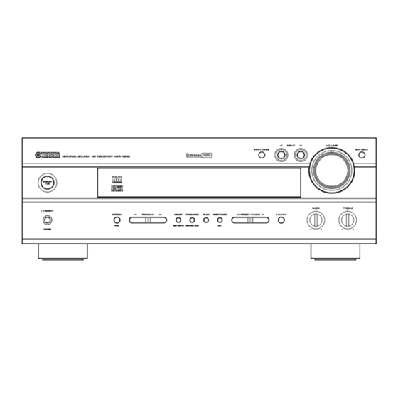
Page 3: Front Panel
HTR-5635 I FRONT PANEL I REAR PANEL I REMOTE CONTROL SYSTEM POWER POWER POWER STANDBY POWER MD/CD-R TUNER SLEEP D-TV/CBL V-AUX 6CH INPUT AUDIO DISC SKIP CODE SET VOLUME – – – MUTE INPUT MUTE HALL JAZZ ROCK ENTERTAINMENT TV SPORTS... -
Page 4: Specifications
HTR-5635 I FM Section I SPECIFICATIONS Tuning Range ................87.5 to 107.9 MHz I Audio Section 50dB Quieting Sensitivity (IHF) (1kHz, 100% Mod.) Minimum RMS Output Power (Power Amp. Section) Mono ..............2.0 µV (17.3 dBf) (20 Hz to 20 kHz, 0.06% THD, 8 ohms) Stereo .............. - Page 5 HTR-5635 • Set Menu Table MAIN MENU SUB MENU: PRESET VALUE SETTING RANGES SPEAKER SET 1A. CENTER SP: LARGE LARGE, SMALL, NONE 1B. MAIN SP: LARGE LARGE, SMALL 1C. REAR L/R SP: LARGE LARGE, SMALL, NONE 1D. LFE/BASS OUT: BOTH SW, MAIN, BOTH 1E.
-
Page 6: Internal View
HTR-5635 I INTERNAL VIEW 1 FUNCTION (9) P.C.B. 2 FUNCTION (7) P.C.B. 3 MAIN (6) P.C.B. 4 MAIN (10) P.C.B. 5 MAIN (2) P.C.B. 6 FUNCTION (3) P.C.B. 7 FUNCTION (2) P.C.B. 8 FUNCTION (10) P.C.B. 9 FUNCTION (4) P.C.B. -
Page 7: Disassembly Procedures
HTR-5635 I DISASSEMBLY PROCEDURES Top Cover (Remove parts in the order as numbered.) Disconnect the power cable from the AC outlet. 1. Removal of Top Cover a. Remove 4 screws (1) and 4 screws (2). (Fig. 1) b. Slide the Top Cover rearward to remove it. (Fig. 1) 2. - Page 8 FUNCTION (2) P.C.B. Tuner VIDEO (1) P.C.B. *1 VIDEO (2) P.C.B. *1 FUNCTION (3) P.C.B. *1: Not applied to HTR-5635 Fig. 5 6. Removal of MAIN (1), MAIN (3), MAIN (4) and MAIN (2) P.C.B. FUNCTION (5) P.C.B.s a. Remove CB253. (Fig. 6) b.
- Page 9 HTR-5635 Replacement of Power Transistor, Speaker Protective Relay It is easy to replace the power transistor and speaker protective relay of this unit according to the following procedure. a. Remove the top cover. (Refer to “1. Removal of Top Cover” on p.7.) b.
-
Page 10: Self Diagnosis Function (Diag)
3. K2 (panel key) 4. IMP SW/POWER LIMIT 5. THM/FAN OUT 6. FAN DRIVE TEST: HIGH (Not applied to HTR-5635) 7. FAN DRIVE TEST: MID (Not applied to HTR-5635) 8. FAN DRIVE TEST: LOW (Not applied to HTR-5635) 11 IF STATUS 1. - Page 11 13 SOFT SWITCH 1. SW MODE 2. MODEL SETTING 3. TUNER DESTINATION 4. TUNER EXIST 6. RDS EXIST 7. VIDEO FORMAT (Not applied to HTR-5635) 14 ROM VERSION/CHECK SUM/ 1. VERSION PORT 2. CHECK SUM ALL/PROGRAM 3. PORT 4. AAC PORT •...
- Page 12 HTR-5635 • Display provided when DIAG started When there is a history of protection Version (1 alphabet) function due to abnormal DC output The FL display of the main unit displays the protection function history data and the version (1 alphabet) and the DIAG menu (sub-menu (ANALOG BYPASS) of DIAG menu No.1 DSP THROUGH) a few seconds later.
- Page 13 HTR-5635 • Display during menu operation • Functions in DIAG mode During the DIAG operation, the function at work is In addition to the DIAG menu items, functions as listed indicated on the FL indicator. The contents displayed below are available.
- Page 14 HTR-5635 • Details of DIAG menu With full-bit output specified in some modes, it is possible to execute 0dBFS output without head margin in each channel. 1. DSP THROUGH Main DSP of YSS938 is selected for MAIN L/R output. ANALOG BYPASS •...
- Page 15 HTR-5635 YSS FULL BIT • The signal is output in digital full bit without including the head margin. Reference data INPUT: DVD ANALOG SWFR: 50Hz, Others: 1kHz SPEAKER OUTPUT (1kHz) SUBWOOFER Input level Volume MAIN L/R CENTER RL/RR OUTPUT (50Hz)
- Page 16 HTR-5635 2. RAM THROUGH This function is for YSS938 only. Only the CT signal is output through the Sub DSP - DRAM. RAM 0dB Reference data INPUT: DVD ANALOG SWFR: 50Hz, Others: 1kHz SPEAKER OUTPUT (1kHz) SUBWOOFER Input level Volume...
- Page 17 HTR-5635 3. PRO LOGIC The L/C/R/RL/RR signals undergo the Pro-Logic processing and C/RL/RR signals are output through Sub DSP-DRAM. Main DSP is selected for MAIN L/R output. Using the sub-menu, it is possible to select PRO LOGIC I, II (Movie). The Auto Input Balance function is always off.
- Page 18 DSP THROUGH: YSS 0dB. MAIN: SMALL 0dB CENTER: NONE LFE/BASS: MAIN Front Mix: 5ch REAR CENTER (Not applied to HTR-5635) The analog switch settings for each sub-menu are as shown in the table below. Sub-menu CENTER SP REAR SP MAIN SP MAIN LEVEL LFE/BASS...
- Page 19 HTR-5635 5. MARGIN CHECK The signal is output including the head margin. MAIN 12dB MARGIN Reference data INPUT: DVD ANALOG SWFR: 50Hz, Others: 1kHz SPEAKER OUTPUT (1kHz) SUBWOOFER Input level Volume MAIN L/R CENTER RL/RR OUTPUT (50Hz) - ∞ - ∞...
- Page 20 HTR-5635 6. OTHER INPUT The signal input through the 6CH INPUT terminals is output. EXTERNAL DECODER Reference data INPUT: 6CH INPUT SWFR: 50Hz, Others: 1kHz SPEAKER OUTPUT (1kHz) SUBWOOFER Input level Volume MAIN L/R CENTER RL/RR OUTPUT (50Hz) Both ch, -20 dBm -10 dB +14.3 dBm...
- Page 21 TEST REAR R TEST REAR CENTER Noise is output from the MAIN R channel. Noise is output from the REAR R channel. (Not applied to HTR-5635) TEST REAR L TEST LFE Noise is output from the REAR L Noise is output from the SUB WOOFER channel.
- Page 22 HTR-5635 • PRESET STATIONS STATION STATION PAGE FM FACTORY PRESET DATA (MHz) PAGE AM FACTORY PRESET DATA (kHz) 87.5 90.1 1080 95.1 1440 98.1 A/C/E 107.9 1710 88.1 106.1 1350 107.9 1400 10. AD DATA CHECK/FAN TEST This menu is used to display the A/D conversion value of the terminals which detects panel keys of the main unit and protection functions in % using the sub-menu.
- Page 23 THM: 500% display of the voltage based on the OPTD COAXA temperature detected value. Reference voltage : 5V (Normal value: U, C models ..30 to 173) Fan: Current fan drive level on the left and the past fan drive history on the right. (Not applied to HTR-5635)
- Page 24 HTR-5635 <2nd byte> Fs information of reproduction signal Display Fs (kHz) Analog 44.1 88.2 Unknown NRM Unknown DBL Unknown QUAD Not defined <3rd byte> A u d i o c o d e m o d e i n f o r m a t i o n o f...
- Page 25 The operation mode can be changed by selecting the sub- VIDEO FORMAT: NTSC or PAL can be selected. menu and then using the EFFECT key. With SOF selected (Not applied to HTR-5635) for the SW mode, the settings become effective. SW MODE: PCB or SOFT can be selected.
-
Page 26: Amp Adjustment
Tuner mode 0 (*1) Tuner mode 1 (*1) Tuner with (1) / without (0) RDS with (1) / without (0) VIDEO format: PAL (1) / NTSC (0) (Not applied to HTR-5635) *1 (Tuner mode) Tuner mode 1 Tuner mode 0 Tuner frequency AM: 531-1611kHz/9kHz FM: 76.0-90.0MHz/100kHz... -
Page 27: Display Data
HTR-5635 I DISPLAY DATA G V701 : HNA-16MM37 (V8300400) PATTERN AREA G PIN CONNECTION Pin No. Connection Pin No. Connection Note : 1) F1, F2 ..Filament 2) NP ..No pin 3) G1 ~ 16 ..Grid 4) NX ..No extened 5) P1 ~ 37 .. - Page 28 HTR-5635 G ANODE CONNECTION 13G~2G (MD/CD-R) (TUNER) (CD) (PHONO) (VCR) (VCR2/DVR) (VCR1) (V-AUX) (D-TV/CBL) (DVD) – – – – – –...
-
Page 29: Ic Data
HTR-5635 I IC DATA IC301: M30624FGAFP (FUNCTION P.C.B.) 16bit µ-COM (Main CPU) P07/D7 P44/CS0 P06/D6 P45/CS1 P05/D5 P46/CS2 P04/D4 P47/CS3 P03/D3 P50/WRL/WR P02/D2 P51/WRH/BHE P01/D1 P52/RD P00/D0 P53/BCLK P107/AN7 P54/HLDA P106/AN6 P55/HOLD P105/AN5 P56/ALE P104/AN4 P57/RDY/CLKOUT P103/AN3 P60/CTS0/RTS0 P102/AN2 P61/CLK0... - Page 30 HTR-5635 IC301: M30624FGAFP (FUNCTION P.C.B.) 16bit µ-COM (Main CPU) Port No. Function name Detail of function /ICCS CS493x RESET /CSOLD DIG EXTERNAL CONTROL IC CE For Flash Writing (HI) Chip Select for DAC Volume Rotary B Volume Rotary A /BLK...
- Page 31 HTR-5635 IC600 : YSS938-F RAMA9 RAMA3 SELI1 RAMA4 SELI0 SELI9 SELOA SELI10 SELOB SELI11 TESTMS SELI12 TESTXEN SELI13 IPORT0 RAMA2 IPORT1 RAMA5 IPORT2 RAMA1 IPORT3 RAMA6 IPORT4 RAMA0 DDIN0 RAMA7 DDIN1 RAMA8 DDIN2 VDD1 DDIN3 RASN RAMOEN YSS938-F AVDD RAMWEN...
- Page 32 HTR-5635 IC600 : YSS938-F Name Function Crystal oscillator connecting terminal Crystal oscillator connecting terminal (24.576MHz ) SELI1 Built-in selector input 1 (AXD) SELI0 Built-in selector input 0 (GND) SELOA Built-in selector output A (ISEL) SELOB Built-in selector output B (RSEL)
- Page 33 HTR-5635 IC600 : YSS938-F Name Function SDWCKI1 Word clock input terminal for SDIB, SDOB interface (Unconnected) SDBCKI1 Bit clock input terminal for SDIB, SDOB interface (Unconnected) Ground terminal SDOB3 PCM output terminal from Sub DSP SDOB2 PCM output terminal from Sub DSP...
- Page 34 HTR-5635 IC600 : YSS938-F Name Function RAMA5 Sub DSP: External memory address terminal 5 RAMA2 Sub DSP: External memory address terminal 2 SELI13 Built-in selector input 13 (Unconnected) SELI12 Built-in selector input 12 SELI11 Built-in selector input 11 (Unconnected) SELI10...
-
Page 35: Block Diagram
HTR-5635 I BLOCK DIAGRAM (1/2) • See page 52 → SCHEMATIC DIAGRAM • See page 51 → SCHEMATIC DIAGRAM XL600 OPERATION 24.576MHz IR REMOTE POWER RELAY U701 SPEAKER RELAY MUTE CONTROL STANDBY/ON POWER DETECT IC619A SW781 Q602 – MAIN CPU... -
Page 36: Block Diagram
HTR-5635 I BLOCK DIAGRAM (2/2) • See page 49~50 → • See page 49~50 → SCHEMATIC DIAGRAM • See page 53~54 → SCHEMATIC DIAGRAM SCHEMATIC DIAGRAM FUNCTION FUNCTION MAIN DVD/LD 8ohm/4ohm RY921 F922 SW381 D-TV/CBL INPUT SELECTOR MONITOR IC551 VCR IN... -
Page 37: Printed Circuit Board
J305 J306 Ref. No. Location X: NOT USED IC306 O: USED / APPLICABLE Q304 Q305 FUNCTION (1) P. C. B. (Lead Type Device) : Not applied to HTR-5635 FUNCTION (4) FUNCTION (4) FUNCTION (4) MD/CD-R PLAY WOOFER SURROUND INPUT MAIN... - Page 38 HTR-5635 • Semiconductor Location I PRINTED CIRCUIT BOARD (Foil side) Ref. No. Location D301 D302 D303 FUNCTION (1) P. C. B. (Surface Mount Device) D304 D305 D306 D307 D308 D309 D310 D311 D312 D313 D314 D315 IC301 IC302 IC303 IC304...
- Page 39 Ref. No. Location FUNCTION (3) P. C. B. (Lead Type Device) FUNCTION (4) P. C. B. (Lead Type Device) D571 D572 : Not applied to HTR-5635 IC551 IC571 FUNCTION (1) FUNCTION (2) P. C. B. Q301 VIDEO (1) FUNCTION (3)
- Page 40 HTR-5635 • Semiconductor Location I PRINTED CIRCUIT BOARD (Foil side) Ref. No. Location AC Power Cable D601 FUNCTION (5) P. C. B. D602 FUNCTION (7) P. C. B. D921 (Lead Type Device) MAIN (4) D922 (Lead Type Device) D923 D924...
- Page 41 HTR-5635 I PRINTED CIRCUIT BOARD (Foil side) OPERATION (1) P. C. B. (Lead Type Device) OPERATION (2) P. C. B. (Lead Type Device) FUNCTION (1) CNVSS RESET Flash µ-COM Write Connector STANDBY CTSO CLKO RXDO TXDO 6CH INPUT INPUT INPUT MODE...
- Page 42 FUNCTION (1) R653, 654, 656, 657, 659, 660, 662 R668 X: NOT USED (Lead Type Device) DSP P. C. B. O: USED / APPLICABLE : Not applied to HTR-5635 • Semiconductor Location Ref. No. Location D600 D601 D-TV/ D602 D603...
- Page 43 R653, 654, 656, 657, 659, 660, 662 R668 X: NOT USED O: USED / APPLICABLE • Semiconductor Location Ref. No. Location D604 D605 D606 D607 IC605 IC606 IC607 IC610 IC617 IC618 Q601 Q602 Q603 Q604 : Not applied to HTR-5635 : Not applied to HTR-5635...
- Page 44 HTR-5635 I PRINTED CIRCUIT BOARD (Foil side) MAIN (1) P. C. B. (Lead Type Device) MAIN (2) MAIN (3) MAIN (3) MAIN (2) MAIN (2) MAIN (10) MAIN (10) MAIN (2) MAIN (5) • Semiconductor Location Ref. No. Location Ref. No. Location Ref.
- Page 45 HTR-5635 I PRINTED CIRCUIT BOARD (Foil side) Circuit No. Circuit No. D253 D253 J381, 382 J381, 382 Q251 Q251 MAIN (2) P. C. B. (Lead Type Device) R252, 253 R252, 253 SW381 SW381 X: NOT USED X: NOT USED O: USED / APPLICABLE O: USED / APPLICABLE MAIN (3) P.
-
Page 46: Printed Circuit Board
HTR-5635 I PRINTED CIRCUIT BOARD (Foil side) MAIN (5) P. C. B. MAIN (6) P. C. B. (Lead Type Device) Circuit No. (Lead Type Device) Power Transformer C341~344, 351, 353, 354, 371~374, 376 MAIN (1) R339, 340, 351, 353, 354, 371, 372, 375... -
Page 47: Pin Connection Diagram
HTR-5635 I PIN CONNECTION DIAGRAM • ICs µPC29M33T-E1 LM61CIZ NJM78L05A-T3 NJM7805FA NJM79M05FA PQ025EZ5MZP NJM7812FA NJM79M12FA 3: IN 3: GND 3: OUT 3: IN 3: COM 2: COM 2: Vout 2: GND 1: OUT 1: OUT 1: +Vs 1: IN 1: OUT... - Page 48 HTR-5635 • Diodes 1N4002S MTZJ4.7C 1SS355 1SS133 MTZJ6.8B MA8075-H Anode 1SS176 MTZJ9.1B RB501V-40 Anode MTZJ10.0C 1SS270A UDZ5.1B MTZJ12.0C UDZ6.2B MTZJ30.0A UDZ7.5B Cathode UDZ13B Cathode UDZS5.6B UDZS6.8B S1VB20 S5VB20 – – • Transistors 2SA893A 2SC1740S 2SB1565 2SA1695 2SA1015 2SD1915F 2SD2396 2SC4468...
-
Page 49: Schematic Diagram
O: USED / APPLICABLE Point 2 emitter of Q309 Point 1 Pin 13 of IC301 and collector of Q308 MUTE A Q309 E B Q308 C POWER ON POWER OFF : Not applied to HTR-5635 (Connect the power cord) (Disconnect the power cord) - Page 50 IC551: LA7956 Video Switch 4 INPUT 1 OUTPUT DRIVER CONTROL VIDEO SWITCH VIDEO VIN1 VIN2 VIN3 VIN4 IC571: LC72722 : Not applied to HTR-5635 RDS Decoder VDDA CLOCK VDDD RECOVERY (57kHz) REFERENCE (1187.5Hz) VOLTAGE VSSA VSSD Point 3 Pin 12 of IC571...
- Page 51 HTR-5635 SCHEMATIC DIAGRAM (OPERATION) # All voltages are measured with a 10MΩ/V DC electric volt meter. # Components having special characteristics are marked s and must be replaced with parts having specifications equal to those originally installed. # Schematic diagram is subject to change without notice.
- Page 52 IC614: AK4527BVQ Function 24bit CODEC IC610: TC74HCT08AF Block 1 Quad 2-Input And Gate Macrocells 1 to 18 Audio LIN+ Not applied to HTR-5635 LIN- RIN+ Function Not applied to HTR-5635 RIN- Block 1 Macrocells 1 to 18 IC617~621: µPC4570G2 LOUT1...
- Page 53 HTR-5635 SCHEMATIC DIAGRAM (MAIN 1/2) FRONT L POWER AMP 48.0 47.9 47.3 47.7 48.0 48.0 47.3 47.2 35.9 47.7 35.9 -0.4 31.2 29.7 24.1 -1.0 31.2 30.7 32.2 RELAY DRIVER -0.5 46.7 -0.5 -1.0 -49.7 -1.0 46.1 -47.9 -46.8 47.3 46.1...
-
Page 54: Schematic Diagram
HTR-5635 SCHEMATIC DIAGRAM (MAIN 2/2) 12.1 21.0 12.0 11.7 -12.1 -21.8 -5.0 -13.1 REGULATOR x: NOT USED O: USED / APPLICABLE IC401: NJM7812FA IC403, 405: NJM7805FA Page 53 to MAIN (10) Page 53 Page 50 Voltage Regulator from FUNCTION (7) -
Page 55: Parts List
HTR-5635 PARTS LIST I ELECTRICAL PARTS I WARNING Components having special characteristics are marked s and must be replaced with parts having specifications equal to those originally installed. ABBREVIATIONS IN THIS LIST ARE AS FOLLOWS: C.A.EL.CHP : CHIP ALUMI.ELECTROLYTIC CAP L.EMIT... - Page 56 HTR-5635 P.C.B. FUNCTION Schm Schm Ref. PART NO. Description Ref. PART NO. Description V8704300 P.C.B. FUNCTION C331 UR877100 C.EL 10uF CB301 V7828200 SOCKET 15P TE TUC SERIES C332 UR877100 C.EL 10uF CB302 V7826500 CN 15P TE TUC SERIES C337 UR838100 C.EL...
- Page 57 HTR-5635 P.C.B. FUNCTION Schm Schm Ref. PART NO. Description Ref. PART NO. Description C558 UR829100 C.EL 1000uF D927 VV307700 DIODE 1N4002S C559 US063100 C.CE.M.CHP 1000pF D928 VV307700 DIODE 1N4002S C562 UR877100 C.EL 10uF s F922 VP909900 FUSE 125V C571 UR847470 C.EL...
- Page 58 HTR-5635 P.C.B. OPERATION & P.C.B. DSP Schm Schm Ref. PART NO. Description Ref. PART NO. Description V8705200 P.C.B. OPERATION Q709 VV900500 TR 2SD1991A Q,R,S CB701 VQ047200 CN.BS.PIN R741 V8070300 R.MTL.FLM 10Ω CB702 VQ047200 CN.BS.PIN R742 V8070300 R.MTL.FLM 10Ω CB703 VN394900 CN.BS.PIN SW701 VV020300 SW.TACT...
- Page 59 HTR-5635 P.C.B. DSP Schm Schm Ref. PART NO. Description Ref. PART NO. Description C646 US061330 C.CE.M.CHP 33pF C736 UA652100 C.MYLAR 100pF C647 US135100 C.CE.CHP 0.1uF C737 UA652100 C.MYLAR 100pF C648 US061330 C.CE.M.CHP 33pF C742 UR847100 C.EL 10uF C649 US135100 C.CE.CHP 0.1uF...
- Page 60 HTR-5635 P.C.B. DSP & P.C.B. MAIN Schm Schm Ref. PART NO. Description Ref. PART NO. Description G601 V8880000 TERM.GND M3.5 RJP9899 CB385 VQ585200 CN.BS.PIN G602 V8880000 TERM.GND M3.5 RJP9899 CB386 VQ584700 CN.BS.PIN G603 V8880000 TERM.GND M3.5 RJP9899 CB391 VR428800 CN.BS.PIN...
- Page 61 HTR-5635 P.C.B. MAIN Schm Schm Ref. PART NO. Description Ref. PART NO. Description C259 UR877100 C.EL 10uF D108 VN008700 DIODE 1SS270A C260 VQ462600 C.MYLAR 220pF D109 VN008700 DIODE 1SS270A C261 VQ462600 C.MYLAR 220pF D110 VN008700 DIODE 1SS270A C262 UA653100 C.MYLAR...
- Page 62 HTR-5635 P.C.B. MAIN Schm Schm Ref. PART NO. Description Ref. PART NO. Description PN331 V3750200 PIN L=70 Q260 VP883100 TR 2SC1890A D,E PN351 V3750200 PIN L=70 Q261 VP883100 TR 2SC1890A D,E PN395 V3750200 PIN L=70 Q262 V3966800 TR 2SB949 O,Y...
- Page 63 HTR-5635 P.C.B. MAIN & Chip Resistors Schm Schm Ref. PART NO. Description Ref. PART NO. Description R164 HL006100 R.MTL.OXD 1KΩ 1/2W ST101 V4040500 SCR.TERM R165 HV755100 R.CAR.FP 100Ω 1/4W ST371 V4040500 SCR.TERM s R166 V8071100 R.MTL.FLM 220Ω ST381 V4040500 SCR.TERM s R167 HV754100 R.CAR.FP...
-
Page 64: Parts List
HTR-5635 Parts List for Carbon Resistors Value 1/4W Type Part No. 1/6W Type Part No. Value 1/4W Type Part No. 1/6W Type Part No. 1.0 Ω 3100 3100 10 kΩ 7100 7100 HJ35 HF85 HF45 HF45 1.8 Ω ❊ 3180 11 kΩ... - Page 65 HTR-5635 I EXPLODED VIEW I MECHANICAL PARTS Schm Ref. PART NO. Description Remarks V8705200 P.C.B. ASS'Y OPERATION MF114180 FLEXIBLE FLAT CABLE 14P 180mm P=1.25 MF109140 FLEXIBLE FLAT CABLE 9P 140mm P=1.25 WA661300 FRONT PANEL V8315300 BUTTONCASE 1-10 V8315800 ESCUTCHEON, VOL...
-
Page 66: Remote Control
HTR-5635 I REMOTE CONTROL RAV301 G Function / Data Code List G SCHEMATIC DIAGRAM YAMAHA signal (NEC format) Label COMMON → TV POWER – (TV POWER) (TV POWER) (TV POWER) (TV POWER) (TV POWER) (TV POWER) (TV POWER) (TV POWER) →... - Page 67 HTR-5635 SYSTEM POWER POWER POWER STANDBY POWER MD/CD-R TUNER SLEEP D-TV/CBL V-AUX 6CH INPUT AUDIO DISC SKIP CODE SET VOLUME – – – MUTE INPUT MUTE HALL JAZZ ROCK ENTERTAINMENT TV SPORTS MONO MOVIE 1 - MOVIE THTR - 2...
- Page 68 HTR-5635...
Need help?
Do you have a question about the HTR-5635 and is the answer not in the manual?
Questions and answers