
Related Manuals for LiPPERT Embedded Hurricane-QM57

Summary of Contents for LiPPERT Embedded Hurricane-QM57
- Page 1 Hurricane-QM57 EPIC Express Single Board Computer Technical Manual TME-EPIC-HURQM-R2V4.docx Revision 2.4 / July 11 © LIPPERT Embedded Computers GmbH Hans-Thoma-Str. 11 D-68163 Mannheim http://www.lippertembedded.com/...
- Page 2 Contents and specifications within this technical manual are subject of change without notice. LiPPERT Embedded Computers GmbH provides no warranty with regard to this technical manual or any other information contained herein and hereby expressly disclaims any implied warranties of merchantability or fitness for any particular purpose with regard to any of the foregoing.
-
Page 3: Table Of Contents
Overview Introduction ....................1 Features ....................1 Block Diagram ..................... 2 Ordering Information ..................3 Hurricane-QM57 Models ................3 Cable Sets and Accessories ................3 Specifications ..................... 4 Electrical Specifications ................. 4 Environmental Specifications ................4 Mean Time Between Failures ................4 Mechanical .................... - Page 4 Ethernet Connector (X8, X29) ................15 USB 2.0 Ports .................... 16 USB Connectors (0-3 & 8-9, exemplary described USB 0/1, X12, X13, X14) ....16 USB Connectors (4-7, exemplary described USB 4/5, X28, X31) ....... 16 Serial ATA Ports ..................17 SATA Connector (X15, X16, X17, X19) ...............
- Page 5 BIOS ......................32 Configuring the Phoenix BIOS ................. 32 Initialize BIOS at first startup ................32 Booting from alternative device ............... 32 EFI Shell ....................33 Jumper BIOS Defaults .................. 33 BIOS Screens ..................... 34 Phoenix – SecureCore BIOS - Main Phoenix –...
- Page 6 Address Maps Memory Address Map .................. 50 I/O Address Map ..................51 Interrupts ....................53 DMA Channels .................... 53 Troubleshooting Contact Information Getting Help Additional Information Revision History TME-EPIC-HURQM-R2V4.docx Revision 2.4...
-
Page 7: Overview
1 Overview 1.1 Introduction The Hurricane-QM57 offers a high performance EPIC board with the i7-620UE, i7-610E and Celeron P4505 ® Processor Series from Intel Core™. This processor is a next generation of 64-bit, multi-core mobile processor built on 32-nanometer process technology. Based on the low-power/high-performance Nehalem micro- architecture, the Arrandale processor is designed for a two-chip platform as opposed to the traditional three-chip platforms (processor, GMCH, and ICH). -
Page 8: Block Diagram
Block Diagram TME-EPIC-HURQM-R2V4.docx Revision 2.4 Page 2 of 54... -
Page 9: Ordering Information
Custom combinations of processor and memory are possible. Minimum order quantities are required. Contact LiPPERT’s Sales Team at sales@lippertembedded.com Cable Sets and Accessories There are some options available for the Hurricane-QM57. Please check their availability before ordering. Order number Description 760-0027-10 RAM, unbuffered ECC, RSOMM, REVERSE, 2GB Operating temp. -
Page 10: Specifications
1.3 Specifications Electrical Specifications Supply voltage ATX power supply with 5V, 5V always, 3.3 volt. 12 volt DC Rise time < 10 ms Supply voltage tolerance ± 5% * Inrush current +5VSB: 1.0A +5V: 0.5A +3.3V: 0.2A +12V: 2.5A Supply current maximum** typical (idle) typical (S3) -
Page 11: Mechanical
Mechanical Dimensions (L x W) 165 mm x 115 mm Height max. 40 mm on top side above PCB max. 12 mm on bottom side above PCB Weight 275 g Mounting 4 mounting holes for PCB 4 mounting holes for PCI/104-Express/PC104+ extension cards Note It is strongly recommend using plastic spacers instead of metal spacers to mount the board. -
Page 12: Getting Started
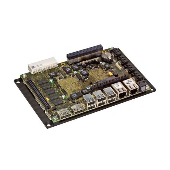
2 Getting Started 2.1 Connector Locations Backup BIOS RSOMM Connector Connector Power Connector DisplayPort Port C DisplayPort Port D 2 x USB PCI/104-Express Port 0/1 Bus Interface 2 x USB Port 2/3 PC/104-Plus Bus Interface Mini PCI Express 2 x Power USB Port 8/9 GBit Ethernet GBit Ethernet... -
Page 13: Bottom
Bottom Display Backlight Connector LVDS CPU Fan Connector Connector System Panel Chassis Fan 2 x USB 2 x USB Connector Connector Port 4/5 Connector Port 6/7 The pin 1 of the connectors is marked TME-EPIC-HURQM-R2V4.docx Revision 2.4 Page 7 of 54... -
Page 14: Jumper Locations
2.2 Jumper Locations Jumper CMOS Jumper Display Voltage Selector TME-EPIC-HURQM-R2V4.docx Revision 2.4 Page 8 of 54... -
Page 15: Led Indicators
2.3 LED indicators To facilitate problem solving, the Hurricane-QM57 provides LED indicators for the following conditions: Name Function Watchdog activated Standby Power Supply Power Mode Main Power Supply SATA accesses (Hard Disk Drive) SATA Status of wireless add-in card (WAN) -
Page 16: Hardware Setup
BIOS to load the factory settings from Flash. The Hurricane-QM57 boots from CD drives, USB floppy, USB stick, hard disk or network. Provided that any of these is connected and contains a valid operating system image, the display then shows the boot screen of your operating system. -
Page 17: Module Description
3 Module Description 3.1 Processor Intel Core i7-620UE, i7-610E and Celeron P4505 Processor Series is the next generation of 64-bit, multi-core mobile processor built on a 32- nanometer process technology. Throughout this document, Intel Core i7-620UE, ® i7-610E and Celeron P4505 Processor Series may be referred to as simply the processor. The processor is designed for a two-chip platform as opposed to the traditional three-chip platforms (processor, GMCH, and ICH). -
Page 18: Graphics-Controller
GND (RETURN) +V3.3V LVDS Configuration The Hurricane-QM57 supports 3,3V and 5V LVDS displays with 18/24bit interfaces and unconventional signal Advanced à IMC Configuration à configuration. The display type and resolution can be selected in BIOS setup: Arrandale Configuration à IGD Configuration à Panel Type. -
Page 19: Lvds Connector (X27)
The display options of LVDS are shown in the table: Setting Possible Values Flat Panel Type LVDS Resolution 640x480, 800x600, 1024x768, 1280x1024, 1400x1050, 1600x1200, 1200x768, 1600x1050, 1920x1200 Data Bus Type 18/24 Bits, 2ppc Refresh Rate 60 70, 72, 75, 85, 90, 100 Hz HSYNC Polarity High, Low VSYNC Polarity... -
Page 20: Lvds Color Mapping
LVDS Color Mapping CLKA 0/B1 CLKB 0/B1 Display Backlight Connector (X25) Connector type: Hirose DF13 8 Pin Direction Signal Output +12 V DC, max. 1A Output +12 V DC, max. 1A Output +5 V DC, max. 1A Output +5 V DC, max. 1A Output Signal: Backlight Brightness Control (level: 3.3 V) Output... -
Page 21: Gigabit Ethernet Controller
3.4 Gigabit Ethernet Controller There are two Ethernet ports available on two standard ETH connectors. One Ethernet by 82577 (Hanksville) with AMT support and the other by 82574L. Intel 82577 Gigabit Ethernet PHY The 82577 is a single port Gigabit Ethernet Physical Layer Transceiver (PHY). It connects to the Ibex Peak-M chipset’s integrated Media Access Controller (MAC) through a dedicated interconnect. -
Page 22: Usb 2.0 Ports
Ibex Peak. Thirteen USB 2.0 host ports are provided with the Hurricane-QM57. Four USB ports are available on two standard 2-port USB connectors. Another two USB ports (8/9) are available on the third standard 2-port USB connector, but they have a maximum output current of one ampere per port. -
Page 23: Serial Ata Ports
The input DMA engines move digital data from the A-D converter in the codec to system memory. The Ibex Peak implements four Serial Digital Input signals (HDA_SDI[3:0]) supporting up to four codecs. The Hurricane-QM57 uses a codec from Realtek. The ALC888 is a high-performance 7.1+2 Channel High Definition Audio Codec. -
Page 24: Audio Connector (X10)
Audio Connector (X10) Connector type: IDC16 pin header 2.00 mm Adapter cable: available, part.no. 862-0065-10 Signal Signal Line-Out R Line-Out L Surrond R Surrond L Center GND-Audio GND-Audio Line-In R Line-In L Mic R Mic L S/P-Dif IN S/P-Dif OUT PCI/104-Express Bus Interface The PCI Express architecture uses familiar software and configuration interfaces of the conventional PCI bus architecture, but provides a new high-performance physical interface while retaining software compatibility with... -
Page 25: Pci/104-Express Connector (X18)
PCI/104-Express Connector (X18) Connector Type: Samtech ASP-129637-03 Signal Signal GPIO0 PE_RST# +3.3V +3.3V USB_1+ USB_0+ USB_1- USB_0- Pex1_1Tp Pex1_0 Tp Pex1_1Tn Pex1_0 Tn Pex1_2 Tp Pex1_3 Tp Pex1_2 Tn Pex1_3 Tn Pex1_1Rp Pex1_0 Rp Pex1_1Rn Pex1_0 Rn Pex1_2 Rp Pex1_3 Rp Pex1_2 Rn Pex1_3 Rn Pex1_1Clkp... - Page 26 Signal Signal SDVO_DAT SDVO_CLK Pex16_0R(8)p Pex16_0R(0)p Pex16_0R(8)n Pex16_0R(0)n Pex16_0R(9)p Pex16_0R(1)p Pex16_0R(9)n Pex16_0R(1)n Pex16_0R(10)p Pex16_0R(2)p Pex16_0R(10)n Pex16_0R(2)n Pex16_0R(11)p Pex16_0R(3)p Pex16_0R(11)n Pex16_0R(3)n Pex16_0R(12)p Pex16_0R(4)p Pex16_0R(12)n Pex16_0R(4)n Pex16_0R(13)p Pex16_0R(5)p Pex16_0R(13)n Pex16_0R(5)n Pex16_0R(14)p Pex16_0R(6)p Pex16_0R(14)n Pex16_0R(6)n Pex16_0R(15)p Pex16_0R(7)p Pex16_0R(15)n Pex16_0R(7)n Note: The voltages +5V, +5VAlways and +12V are not generated by the onboard power-supply but routed from the Power Supply Connector.
-
Page 27: Pc/104-Plus Bus Interface
PC/104-Plus Bus Interface The PC/104-Plus bus is a modification of the standard PCI bus. It allows all of the PC/104 features to be used, together with the high speed PCI bus. The main features are: · PC/104-Plus Bus slot, fully compatible with PCI version 2.2 specifications. ·... -
Page 28: Pc/104-Plus Connector (X32)
PC/104-Plus Connector (X32) Connector Type: BSV-PC104-PLUS-EPT Reserved +5 Volts AD00 VI/O AD02 AD01 +5 Volts AD05 AD04 AD03 C/BE0 AD07 AD06 AD09 AD08 AD11 VI/O AD10 M66EN AD14 AD13 AD12 n.c. C/BE1 AD15 n.c. SERR PERR n.c. SDONE STOP n.c. LOCK n.c. -
Page 29: Pcie Mini-Card (X9)
3.10 PCIe Mini-Card (X9) The PCIe Mini Card (or Mini PCI Express) interface can be used to add IO functionality to the board. Different Mini PCI Express boards on the market are available with functionality like WLAN or SSD (Solid State Disk) Connector type: Molex 67910-9001 Signal... -
Page 30: On Board Power Supply
3.11 On Board Power Supply The ATX power supply generates all necessary voltages. The 3.3V (also 5V, 12V, (-12V)) available on the PC104 Plus and PCI/104-Express Connectors is delivered directly from the external power supply unit, so refer to the specification of your power supply unit for information on maximum available power on the PCI104 Plus and PCI/104-Express connectors. -
Page 31: System Panel Connector (X5)
3.12 System Panel Connector (X5) That connector is used by a different kind of signals. There is no standard cable adapter available. Connector type: DF14 20pin header 1.25 mm SMBus/I²C The ICH9 contains an SMBus (System Management Bus) Host interface that allows the processor to communicate with SMBus slaves. -
Page 32: Reset-Button
Reset-Button To reset the board, the signal “Reset-Button” must be pulled to GND. Signal Signal SMB_CLK SMB_DATA Power Button Reset Button HDD LED +3.3V Watchdog +3.3V Power LED +3.3V GPIO GPIO GPIO GPIO GPIO GPIO GPIO GPIO HDD-LED To see the HDD activation, the signal "HDD LED" must be pulled to +3.3V. Signal Signal SMB_CLK... -
Page 33: Power-Led
Power-LED To see the Power activation, the signal "Power LED" must be pulled to +3.3V. Signal Signal SMB_CLK SMB_DATA Power Button Reset Button HDD LED +3.3V Watchdog +3.3V Power LED +3.3V GPIO GPIO GPIO GPIO GPIO GPIO GPIO GPIO GPIO’s Signal Signal SMB_CLK... -
Page 34: Lpc Bus
3.14 LPC Bus The PCH implements an LPC (Low Pin Count) interface, which is supported via this connector. LPC Connector (X4) Connector Type: DF13 12 pin header 1.25 mm Signal +3V3 LPC_AD0 LPC_AD1 LPC_AD2 LPC_AD3 n.c. LPC_FRAME# PCI_RST# CLK_33_FWH INT_SERIRQ LPC_DRQ# Caution The maximum current on the supply pin is 0.3A! -
Page 35: Board Specific Lemt Functions
This counter gives the User information of Temperature/Cooling problems. This counter is cleared when the system is removed from power. The Hurricane-QM57 monitors the CPU- and Board-temperature and does not support TS#-Events. - Page 36 The SMC Flags return the last detected Exception Code since Power-up. The upper 3 bits of the SMC Flags register are reserved for future use. SMC Status This register show of the status of SMC controlled signals on the Hurricane-QM57. Status Bit Signal SMC_WDACTIVE# TME-EPIC-HURQM-R2V4.docx...
-
Page 37: Cpu Fan Connector (X20)
3.16 CPU Fan Connector (X20) The Hurricane-QM57 provides a connector to power a CPU fan, if the module is actively cooled. Connector Type: HIROSE-DF13-3PIN-1M25-S Signal Speed Signal from fan (yellow) +12VDC, regulated (red) GND (black) 3.17 Chassis Fan Supply (X21) The Hurricane-QM57 provides a connector to power a Chassis fan. -
Page 38: Using The Module
4 Using the Module 4.1 BIOS The Hurricane-QM57 is delivered with a Phoenix Technology BIOS. The default settings guarantee a "ready to run" system, even without a BIOS setup backup battery. All setup changes of the BIOS are stored in the CMOS RAM. A copy of the CMOS RAM, excluding date and time, is stored in the flash memory. -
Page 39: Efi Shell
EFI Shell To start the EFI Shell you have to pressing the <F11> key at power-up. Jumper BIOS Defaults To reload the default values automatically at power up the jumper “BIOS Defaults” must be plugged before power up. On power up the BIOS will recognize plugged jumper and load the setup defaults. TME-EPIC-HURQM-R2V4.docx Revision 2.4 Page 33 of 54... -
Page 40: Bios Screens
BIOS Screens The BIOS setup utility allows setting of various board parameters. The following pictures show the different setup menus. The Hurricane-QM57 specific settings are explained here. Phoenix – SecureCore BIOS - Main Phoenix – SecureCore BIOS – Main – System Information TME-EPIC-HURQM-R2V4.docx... -
Page 41: Advanced
Advanced Advanced – Boot Configuration TME-EPIC-HURQM-R2V4.docx Revision 2.4 Page 35 of 54... -
Page 42: Advanced – Acpi Configuration
Advanced – ACPI Configuration Advanced – Processor Configuration TME-EPIC-HURQM-R2V4.docx Revision 2.4 Page 36 of 54... -
Page 43: Advanced – Processor Configuration – Processor Power Management
Advanced – Processor Configuration – Processor Power Management Advanced – Peripheral Configuration TME-EPIC-HURQM-R2V4.docx Revision 2.4 Page 37 of 54... -
Page 44: Advanced – Hdd Configuration
Advanced – HDD Configuration Advanced – IMC Configuration TME-EPIC-HURQM-R2V4.docx Revision 2.4 Page 38 of 54... -
Page 45: Advanced – Imc Configuration – Nb Common Configuration
Advanced – IMC Configuration – NB Common Configuration Advanced – IMC Configuration – NB Common Configuration – VT for Directed I/O TME-EPIC-HURQM-R2V4.docx Revision 2.4 Page 39 of 54... -
Page 46: Advanced – Imc Configuration – Nb Common Configuration – Video Configuration
Advanced – IMC Configuration – NB Common Configuration – Video Configuration Advanced – IMC Configuration – Arrandale Config TME-EPIC-HURQM-R2V4.docx Revision 2.4 Page 40 of 54... -
Page 47: Advanced – Imc Configuration – Arrandale Config – Peg Configuration
Advanced – IMC Configuration – Arrandale Config – PEG Configuration Advanced – IMC Configuration – Arrandale Config – IGD Config TME-EPIC-HURQM-R2V4.docx Revision 2.4 Page 41 of 54... -
Page 48: Advanced – Imc Configuration – Arrandale Config – Igd Config – Boot Type
Advanced – IMC Configuration – Arrandale Config – IGD Config – Boot Type Advanced – IMC Configuration – Arrandale Config – IGD Config – Panel Type TME-EPIC-HURQM-R2V4.docx Revision 2.4 Page 42 of 54... -
Page 49: Advanced – South Bridge Config
Advanced – South Bridge Config Advanced – South Bridge Config – SB PCI Express Config TME-EPIC-HURQM-R2V4.docx Revision 2.4 Page 43 of 54... -
Page 50: Advanced – South Bridge Config – Sb Pci Express Config – Pci Express Root Port1
Advanced – South Bridge Config – SB PCI Express Config – PCI Express Root Port1 Advanced – Network Configuration TME-EPIC-HURQM-R2V4.docx Revision 2.4 Page 44 of 54... -
Page 51: Advanced – Smbios Event Log
Advanced – SMBIOS Event Log Advanced – ME Configuration TME-EPIC-HURQM-R2V4.docx Revision 2.4 Page 45 of 54... -
Page 52: Advanced – Thermal Configuration
Advanced – Thermal Configuration Advanced – Thermal Configuration – Processor Thermal Management Submenu TME-EPIC-HURQM-R2V4.docx Revision 2.4 Page 46 of 54... -
Page 53: Advanced – Thermal Configuration – Intelligent Power Sharing
Advanced – Thermal Configuration – Intelligent Power Sharing Advanced – Thermal Configuration – Platform Thermal Configuration TME-EPIC-HURQM-R2V4.docx Revision 2.4 Page 47 of 54... -
Page 54: Security
Security Boot TME-EPIC-HURQM-R2V4.docx Revision 2.4 Page 48 of 54... -
Page 55: Exit
Exit 4.2 Drivers Software drivers for Chipset, Ethernet and graphics adapter are available for the Hurricane-QM57. These drivers can be downloaded from LiPPERT's website http://www.lippertembedded.com. Follow the installation instructions that come with the drivers. TME-EPIC-HURQM-R2V4.docx Revision 2.4 Page 49 of 54... -
Page 56: Address Maps
5 Address Maps This section describes the mapping of the CPU memory and I/O address spaces. Note: Depending on enabled or disabled functions in the BIOS, other or more resources may be used Memory Address Map Address Range (Hex) Description 000A0000-000BFFFF PCI-Bus 000A0000-000BFFFF... -
Page 57: I/O Address Map
Address Range (Hex) Description FED45000-FED8FFFF Resources FEE00000-FEEFFFFF Resources FF000000-FFFFFFFF Resources FF000000-FFFFFFFF Firmware Hub I/O Address Map The system chipset implements a number of registers in I/O address space. These registers occupy the following map in the I/O space (depending on enabled or disabled functions in the BIOS other or more resources may be used). - Page 58 Address Range (Hex) Description 00A8-00A9 Interrupt Controller 00AC-00AD Interrupt Controller 00B0-00B1 Interrupt Controller 00B2-00B3 Resources 00B4-00B5 Interrupt Controller 00B8-00B9 Interrupt Controller 00BC-00BD Interrupt Controller 00C0-00DF DMA Controller 00F0-00F0 Math Coprocessor 01CE-01CF VGASave 0274-0277 ISAPnP Data port 0279-0279 ISAPnP Data port 02E8-02EF VGASave 03B0-03BB...
-
Page 59: Dma Channels
Address Range (Hex) Description 18B0-18B7 SATA Controller – 3B2D 18B8-18BF SATA Controller – 3B2D 2000-201F Ethernet Controller 82574L 2000-2FFF PCI Express – 3B4A FE00-FE00 Resources FFFF-FFFF Resources Interrupts IRQ (Bus) System Resource 0 (ISA) Timer 8 (ISA) Timer 9 (ISA) ACPI-conform System 13 (ISA) Math coprocessor... -
Page 60: Troubleshooting
6 Troubleshooting First steps if the board does not boot: · Check the status LEDs on the board. Are all voltages properly available? · Check the power connectors to the board, monitor and additional devices. · Are all cables plugged on the correct connector and in the correct orientation? The board may not boot if some of the cables are not plugged in correctly! ·... -
Page 61: Contact Information
Contact Information Headquarters LiPPERT Embedded Computers GmbH Hans-Thoma-Straße 11 68163 Mannheim Germany Phone +49 621 432140 +49 621 4321430 E-mail sales@lippertembedded.com support@lippertembedded.com Website www.lippertembedded.com US Office LiPPERT Embedded Computers, Inc. 2220 Northmont Parkway, Suite 250 Duluth, GA 30096 Phone +1 (770) 295 0031... -
Page 62: Getting Help
Getting Help Should you have technical questions that are not covered by the respective manuals, please contact our support department at support@lippertembedded.com. Please allow one working day for an answer! Products Technical manuals as well as other literature for all LiPPERT products can be found in the section of LiPPERT's website www.lippertembedded.com. -
Page 63: Additional Information
Additional Information Universal Serial Bus (USB) connects computers, peripherals and more at www.usb.org PCI-Express PCI Express Specification, Revision 1.1 at www.pcisig.com/specifications/pciexpress/ ACPI Advanced Configuration and Power Interface Specification (ACPI), Revision 3.0 at www.acpi.info/spec.htm System Management Bus (SMBus) at www.smbus.org TME-EPIC-HURQM-R2V4.docx Revision 2.4 Appendix C... -
Page 64: Revision History
Revision History Filename Date Edited Change TME-EPIC-HURQM-R0V0.doc 2009-11-09 Draft TME-EPIC-HURQM-R0V1.doc 2010-04-23 Some Layout changes Included Celeron P4505 TME-EPIC-HURQM-R0V2.doc 2010-04-27 Changes at chapter 5 TME-EPIC-HURQM-R0V3.doc 2010-05-17 Changes at chapter 4 TME-EPIC-HURQM-R0V4.doc 2010-06-24 Changes at chapter 3.5 TME-EPIC-HURQM-R0V5.doc 2010-07-15 Changed Block Diagram TME-EPIC-HURQM-R0V6.doc 2010-09-09 Ch.
Need help?
Do you have a question about the Hurricane-QM57 and is the answer not in the manual?
Questions and answers