Table of Contents
Advertisement
Quick Links
Advertisement
Table of Contents

Related Manuals for Brivis Iceberg


Summary of Contents for Brivis Iceberg
- Page 1 Service shall be carried out only by Authorised Personnel. This Service Manual must NOT be left with the Owner, or distributed to other persons not permitted to obtain this information by Brivis Climate Systems. 285 Issue 1 - Service Manual - Iceberg...
- Page 2 Issue Date Description March Release of the Iceberg cooler Model number: 2015 XQ4 ICEBERG 285 Issue 1 - Service Manual - Iceberg...
-
Page 3: Table Of Contents
7.4 Water Inlet Solenoid – If power present and doesn’t open: ..........16 7.5 Water Inlet Solenoid – If NO power: ..................16 7.6 Water Inlet Solenoid – Does not turn OFF ................17 8.0 Brivis Aquastop ........................17 9.0 Circulation Pump ........................18 285 Issue 1 - Service Manual - Iceberg... - Page 4 13.2 Potentiometer - Drain refill cycle count ................38 14.0 Evaporator Module – Primary Drain ................... 39 14.1 Safety Tray – Secondary Drain ..................39 15.0 Final Checklist ........................40 16.0 Iceberg Cooler Service ....................... 41 285 Issue 1 - Service Manual - Iceberg...
- Page 5 The Brivis Iceberg™ evaporative cooler is a new design where the evaporation process takes place beneath the roof line. The Brivis Icecap™™™ is an optional accessory located on the roof of the home and is designed to provide the minimum ventilation requirement of 0.5m² to the Evaporator Module installed within the roof space.
-
Page 6: Operation Overview
450mm diameter. Fresh air is drawn into the unit via the air inlet mesh when the damper assembly (winterseal) has opened enabling air flow into the home. The Iceberg Evaporator Module has 4 Hydrochill pads fitted. There are 2 pads on either side of the module. -
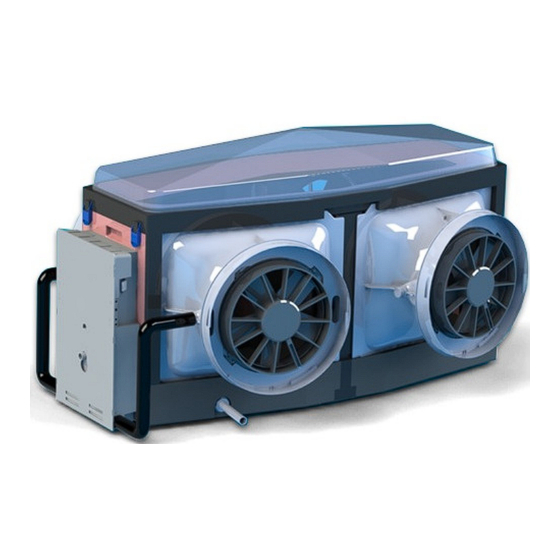
Page 7: Component Overview
Control Service panel Isolation Primary Drain Discharge Water switch Fan assembly Discharge Inlet 2.2 Evaporator Module - Internal Circulation Pump Drain Pump Pump Water Water Outlet distribution outlet distribution pipe Drain pipe 285 Issue 1 - Service Manual - Iceberg... -
Page 8: Service Control Panel
2 x Fan Power Water Solenoid Supplies Valve 2.4 Brivis Icecap™ - Components Mesh Screen Brivis Icecap™ (Plastic) BAL Icecap™ (Metal) Note: For installation requirements refer to the Appendix for more detail. 285 Issue 1 - Service Manual - Iceberg... -
Page 9: Component Overview
The optional Icecap™™™ is an accessory that is installed on the roof to assist with the Iceberg’s ventilation requirements. Further information on installation and operation of Brivis Iceberg Evaporative Coolers can be obtained from the Cooling Installer’s Manual and Cooling Owner’s manual... -
Page 10: Technical Data Sheet Xq4
1-0-0-0 Wall Controller Water Connection Tek700 Iceberg Wall Control Flexible Hose Connection with 3/4" BSPF (female) Drain Connection Evaporator unit size 20mm DN pressure pipe Safety Tray outlet size 40 mm DWV 285 Issue 1 - Service Manual - Iceberg... -
Page 11: Wiring Diagram
3.1 Wiring Diagram 285 Issue 1 - Service Manual - Iceberg... -
Page 12: Main Control Board Connections
Motor power Speed Control pump supply to Fan Signal Modules (0-10Volts) Fan Motor Supply Module Fan Motor Earth Fan Motor (B) Neutral Neutral (A) Neutral Fan Motor Fan Motor (B) Neutral (A) Neutral 285 Issue 1 - Service Manual - Iceberg... -
Page 13: Cooler Operation
The following will occur: • When the wall control is turned OFF the Iceberg Cooler will drain the water after a 45min delay time. The pump will then turn on and continuously run for 10min. During this 10 min on-time the solenoid will open for 30sec to back wash any sediments left in the unit •... -
Page 14: Cooler Operation - Manual Sequence
Damper (winterseal) The drain pump will open operates for 7 min 30 sec then stops. Fan turns on and Unit stops (10 min operates at its set cycle) speed. (4 min Cycle) 285 Issue 1 - Service Manual - Iceberg... -
Page 15: Cooler Operation - Auto Sequence
If the room temperature is higher than the set point when the Networker is turned ON, then the fan will immediately operate at the speed according to the set point, following the normal ServoSeal, water fill and Pre-wet operations. 285 Issue 1 - Service Manual - Iceberg... -
Page 16: Installation Requirements
5.0 Installation Requirements The below section provides an overview of the platform installation requirements; for more detail refer to the Iceberg™ Installation manual. 5.1 XQ4 Dimensions 5.2 Platform & Service Clearance – With Module 285 Issue 1 - Service Manual - Iceberg... -
Page 17: Platform & Service Clearances - Without Module
The electricity supply must be 240 Volt / 50 Hertz, and from an authorised power supplier. Generators should never be used, as their output may be incompatible with or damage the Cooler’s electronic control system. 285 Issue 1 - Service Manual - Iceberg... -
Page 18: Water Supply To The Evaporator Module
Diagram Note: The 3/4” BSPM thread on unit is plastic, be careful not to cross thread. Aquastop at the Water tap end of the braided line is ¾” BSPF. 285 Issue 1 - Service Manual - Iceberg... -
Page 19: Solenoid Valve
7.0 Solenoid Valve 7.1 Water Inlet Solenoid Operation The Iceberg Cooler has a 240 Volt water inlet solenoid which is located at the front of the service compartment. The water inlet solenoid has a filter within and attached is a flexible hose or braided line, which is terminated with a ½”... -
Page 20: Water Inlet Solenoid - Does Not Supply Water Into The Tank When Empty
• Checks that (both the High and Low Level Sensors are open Circuit) are not current. • Check that the water inlet solenoid is energised (240 Volt), at the water INLET SOLENOID- ACTIVE and INLET SOLENOID – NEUTRAL terminals. Neutral Active Check if 240 Volts Present 285 Issue 1 - Service Manual - Iceberg... -
Page 21: Water Inlet Solenoid - If Power Present And Doesn't Open
• Replace control board and check for output voltage to the water inlet solenoid If water inlet solenoid doesn’t operate: • Check wiring terminals and loom • Check water inlet solenoid is not blocked or jammed • Replace water inlet solenoid. 285 Issue 1 - Service Manual - Iceberg... -
Page 22: Water Inlet Solenoid - Does Not Turn Off
“Aquastop” from the bi-directional valve adjacent to the unit. Once the pressure has relieved fasten the “Aquastop” back onto the bi-directional valve and turn on the mains supply tap. 285 Issue 1 - Service Manual - Iceberg... -
Page 23: Circulation Pump
9.0 Circulation Pump The Iceberg Cooler has 2 different working pumps, one of which is a drain pump and the other is the main circulation pump. Both pump motors have a thermal overload function and are powered by 240 Volt from the main control board. The main Circulation pump also has a distinct filter base tray and can be easily identified when looking at both pumps. -
Page 24: Pump Removal
Remove the pump wiring loom away from the main control board. Pull the pump away from the distribution pipe. Lift upwards and away from the base of the unit. 285 Issue 1 - Service Manual - Iceberg... -
Page 25: Circulation Pump - Electrical Checks
Trident probes Check for 240 Volt output to the pump, at the PUMP-NEUTRAL and PUMP-ACTIVE • terminals on the pump. Neutral Active Testing across the two terminals should read 240 Volts 285 Issue 1 - Service Manual - Iceberg... -
Page 26: If Power Present
• Check the pump loom and all terminals. • Check the Main control board 630 mA fuse is not open circuit. • Replace Main Control and re-test. • Replace Wall Control and re-test. 285 Issue 1 - Service Manual - Iceberg... -
Page 27: If Pump Doesn't Operate
Replace the Circulation pump assembly, if impellor is damaged or jammed. • 9.3 Drain Pump This pump is the same pump type as the circulation pump. To diagnose this pump please refer to the procedure detailed above. 285 Issue 1 - Service Manual - Iceberg... -
Page 28: Winter Seal Damper Assembly
10.0 Winter seal damper assembly The new Brivis Iceberg Cooler has a new and unique mechanism, which is adjustable louver constructed in the top of the Acoustic Cooling Chamber. The can be driven closed and prevents heat loss from the building when the unit is not in use. -
Page 29: Dismantling
Remove the Toggle clips and lift the chambers lid up and away from the unit. Turn the lid upside down to expose the grub screw and unscrew using an allen key. 285 Issue 1 - Service Manual - Iceberg... - Page 30 Once you have pulled the bracket away from the blade, pull the blade away from the damper motor assembly end. 285 Issue 1 - Service Manual - Iceberg...
-
Page 31: Damper Motor Assembly Will Not Open
• Replace the complete damper motor assembly. • Neutral Active Check if 240 Volt power is present on the damper motor assembly switch A and Motor B active open terminal and Neutral 285 Issue 1 - Service Manual - Iceberg... -
Page 32: If Power Is Present At The Motor Terminal
10.4.1 If damper motor assembly does not operate: Replace damper motor assembly • 10.4.2 If motor operates: Check linkages are free moving and not jammed. • Check gear linkage mechanism is not jammed. • Replace gear linkage mechanism. • 285 Issue 1 - Service Manual - Iceberg... -
Page 33: If No Power Present At Servoseal Motor Active Open Terminal
10.4.4 If winter seal damper motor operates: Check wiring and connections for open circuit. • Replace main control board and re test. • 10.4.5 If winter seal damper motor doesn't operate: • Replace damper motor assembly. 285 Issue 1 - Service Manual - Iceberg... -
Page 34: Damper Blade Will Not Close
2 minute – after the fans are turned off. Follow check procedures as above for damper blade will not open, with • power test to Active Close terminal on the damper motor assembly and switch. 10.4.7 Circuit Diagram: 285 Issue 1 - Service Manual - Iceberg... -
Page 35: Fan Motor Assembly
11.0 Fan Motor Assembly The Iceberg XQ4 has 4 fan motor assemblies. (Model AR300D3-DF0-07) which run on 48DC Volts. The assemblies are located on both sides of the Cooler and are also connected to the ducting outlet connections. There are 2 Fan Power Modules to control the 2 fan motors. Refer to... -
Page 36: Fan Motor Assembly Removal
Then remove it away from the cooler chamber. You then need to remove the 2 screws and nuts that hold the fan motor onto the ductwork connection pop. 285 Issue 1 - Service Manual - Iceberg... -
Page 37: Fan Motor Will Not Operate
Check the motor winding resistance (refer Motor Circuit Diagram and Technical • Information Sheet). Red (Active) Blue (Neutral). The motor resistance should be approx 2.86MOhms. Red (Active) Yellow (Speed Control) 0.27 Ohms 285 Issue 1 - Service Manual - Iceberg... - Page 38 (Active) and Blue (Neutral) on both Fan Power Module (GF600-1C-AM) located in the service compartment. NOTE: PLEASE ENSURE YOU CHECK THIS ON DC VOLTS If 48 Volt DC is present: • Replace Motor 285 Issue 1 - Service Manual - Iceberg...
-
Page 39: Brivis Iceberg Wall Control
Ensure there is a good connection on the board and the back of the wall control. Operating your wall control The Iceberg Programmable Wall Controller gives the choice of Automatic or Manual modes with the option of a time ON or OFF delay. Automatic Pre-Wet When the cooler is turned on with the fan and the pump, in either Auto or Manual mode, the cooler will start a Pre-Wet stage to ensure the pads are thoroughly wet before the fan starts. - Page 40 The longer the column, the cooler the settings; the shorted the column , the warmer the setting. Benefits of using the Brivis Iceberg in “AUTOCOOL” mode in preference to “MANUAL” mode. • Power and water consumption varies in relation to the chosen comfort level.
- Page 41 OFF time. 4 Press the TIMER button to save the timer setting. 5 Controller will return to previous On mode setting and time until OFF will be displayed, eg. OFF IN 4:00. 285 Issue 1 - Service Manual - Iceberg...
-
Page 42: Dip Switches & Potentiometer
13.0 Dip Switches & Potentiometer 13.1 Dip Switch Settings Dip Switch on the main control board are parameters that distinguish what the Iceberg configuration is. Detailed descriptions of the parameters are on the chart below. Positions Descriptions 1-0-0-0 1 Wall controller for 4 zones (CPI= All Fans) -
Page 43: Potentiometer - Drain Refill Cycle Count
Service technicians can adjust the occurrence of the flush operation if necessary. The iceberg will leave the factory at 150 refills (position 9) as its features the aquasave to purify the water this reducing the drain cycle. -
Page 44: Evaporator Module - Primary Drain
14.0 Evaporator Module – Primary Drain Brivis recommend the drain outlet be plumbed to a suitable point in order to disperse the waste water away adequately without causing damage or nuisance i.e. no overflowing. Ensure that all field supplied drainage pipe is rigid (not flexible) and UV stabilised if exposed to the external environment. -
Page 45: Final Checklist
3. Change dip switch setting from “1,0,0,0” (Run configuration) to “0,1,0,1” (Installation Check configuration) 4. Place control panel cover back onto the unit 5. Turn power back onto the Brivis Iceberg™ and the “Installation Check” will start automatically and proceed through the following sequence a. WinterSeal will open. -
Page 46: Iceberg Cooler Service
16.0 Iceberg Cooler Service Pre Season Maintenance The service to a Iceberg requires access to the home to check the performance of the unit through the duct system and the function of the wall control. Service work performed without access cannot be responsible for the system operation, only the Coolers function. - Page 47 Check the air distribution is correctly balanced. Check there is adequate exhaust opening available for correct operation. Check the Iceberg wall control is located in a suitable position for correct operation. Check the unit operates in both Manual and Auto modes.
- Page 48 © Brivis Climate Systems Pty. Ltd. 2015. All rights reserved. No part of these documents may be used in any way or form without prior written consent from Brivis Climate Systems Pty Ltd. March 2015 285 Issue 1 - Service Manual - Iceberg...
Need help?
Do you have a question about the Iceberg and is the answer not in the manual?
Questions and answers