
Summary of Contents for Omicron CP SB1
-
Page 1: User Manual
CP SB1 TRANSFORMER SWITCH BOX FOR MEASURING RATIO AND WINDING RESISTANCE AND TESTING THE TAP CHANGER OF POWER TRANSFORMERS User Manual... - Page 2 All rights including translation reserved. Reproduction of any kind, for example, photocopying, microfilming, optical character recognition and/or storage in electronic data processing systems, requires the explicit consent of OMICRON electronics. Reprinting, wholly or in part, is not permitted. The product information, specifications, and technical data embodied in this manual represent the technical status at the time of writing and are subject to change without prior notice.
-
Page 3: Table Of Contents
Circuit Diagram of the CP SB1 ........14 Functional Components of the CP SB1 ....... 15 CP SB1 Accessories . - Page 4 CP SB1 User Manual Technical Data ..........53 Specifications.
-
Page 5: Using This Manual
The CP SB1 User Manual always has to be available at the site where the CP SB1 is used. It must be read and observed by all users of the CP SB1. Reading the CP SB1 User Manual alone does not release you from the duty of complying with all national and international safety regulations relevant to working with the CPC 100 and CP SB1. -
Page 6: Conventions And Symbols Used
Equipment damage or loss of data possible. Personal injury or severe damage to objects possible. Related Documents The following documents complete the information covered in the CP SB1 User Manual: Title Description CPC 100 User Manual Contains information on how to use the CPC 100 test system and relevant safety instructions. -
Page 7: Safety Rules
Depending on the application and the device under test, specific safety instructions must be observed. Very often, the danger coming from the device under test is even higher than the danger from the CP SB1 itself. For application-specific safety instructions, see 3.1 "Safety Instructions for Connecting the CP SB1 to Power Transformers"... - Page 8 Make sure that the test object's terminals that are to be connected to the CP SB1 or CPC 100 do not carry any voltage potential. During a test, the only power source for a test object may be the CPC 100.
-
Page 9: Dc Output To Test Objects With A High Inductance
Do not operate the CP SB1 in the presence of explosives, gas or vapors. • Opening the CP SB1 invalidates all warranty claims. • If the CP SB1 or any add-on device or accessory does not seem to function properly, do not use it anymore. Please call the OMICRON electronics hotline. •... -
Page 10: Static Charges
Orderly Measures The CP SB1 User Manual or alternatively the e-book in PDF format has always to be available on site where the CP SB1 is being used. It must be read and observed by all users of the CP SB1. -
Page 11: Disclaimer
Safety Rules Following the instructions provided in this User Manual is also considered part of being in accordance with the regulations. Disclaimer If the equipment is used in a manner not specified by the manufacturer, the protection provided by the equipment may be impaired. - Page 12 CP SB1 User Manual...
-
Page 13: Hardware Information
Therefore, no rewiring is required. The CP SB1 is controlled from the CPC 100 via its serial interface. The results are recorded in the CPC 100 with the ratio and tap changer test cards, and can be... -
Page 14: Circuit Diagram Of The Cp Sb1
CP SB1 User Manual Circuit Diagram of the CP SB1 To Transformer To Transformer To Tap Changer High High Voltage Voltage Voltage Voltage Measure (M) Source (S) Down Overcurrent protection Measurement Power Relays Relays Matrix Matrix Surge arrestor Control unit... -
Page 15: Functional Components Of The Cp Sb1
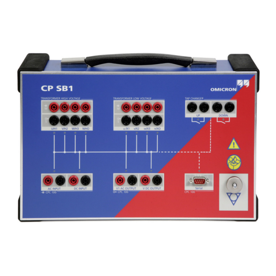
Hardware Information Functional Components of the CP SB1 The front panel of the CP SB1 provides the following functional components: • Transformer High Voltage: – Outputs (Source) for the input of current or voltage on the individual phases of the transformer –... - Page 16 CP SB1 User Manual Tap Changer Transformer High Transformer Low Read the Voltage Voltage Down manual LEDs V1 AC Output V DC Output Serial Equipotential DC Input AC Input connection ground terminal Figure 1-2 Front panel...
-
Page 17: Cp Sb1 Accessories
Hardware Information CP SB1 Accessories The following accesories are delivered with the CP SB1 tranformer switch box: Table 1-1 CP SB1 Accessories Accessories Description 1x Transport case To transport the entire equipment Coax. cables Connection from the CP SB1 to the 15 m/2.5 mm... - Page 18 Accessories Description 8 Kelvin clamps Connection to bushings black 6x Flexible terminal Connection to tap adapter changer 1x Data cable Connection from the CP SB1 to the CPC 100 grey 1x Backpack To transport the cable drums and Kelvin clamps...
-
Page 19: Operation
Operation Operation Measurement Setup The measurement setup consists of the CPC 100 test system and the CP SB1 transformer switch box. Figure 2-1 "Measurement setup" shows the functional setup. Figure 2-1 Measurement setup... -
Page 20: Operating Principle
An integrated logic which is controlled by the CPC 100 controls the relays and the OLTC. The CP SB1 has two outputs to operate the tap changer together with an optimized "Auto Keep Result" algorithm within the TRTapCheck test card. -
Page 21: Application
3.1.2 Connecting the Measurement Setup to Power Transformers 1. Position the CP SB1 in the safety area and do not enter this area during the entire measurement. 2. Connect the CPC 100 and CP SB1 using the delivered grounding cable. - Page 22 "up" and "down" terminals of the tap changer. 11.Connect the cables ("up", "down") to the CP SB1. 12.Connect the CP SB1 to the CPC 100 according to 1.3 "Functional Components of the CP SB1" on page 15. 13.Switch on the power supply of the tap changer.
-
Page 23: Template Usage
CPC 100 Start Page appears on your desktop, where you can start the Excel CPC 100 File Loader. Templates are pairs of XML documents and Microsoft Excel templates designed by OMICRON electronics or end users for designated applications. The XML templates are predefined test procedures, often with comments, that run on the CPC 100 and guide the user through the test. -
Page 24: Trratio Test Card
CP SB1 User Manual For power transformers, the following test cards are available: Figure 3-1 Inserting test cards Highlight the test card of your choice either by navigating with the handwheel or by using the context-dependent Up/Down menu keys, and then press Enter. - Page 25 Application Table 3-1 Different Vector Groups Winding connection Mea- Trans- Trans- Mea- 60076 sure- former former sured vec- ment high- low-voltage turn voltage side side ratio group HV / H LV /X U-V / H1-H2 u-v / X1-X2 V/H2 v/X2 U/H1 W/H3 u/X1...
- Page 26 CP SB1 User Manual Table 3-1 Different Vector Groups (continued) Winding connection Mea- Trans- Trans- Mea- 60076 sure- former former sured vec- ment high- low-voltage turn voltage side side ratio group HV / H LV /X U-V / H1-H2 v-w / X2-X3...
- Page 27 Application Table 3-1 Different Vector Groups (continued) Winding connection Mea- Trans- Trans- Mea- 60076 sure- former former sured vec- ment high- low-voltage turn voltage side side ratio group HV / H LV /X Dyn5 U-V / H1-H2 n-u / X0-X1 1*√3 u/X1 V/H2...
- Page 28 CP SB1 User Manual Table 3-1 Different Vector Groups (continued) Winding connection Mea- Trans- Trans- Mea- 60076 sure- former former sured vec- ment high- low-voltage turn voltage side side ratio group HV / H LV /X Dyn11 U-V / H1-H2 u-n / X1-X0 √3...
- Page 29 Application Table 3-1 Different Vector Groups (continued) Winding connection Mea- Trans- Trans- Mea- 60076 sure- former former sured vec- ment high- low-voltage turn voltage side side ratio group HV / H LV /X Dzn2 U-(V+W) / n-v / X0-X2 v/X2 u/X1 V/H2 H1-(H2+H3)
- Page 30 CP SB1 User Manual Table 3-1 Different Vector Groups (continued) Winding connection Mea- Trans- Trans- Mea- 60076 sure- former former sured vec- ment high- low-voltage turn voltage side side ratio group HV / H LV /X Dzn6 U-(V+W) / n-u / X0-X1...
- Page 31 Application Table 3-1 Different Vector Groups (continued) Winding connection Mea- Trans- Trans- Mea- 60076 sure- former former sured vec- ment high- low-voltage turn voltage side side ratio group HV / H LV /X Dzn10 U-(V+W) / n-w / X0-X3 1.5 V/H2 v/X2 w/X3...
- Page 32 CP SB1 User Manual Table 3-1 Different Vector Groups (continued) Winding connection Mea- Trans- Trans- Mea- 60076 sure- former former sured vec- ment high- low-voltage turn voltage side side ratio group HV / H LV /X Yyn0 U-V / H1-H2...
- Page 33 Application Table 3-1 Different Vector Groups (continued) Winding connection Mea- Trans- Trans- Mea- 60076 sure- former former sured vec- ment high- low-voltage turn voltage side side ratio group HV / H LV /X Yyn6 U-V / H1-H2 v-u / X2-X1 V/H2 u/X1 w/X3...
- Page 34 CP SB1 User Manual Table 3-1 Different Vector Groups (continued) Winding connection Mea- Trans- Trans- Mea- 60076 sure- former former sured vec- ment high- low-voltage turn voltage side side ratio group HV / H LV /X Yzn5 U-V / H1-H2 n-u / X0-X1 1*√3...
- Page 35 Application Table 3-1 Different Vector Groups (continued) Winding connection Mea- Trans- Trans- Mea- 60076 sure- former former sured vec- ment high- low-voltage turn voltage side side ratio group HV / H LV /X Yzn11 U-V / H1-H2 u-n / X1-X0 √3 v/X2 V/H2...
- Page 36 CP SB1 User Manual Table 3-1 Different Vector Groups (continued) Winding connection Mea- Trans- Trans- Mea- 60076 sure- former former sured vec- ment high- low-voltage turn voltage side side ratio group HV / H LV /X YNd5 U-N / H1-H0 w-u / X3-X1 1/√3...
- Page 37 W/H3 V-(U+W) / v-u / X2-X1 H2-(H1+H3) W-(U+V) / w-v / X3-X2 H3-(H1+H2) In the Transformer high-voltage side column, + means that the terminals in the CP SB1 are short circuited. In the graphics, the symbol means N / H0.
-
Page 38: Test Settings For Trratio
CP SB1 User Manual 3.4.1 Test Settings for TRRatio Operation mode Vector group CP SB1 connected Figure 3-2 TRRatio test card Navigate to the parameter fields and enter the values according to your test requirements: Ratio table: Nominal ratios of all taps, calculated... - Page 39 Application Pressing the Settings menu key opens the Settings page. The Settings page of the TRRatio test card has another functionality as on other test cards. Measurement starts at the lowest or highest tap position Time needed to switch from one tap to the next Figure 3-3 Settings page of the TRRatio test card Note: The Settings page opens automatically if the Auto-tap operation mode...
- Page 40 CP SB1 User Manual adds more taps with a step calculated from the values of the preceeding taps. The tap entries apply equally to all phases. After adding all taps, press the Main Page menu key to transfer the data to the main page.
- Page 41 Application Iprim: Primary current from 2 kV AC output, measured by the CPC 100 internally If the focus is on the table, scrolling through the lines will change this display accordingly, depending on the selected line. The ° shows the phase angle of the primary current relative to Vprim nominal.
-
Page 42: Performing Measurements With Trratio
CP SB1 User Manual 3.4.2 Performing Measurements with TRRatio The CP SB1 can be operated in four different modes, depending on the way you like to test and operate the tap changer. These modes also apply to the TRTapCheck test card. - Page 43 Application Manual or Half- To perform a manual or half-automatic test: Automatic Test 1. Define the parameters first on the Settings page, then on the main page and press the I/O (test start/stop) push button to start the test. 2. The test voltage increases in a ramp characteristic from 0V to Vtest within 1 second.
-
Page 44: Trouble-Shooting
Press the I/O (test start/stop) push button to start the test. • The respective LEDs of the CP SB1 should light up in red if the switch box performs correctly. The measured value for Vsec should be 30 V. Note: You can conduct the test in the same manner with the CPC 100 to check... -
Page 45: Trtapcheck Test Card
Application TRTapCheck Test Card Use the TRTapCheck test card to measure the winding resistance of the individual taps of a power transformer’s tap changer, and to check whether the on-load tap changer (OLTC) switches without interruption. The CPC 100 injects a constant current from the 6 A DC output into the power transformer and the current is led via the IAC/DC input for measurement. - Page 46 CP SB1 User Manual The ripple and slope values are indicated at the TRTapCheck test card’s measurement table (see Figure 3-8 "Measurement table with relevant columns for winding resistance measurement"). Select the winding connection Reference temperature Actual specimen temperature Auto-...
- Page 47 Application Pressing the Settings menu key or activating the Auto-tap operation mode will open the second page of the TRTapCheck test card. Number of taps Time needed to switch from one tap to the next Measurement starts at the lowest or highest tap position Figure 3-7 Settings page of the TRTapCheck test card...
-
Page 48: Test Settings For The Winding Resistance
The measurement is performed where the tap changer is mounted. • manual: manual wiring to the CP SB1 for special measurements Note: If the winding connections YN, yn, zn are selected, the measured resistance is always from phase to neutral. Otherwise, the measurement is between the phases. -
Page 49: Performing Winding Resistance Measurements
Application No. of taps: Indicates the number of taps of the transformer Tolerance: Tolerance of the deviation in percent Settling time Δ The TRTapCheck test card displays the measurement results in two display fields and a table: IDC: Actual test current from 6 A DC output measured at IAC/DC input VDC: Voltage measured at the 10 V DC... - Page 50 CP SB1 User Manual Press the context-dependent Keep Result or Auto Keep Result menu keys to save the actual result in the measurement table (only required for manual mode). This adds a new line to the measurement table and the next measurement can be started.
- Page 51 Application For the winding resistance, the first 4 columns (Tap, Rmeas in Ω, Dev. in % and Ω Rref in ) of the measurement table are relevant. Figure 3-8 Measurement table with relevant columns for winding resistance measurement Editing the Tap It is possible to edit the tap number during or after a test.
-
Page 52: Trouble-Shooting
Press the I/O (test start/stop) push button to start the test. • The respective LEDs of the CP SB1 should light up in red if the switch box performs correctly. The measurement should produce a value in the respective value range for the cable used. -
Page 53: Technical Data
Technical Data Technical Data Specifications Table 4-1 Specifications Characteristic Rating AC Input / V1 AC Output max. 300 Veff DC Input max. 6 A DC Transformer High and Low max. 300 Veff between all connectors and Voltage connections ground Tap Changer Two potential-free contacts, short circuit- protected;... -
Page 54: Shock And Vibration
700 x 450 x 500 mm (27.6 x 17.7 x 19.7") Housing and transport case IP20 according to EN 60529 4.2.4 Cleaning To clean the CP SB1, use a cloth dampened with isopropanol alcohol or water. Prior to cleaning, always disconnect the CP SB1. -
Page 55: Safety Standards, Electromagnetic Compatibility (Emc)
Technical Data 4.2.5 Safety Standards, Electromagnetic Compatibility (EMC) Table 4-5 CE Conformity, Safety Standards, EMC CE Conformity, Requirements The product adheres to the specifications of the guidelines of the Council of the European Community for meeting the requirements of the member states regarding the electromagnetic compatibility (EMC) Directive 2004/108/EC and the low-voltage Directive 2006/95/EC. - Page 56 CP SB1 User Manual...
-
Page 57: Appendix
Appendix Appendix Transformer Diagnosis This section describes practical experience using simple methods like winding resistance measurement, dynamic tap changer testing, and ratio measurement. 5.1.1 Introduction Due to ever-increasing pressure to reduce costs, the power industry is forced to keep old power facilities in operation for as long as possible. In most European countries, about one third of the transformers are older than 30 years. - Page 58 CP SB1 User Manual possible. This way, important preventative maintenance can be performed in time to avoid an unexpected total failure (see Figure 5-2 "Transformer fault due to a defective bushing") [2]. Figure 5-2 Transformer fault due to a defective bushing The most frequent sources of failure are the tap changers, bushings, the paper- oil insulation and the accessory equipment (see Figure 5-3 "Sources of...
-
Page 59: Fault Localization
Appendix 5.1.2 Fault Localization In order to find out the reason for high gas values, further tests have to be performed for the transformer. Common test methods are: • Winding resistance measurement • On-Load Tap Changer (OLTC) test • Turns ratio measurement •... - Page 60 CP SB1 User Manual For a better understanding of the resistance measurements, it is necessary to understand the method of operation of the tap changer (see Figure 5-4 "Equivalent circuit diagram of On-Load Tap Changer (OLTC)"). Tap selector Diverter switch...
- Page 61 Appendix current between the taps which could otherwise become very high due to the interruption-free switching of the contacts. The switching process between two taps takes approximately 40 - 80 ms. Figure 5-5 Tap changer Figure 5-5 shows a tap changer with the tap selector (lower part) and the diverter switch (upper part).
- Page 62 CP SB1 User Manual In Figure 5-6, a transformer with an attached tap changer is shown. In both pictures the separate oil tank of the diverter switch is clearly visible. Figure 5-6 Transformer with tap changer...
-
Page 63: Four-Wire Connection For Transformer Winding Resistance Measurement
Appendix Figure 5-7 shows a diverter switch of a 40 MVA transformer for 110 kV. The switches shown are positioned near the star-point of the transformer's high voltage windings. Figure 5-7 Diverter switch for 110 kV / 40 MVA 5.1.4 Four-Wire Connection for Transformer Winding Resistance Measurement Since the winding resistances are very small, the test set is connected in a four-... -
Page 64: Safety Aspects
CP SB1 User Manual 5.1.5 Safety Aspects Feeding currents of several amps through a coil rated at hundreds of Henries causes a high magnetic energy to be stored in the coil inductance. If the measuring circuit was interrupted without discharging this energy, very high voltages would be induced which would be very dangerous for the operator and the test system. -
Page 65: Winding Resistance Measurement Of A 100 Mva Transformer
Appendix R12 = R1 + R2 + (R1 x R2) / R3 R23 = R2 + R3 + (R2 x R3) / R1 R31 = R3 + R1 + (R3 x R1) / R2 Figure 5-8 Delta-connected windings 5.1.7 Winding Resistance Measurement of a 100 MVA Transformer The 220 kV/110 kV –... - Page 66 CP SB1 User Manual show a very good match with the values measured by the manufacturer for the mid-position (denoted as tap 10) of the tap selector in all phases, where direct connection to the main winding occurs. R L3 (referred to 20°)
- Page 67 Appendix high contact resistances are actually caused by the switching contacts of the tap selector. No silver-plated contacts were originally used and the copper contact surface was now coated with oil carbon (see Figure 5-10 "Bad tap selector") [2]. Figure 5-10 Bad tap selector...
- Page 68 CP SB1 User Manual After a full maintenance of the tap selector, no significant difference to the values measured at the factory in 1954 could be observed (see Figure 5-11 "Resistance after maintenance"). DOWN FACTORY Taps Figure 5-11 Resistance after maintenance To examine the results in more detail, it is recommended to graph the difference between "UP"...
- Page 69 Appendix taps, yet this test system has shown that this is incomplete, with potentially serious consequences. To undertake a complete test to record the values for all taps with the described test equipment is not a significant effort. Resistance difference L1 up-down Before maintenance Taps Resistance difference L1 up-down...
-
Page 70: Dynamic Behavior Of The Diverter Switch
CP SB1 User Manual 5.1.8 Dynamic Behavior of the Diverter Switch To date, only the static behavior of the contact resistances has been taken into account in maintenance testing. With a dynamic resistance measurement, the dynamic behavior of the diverter switch can be analyzed. -
Page 71: Turns Ratio
Appendix current curve in real time. For this measurement, the transient recording functionality of the OMICRON CMC 256 was used (see Figure 5-13 "Dynamic resistance measurement for analysis of the diverter switch"). 5.1.9 Turns Ratio This test is normally only performed if a problem is suspected from the DGA, dissipation factor test or relay operation. - Page 72 CP SB1 User Manual In the Figures 5-14 and 5-15, an analysis of a transformer with shorted turns in the low-voltage winding (phase A) is shown. Ratio magnitude Phase A Phase B Phase C Frequency Figure 5-14 Ratio magnitude = f(f)
-
Page 73: References
340 mA, whereas the excitation current of the intact phases was approximately 10 mA. References [1]Weck, K.-H.: Instandhaltung von Mittelspannungs-verteilnetzen, Haefely Symposium 2000, Stuttgart [2]Seitz, V.: Vorbeugende Instandhaltung an Leistungstransformatoren – Betriebsbegleitende Messungen an Stufenschaltern und Durchführungen, OMICRON Anwendertagung 2003, Friedrichshafen... - Page 74 CP SB1 User Manual [3]CIGRE-WG 12-05: An international survey on failures in large power transformers in service, Electra No. 88 1983, S. 21-48 [4]Dörnenburg, E., Hutzel, O.: Betriebsüberwachung durch Untersuchungen des Isolieröls, etz-a, Bd. 98 1977 H.3, S. 211-215 [5]Müller, R., Schliesing, H., Soldner, K.: Prüfung und Überwachung von Transformatoren durch Analyse der im Öl gelösten Gase, Sonderdruck aus...
-
Page 75: Contact Information / Technical Support
North and South America OMICRON electronics Corp. USA Phone: +1 713 830-4660 or 1 800 OMICRON E-Mail: techsupport@omicronusa.com Web: www.omicronusa.com For addresses of OMICRON offices with customer service centers, regional sales offices or offices for training, consulting and commissioning please see our website. - Page 76 OMICRON Contact Addresses...
-
Page 77: Index
Index Index flexible terminal adapter 18 frequency-selective measurement method 24 front panel 15 fully automatic test 42 AC input 15 AC output 15 accelerator key 23 accessory 13 green warning light 10 acoustic signal 20 ground connection 8 address grounding cable 17 manufacturer 75 Auto Keep Result 49 Auto-tap 38... - Page 78 CP SB1 User Manual modes 42 Extended manual mode 42 Fully automatic mode 42 Tap Changer 15 Half-automatic mode 42 tap changer 13 Manual mode 42 tap identifier 41 tap number 41 Tap time 39 technical support 75 templates OLTC...
Need help?
Do you have a question about the CP SB1 and is the answer not in the manual?
Questions and answers