Table of Contents
Advertisement
Quick Links
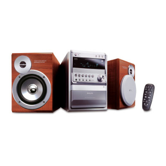
Micro System
Service
Service
Service
Service
Service
Service Manual
©
Copyright 2005 Philips Consumer Electronics B.V. Eindhoven, The Netherlands
All rights reserved. No part of this publication may be reproduced, stored in a retrieval system or
transmitted, in any form or by any means, electronic, mechanical, photocopying, or otherwise
without the prior permission of Philips.
Published by SL 0535 Service Audio
Version 1.0
TABLE OF CONTENTS
Location of pc boards & Version variations ................ 1-2
Technical Specifications ............................................. 1-3
Measurement setup .................................................... 1-4
Service Aids, Safety Instruction, etc. ............... 1-5 to 1-6
Lead-free Information & Service Instruction .............. 1-7
Preparations & Controls & Troubleshooting .. 1-8 to 1-10
Disassembly Instructions & Service positions .............. 2
Service Test Programs ............................................... 3-1
Set Block diagram ...................................................... 4-1
Set Wiring diagram ..................................................... 5-1
Front Board (MCU Board) ............................................. 6
Tuner Board (ECO Non Cenelec) .............................. 7A
Tuner Board (ECO Cenelec) ...................................... 7B
Main Board .................................................................... 8
Cassette Board .............................................................. 9
CD & MP3-CD2002 Board ........................................... 10
Rectifier Board ............................................................. 11
Set Mechanical Exploded view & parts list ................. 12
Printed in The Netherlands
Subject to modification
MCM510
Page
CLASS 1
LASER PRODUCT
GB
/22/25/33
COMPACT
DIGITAL AUDIO
3141 785 30540
Advertisement
Table of Contents

Subscribe to Our Youtube Channel
Related Manuals for Philips MCM510/22/25/33


Summary of Contents for Philips MCM510/22/25/33
- Page 1 LASER PRODUCT © Copyright 2005 Philips Consumer Electronics B.V. Eindhoven, The Netherlands All rights reserved. No part of this publication may be reproduced, stored in a retrieval system or transmitted, in any form or by any means, electronic, mechanical, photocopying, or otherwise without the prior permission of Philips.
-
Page 2: Location Of Pcbs
LOCATION OF PCBS VERSION VARIATIONS: Type /Versions: MCM510 Features & Board in used: Aux in / CDR in Line Out Video Out Surround Out Subwoofer Out Power Booster Out Digital Out Digital in Matrix Surround News Dolby Pro Logic (DPL) Incredible Surround Karaoke Features Voltage Selector... -
Page 3: Specifications
SPECIFICATIONS AMPLIFIER: GENERAL: Mains voltage : 230V ± 10% for /22/25 Output power 220V ± 10% for /33 L & R : 2 x 25W (4Ω, 1kHz, 10% THD) Frequency response within -3dB : 60Hz-14kHz Mains frequency : 50/60Hz Digital Sound Control (DSC) : Jazz / Rock / Pop / Classic Clock accuracy : <... -
Page 4: Measurement Setup
MEASUREMENT SETUP Tuner FM Bandpass LF Voltmeter 250Hz-15kHz e.g. PM2534 e.g. 7122 707 48001 RF Generator e.g. PM5326 S/N and distortion meter e.g. Sound Technology ST1700B Use a bandpass filter to eliminate hum (50Hz, 100Hz) and disturbance from the pilottone (19kHz, 38kHz). Tuner AM (MW,LW) Bandpass LF Voltmeter... -
Page 5: Service Aids
SERVICE AIDS Service Tools: ESD Equipment: Universal Torx driver holder ........4822 395 91019 Anti-static table mat - large 1200x650x1.25mm ... 4822 466 10953 Torx bit T10 150mm ..........4822 395 50456 Anti-static table mat - small 600x650x1.25mm ..4822 466 10958 Torx driver set T6 - T20 ......... -
Page 6: Class 1 Laser Product
WAARSCHUWING WARNING Alle IC’s en vele andere halfgeleiders zijn All ICs and many other semi-conductors are gevoelig voor electrostatische ontladingen susceptible to electrostatic discharges (ESD). (ESD). Careless handling during repair can reduce life Onzorgvuldig behandelen tijdens reparatie kan drastically. de levensduur drastisch doen verminderen. When repairing, make sure that you are Zorg ervoor dat u tijdens reparatie via een connected with the same potential as the mass... -
Page 7: Information About Lead-Free Soldering
To avoid wear-out of tips switch off un-used equipment, or reduce heat. • Mix of lead-free solder alloy / parts with leaded solder alloy / parts is possible but PHILIPS recommends strongly to avoid mixed solder alloy types (leaded and lead-free). -
Page 8: Preparations And Controls
PREPARATIONS AND CONTROLS... - Page 9 PREPARATIONS AND CONTROLS...
- Page 10 1-10...
-
Page 11: Dismantling Instructions
DISMANTLING INSTRUCTIONS Dismantling of the Cover Cassette and Universal Loader Detaching the Front Panel assembly from the Bottom/Rear assembly 1) Push 1 catch each on the left & right side then remove the Cover Cassette in the direction as shown in Figure 1 and Figure 1A. - Page 12 DISMANTLING INSTRUCTIONS Dismantling of the Front Panel assembly Dismantling of the Rear Panel assembly 4) Loosen 1 scew N and 2 catches C6 (see Figure 8) to 1) Loosen 3 screws K and 2 catches C5 (see Figure 8) to remove the Tuner Board assembly.
- Page 13 DISMANTLING INSTRUCTIONS Repair Hints & Service Positions Service position B 1) During repair it is possible to disconnect the Tuner Board Note: The flex cables are very fragile, care should be taken and/or CD Module completely unless the fault is sus- not to damage them during repair.
-
Page 14: Service Test Program
SERVICE TEST PROGRAM To enter Service * Door switch is ignored → CD door can be opened. Testprogram hold * Tuner test the sound settings Volume up/down, PLAY & DISPLAY buttons DSC, IS and DBB function as in normal mode, depressed while but flags will not be indicated on the display in all steps. -
Page 15: Set Block Diagram
SET BLOCK DIAGRAM... -
Page 16: Set Wiring Diagram
SET WIRING DIAGRAM Front PCB... -
Page 17: Layout Diagram - Headphone Board
LAYOUT DIAGRAM - HEADPHONE BOARD FRONT BOARD TABLE OF CONTENTS Headphone Board Layout ..........6-1 Front Board Layout Top View .......... 6-2 Front Board Layout Bottom View ........6-3 Circuit Diagram ..............6-4 Electrical Parts List ............6-5... - Page 18 LAYOUT DIAGRAM - FRONT BOARD TOP SIDE...
- Page 19 LAYOUT DIAGRAM - FRONT BOARD BOTTOM SIDE...
-
Page 20: Circuit Diagram - Front Board
CIRCUIT DIAGRAM - FRONT BOARD /22/25... - Page 21 ELECTRICAL PARTS - FRONT BOARD EN701 9940 000 03211 ENCODER IC701 9940 000 03213 IC OTP TMP86PS25F IC702 9940 000 03272 IC M24C01-RDW6T IC703 9940 000 03215 RDS IC SAA6581T IC704 9940 000 03214 VFD DRIVER IC PT6315 L703 9940 000 03216 CHOKE COIL 100µH L705 9965 000 17286...
- Page 22 7A-1 7A-1 BLOCK DIAGRAM TUNER BOARD ECO 6 Systems Vcc1 buffer ampl. Stab Stab Discriminator FM-RF FM-IF 1 FM-IF 2 (MPX) Vcc2 1101 Loop (1102) LF filter 10,7 MHz 10,7 MHz 10,7 MHz 1120 left left Stereo right right Det. Decoder Frontend Mixer...
-
Page 23: Tuner Board Eco6 / Systems Non Cenelec
7A-2 7A-2 1101 A1 1102 B1 1103 F2 1120 E14 1130 A2 TUNER BOARD ECO6 1131 B2 / SYSTEMS NON CENELEC 1132 G13 2101 B3 VERSION PROGRAMMING COMPONENTS 2102 B1 1101 2103 C7 2105 2104 B3 AM-IF1 1130 2105 A2 100n 5111 450kHz... -
Page 24: Tuner Adjustment Table
7A-3 7A-3 1101 A6 1120 A4 1132 A5 2128 C4 2138 C2 3142 D2 5110 B3 5114 A2 5123 D5 7112 C1 9104 B5 9107 D4 TUNER ADJUSTMENT TABLE ( ECO6 FM/MW- and FM/MW/LW - versions with AM-frame aerial ) 1102 B6 1130 B5 2106 C5... -
Page 25: Integrated Circuits
7A-4 7A-4 Electrical Partslist ECO6 SYSTEMS NON CENELEC MISCELLANEOUS RESISTORS ––––––––––––––––––––––––––––––––––––––––––––––––––––– ––––––––––––––––––––––––––––––––––––––––––––––––––––– 1101 2422 015 19376 SOCKET 2P CLICKFIT 3143 © 4822 051 20223 22kΩ 0,1W USA only RDS only 1102 4822 267 10283 SOCKET COAX, IEC 75Ω 3144 © 4822 051 10102 1kΩ... - Page 26 7B-1 7B-1 BLOCK DIAGRAM ECO6 Tuner Board SYSTEMS CENELEC version: TABLE OF CONTENTS Blockdiagram..............7B-1 Schematic Diagram............7B-2 Component Layout ............7B-3 Adjustment table .............7B-3 Electrical Partslist............7B-4...
-
Page 27: Tuner Board Eco6
7B-2 7B-2 1101 A2 5121 E11 1102 B1 5122 H5 1103 E2 5123 G5 1110 B2 6105-1 E4 VERSION PROGRAMMING COMPONENTS 1120 E14 6105-2 G6 TUNER BOARD ECO6 1130 A2 6106 D4 / SYSTEMS-CENELEC 1131 C2 6107 G13 VERSION AM-IF1 1132 F13 6120 C13 6120... -
Page 28: Tuner Board Eco6 Systems - Cenelec
7B-3 7B-3 1101 B5 1110 B4 1131 C5 2107 B3 2133 C1 2162 A4 5102 C4 5110 A2 5114 A2 5121 B2 7104 C4 9101 A2 9104 B1 9107 B4 9110 A4 TUNER ADJUSTMENT TABLE ( ECO6 Cenelec FM/MW - and FM/MW/LW - versions with AM-frame aerial ) 1102 B5 1120 A4 1132 A4... - Page 29 7B-4 7B-4 Electrical Partslist ECO6 SYSTEMS CENELEC MISCELLANEOUS RESISTORS DIODES ––––––––––––––––––––––––––––––––––––––––––––––––––––– ––––––––––––––––––––––––––––––––––––––––––––––––––––– ––––––––––––––––––––––––––––––––––––––––––––––––––––– 1101 2422 015 19376 SOCKET CLICKFIT 2P 3128 © 4822 117 11449 2,2kΩ 0,1W 6105 © 4822 130 83075 HN1V02H USA only LW only 1102 4822 267 10283 SOCKET COAX, IEC 75Ω...
-
Page 30: Main Board
BLOCK DIAGRAM - 4-CHANNEL AUDIO AMPLIFIER TDA8947J MAIN BOARD BLOCK DIAGRAM - 4-CHANNEL MULTIPLEXER TC4052B TABLE OF CONTENTS Internal IC Diagram ............8-1 Main Board Layout Top View ........... 8-2 Main Board Layout Bottom View ........8-3 Circuit Diagram - MCU Part ..........8-4 Electrical Parts List ............ - Page 31 LAYOUT DIAGRAM - MAIN BOARD TOP SIDE...
- Page 32 LAYOUT DIAGRAM - MAIN BOARD BOTTOM SIDE...
-
Page 33: Circuit Diagram - Main Board
CIRCUIT DIAGRAM - MAIN BOARD... - Page 34 ELECTRICAL PARTS - MAIN BOARD CON405 9940 000 03196 8.3MM RCA JACK CON601 9940 000 03197 PUSH TERMINAL JACK IC201 9940 000 01435 IC S7805P IC401 9940 000 03199 IC HEF4094BT IC402 9940 000 03201 IC TC4052BF SWITCHING IC501 9940 000 03198 IC HEF4069UBT IC601 9940 000 03203...
-
Page 35: Circuit Diagram - Cassette Board
9 - 1 9 - 1 CIRCUIT DIAGRAM - CASSETTE BOARD... - Page 36 9 - 2 9 - 2 LAYOUT DIAGRAM - CASSETTE BOARD COMPONENT SIDE COPPER SIDE...
- Page 37 9 - 3 9 - 3 TAPE ADJUSTMENT & CHECK TABLE ADJUST TEST RECORDER MEASURE READ ON CASSETTE MODE with SBC420 frequency PLAY check 3150Hz +/- 2% MOTOR SPEED counter 3150Hz SBC420 check PLAY W&F-meter < 0.4 % DIN WOW & FLUTTER 3150Hz PLAY FWD left hand screw...
- Page 38 10 - 1 10 - 1 CIRCUIT DIAGRAM - CD BOARD (PART 1)
- Page 39 10 - 2 10 - 2 CIRCUIT DIAGRAM - CD BOARD (PART 2)
-
Page 40: Layout Diagram - Cd Board
10 - 3 10 - 3 LAYOUT DIAGRAM - CD BOARD COMPONENT SIDE COPPER SIDE Mapping Chip Components 2811 A5 3845 B3 2813 C1 3846 C2 2814 D2 3847 B3 CD99 - MP3CD2002 Board Copperside view CD99 - MP3CD2002 Board Componentside view 2815 C2 3848 B2 2816 C2... - Page 41 10 - 4 10 - 4 CIRCUIT DIAGRAM - MP3CD2002 BOARD (For reference only) MP3-CD-2002 2451 B5 F425 I13 2452 B2 F426 I13 2453 B4 F427 E8 2454 B7 F428 E8 only for FLASH version 2455 C2 F429 E8 2456 C12 F430 F8 2457 D9 F432 F8...
- Page 42 10 - 5 10 - 5 LAYOUT DIAGRAM - MP3CD2002 BOARD (For reference only) 3469 C4 3479 A2 4450 A4 1460 A3 3449 C3 3460 C2 3482 B2 3492 A3 6450 C2 1451 B5 2457 A2 2469 B4 3493 B2 7450 B4 1455 A4 2461 D4...
-
Page 43: Rectifier Board
11-1 11-1 RECTIFIER BOARD TABLE OF CONTENTS Layout Top View .............. 8-2 Layout Bottom View ............8-2 Circuit Diagram ..............8-3 Electrical Parts List ............8-4... - Page 44 11-2 11-2 LAYOUT DIAGRAM - RECTIFIER BOARD LAYOUT DIAGRAM - RECTIFIER BOARD TOP SIDE BOTTOM SIDE...
- Page 45 11-3 11-3 CIRCUIT DIAGRAM - RECTIFIER BOARD...
- Page 46 11-4 11-4 ELECTRICAL PARTS - RECTIFIER BOARD C109 9940 000 03218 ELE. CAPACITOR 4700µF 35V C110 9940 000 03218 ELE. CAPACITOR 4700µF 35V C115 9940 000 03217 ELE.CAP 3300µF 25V D100 9940 000 03223 BRIDGE RECTIFIER GBU6B F101 9940 000 01447 FUSE 2.5A 250V D5X20MM F102 9940 000 03224...
- Page 47 12-1 12-1...
- Page 48 12-2 12-2 MECHANICAL & ACCESSORIES PARTS ELECTRICAL PARTS - MISCELLANEOUS 9940 000 03236 TOP CABINET 9940 000 03266 SPEAKER BOX ASSY /22/25 CON803 9940 000 03229 HEADPHONE JACK D3.5MM 9940 000 03249 CD DOOR 9940 000 03282 SPEAKER BOX ASSY /33 JACK1 9940 000 01458 FM 75Ω...
Need help?
Do you have a question about the MCM510/22/25/33 and is the answer not in the manual?
Questions and answers