
Summary of Contents for DIVEX MHE-02
- Page 1 INSTALLATION, OPERATING AND MAINTENANCE MANUAL for the Mini Water Heater Electric Model: MHE-02 (440 VAC Supply x 24 VDC Controls) Document No: KI-OM-523 Legacy No: 05984-805 (Part No: KI40026AA...
- Page 2 (Intentionally Blank)
- Page 3 APPROVAL SHEET DIVEX DOCUMENT NUMBER: KI-OM-523 LEGACY NUMBER: 05984-805 DOCUMENT TITLE: Installation, Operating and Maintenance Manual - MHE-02, 440 VAC Supply x 24 VDC Controls DATE CHECK COMMENTS 31/03/2010 R. Carli N. Maske R. Faustmann First Issue 11/06/2010 R. Carli N.
- Page 4 (Intentionally Blank) Approval Sheet KI-OM-523 R2...
-
Page 5: Table Of Contents
TABLE OF CONTENTS Data Sheet ..........................v Disclaimer ..........................vii Confidential Information ......................ix Warranty ..........................xi List of Tables and Figures ....................xiii CHAPTER 1 - GENERAL DESCRIPTION ..................1 Introduction ..........................1 1.1.1 Basic Description ........................1 Specifications ......................... 1 Theory of Operation ....................... - Page 6 CHAPTER 4 - MAINTENANCE ....................23 Routine Maintenance ......................23 4.1.1 Periodic Maintenance ......................23 Pump Maintenance ......................24 4.2.1 Helpful Information ....................... 24 4.2.2 Pump Specifications ......................25 CHAPTER 5 - TROUBLESHOOTING ..................27 Pump Specific Fault Diagnosis and Maintenance ..............27 General Troubleshooting Chart ....................
-
Page 7: Ii. Data Sheet
Mini Water Heater Electric - MHE-02 (440V x 24V) ………………………………………………… EQUIPMENT SERIAL NO: ………………………………………………… CUSTOMER: ………………………………………………… VESSEL / LOCATION: (IF KNOWN) ………………………………………………… DATE OF ISSUE: ………………………………………………… IMPORTANT Please quote the above information when contacting Divex regarding operational information or spare parts. KI-OM-523 R2 Data Sheet... - Page 8 (Intentionally Blank) Data Sheet KI-OM-523 R2...
-
Page 9: Iii. Disclaimer
III. DISCLAIMER Whilst every effort has been made to ensure the accuracy of the information provided in this document, Divex makes no guarantees therefore. Misuse of the equipment described in this manual could result in injury. It is the responsibility... - Page 10 (Intentionally Blank) viii Disclaimer KI-OM-523 R2...
-
Page 11: Iv. Confidential Information
IV. CONFIDENTIAL INFORMATION This document is confidential and is the property of Divex It may not be distributed to persons or organizations other than the intended recipient without the prior written consent of the owner KI-OM-523 R2 Confidential Information... - Page 12 (Intentionally Blank) Confidential Information KI-OM-523 R2...
-
Page 13: Warranty
V. WARRANTY Divex Ltd warrants that its Mini Water Heater Electric (Type MHE-02), conforms to the current product specification at the date of delivery and that the product will be free of patent defects in materials or workmanship for a period of twelve months from the date of delivery or for the first 3,000 operating hours, whichever occurs first. - Page 14 (Intentionally Blank) Warranty KI-OM-523 R2...
-
Page 15: Vi. List Of Tables And Figures
Graph of Temperature Loss vs. Umbilical Length ............18 Fig 3.2 General Arrangement ....................20 Fig A.1 MHE-02 General Arrangement - Isometric View ............35 Fig A.2 MHE-02 General Arrangement - Side View ............... 36 Fig A.3 MHE-02 General Arrangement – Front View ............. 38 Table 1.1 Heater Component Identification .................. - Page 16 (Intentionally Blank) List of Tables and Figures KI-OM-523 R2...
-
Page 17: Chapter 1 General Description
1.1.1 BASIC DESCRIPTION The MHE-02 assembly Includes a motor, pump, heater tank, pipework and a control panel. These components are mounted into a robust stainless steel frame. The system requires a constant supply of sea water and runs from a 440-480V, 3-phase, 60 Hz power supply. The output is heated sea water at pressures up to 68 bar and 30 litres/min. -
Page 18: Theory Of Operation
1.3.1 BASIC CONTROL The temperature control system of the MHE-02 has been designed to be simple and effective. The unit heats water in the heater tank using three banks of heater elements. These heater banks are controlled with three switches, mounted on the electrical enclosure. -
Page 19: Fluid System
1.3.2 FLUID SYSTEM The MHE-02 may function with either salt water or fresh water as the heating medium. The unit is provided with two inlets for fluid, one for fresh water and one for sea water. The fresh water line is typically used for flushing the system after use. The freshwater line is fitted with a check valve to prevent salt water contamination of the fresh water supply. -
Page 20: Fig 1.1 Mhe-02 Fluid Connections
The outlet manifold is fitted with both pressure and temperature gauges to provide operator feedback. A full flow diagram and system drawings are provided in the Appendix. Fig 1.1 MHE-02 Fluid Connections Chapter 1 KI-OM-523 R2... -
Page 21: Electrical System Overview
1.3.3 ELECTRICAL SYSTEM OVERVIEW The MHE-02 electrical system is comprised of a 440 VAC power circuit and a 24 VDC control circuit. The power circuit is the electrical supply for the heaters, pump motor and DC power supply unit. The control circuit provides power supply to all control, indication and safety circuits. -
Page 22: Heater System And Heater Selection
1.3.5 HEATER SYSTEM AND HEATER SELECTION The heaters are arranged into heater banks comprised of groups of heater elements. Each heater bank is controlled by a switch mounted in the control panel. The switch supplies 24V to the coil of the contactor/s of the relevant bank. The following table shows the control structure of the heater banks and the composition of the heater groups. -
Page 23: Control System
1.3.6 CONTROL SYSTEM The 24 VDC control circuit is used to control the contactors, relays, timer and the safety circuits in the system. The contactors, controlled by switches mounted in the control panel door, switch the high voltage to the heaters and the pump. The temperature of the output fluid is regulated by dumping excess capacity thereby increasing the flow rate of fluid through the heater tank and lowering the output temperature of the fluid outlet. - Page 24 The following table identifies the major control components, and outlines their function within the control circuit. COMPONENT COMPONENT ID FUNCTION DESCRIPTION Contactor 1 Pump contactor coil Contactor 2-5 C2-C5 Heater contactor coils Hour Meter The hour meter records the running hours of the pump and is wired through the auxiliary contact on the pump contactor C1/1.
- Page 25 COMPONENT COMPONENT ID FUNCTION DESCRIPTION Pump Overload O/L1 This overload trips if the pump draws a current of over 12 Amps. The normally open contact of the overload supplies the pump run indication. The normally closed contact of the overload is used in the safety circuit.
- Page 26 COMPONENT COMPONENT ID FUNCTION DESCRIPTION Switch Rotary S3, S4 & S5 The two position heater ON/OFF switches control the switching of the power to the coils of Heater Selection the respective heater contactors C1-C5. (See Table 3.1). Switch This switch contact de-energizes the motor and Mushroom heater control circuits.
-
Page 27: Chapter 2 Initial Set Up
0.5 to 1 m for service and maintenance. 2.1.2 FLUID CONNECTIONS The MHE-02 requires both salt and fresh water supply with a minimum flow rate of 30 lit/min at 3 bar. NOTE This is the minimum required for Cat pump supply, up to approximately another 30 ltr/min may be required for adequate temperature control). -
Page 28: Electrical Installation
CAUTION DUMP LINE RESTRICTION To ensure correct machine operation, the dump line should never restrict flow of dumped water. The 1″ dump pipe may be connected to any water dump system that has minimal back pressure. The volume of water being dumped during manual and/or automatic control may vary however in the event of complete restriction of the hot water outlet line and the resultant rise of the outlet pressure above the relief pressure the full flow will have to be dumped via the relief valve. -
Page 29: Start Up And Function Check
To complete priming shut the vent valve and supply valve(s). 2.2.2 START UP AND FUNCTION CHECK After installation is complete the MHE-02 must be thoroughly checked prior to being put into service. The following procedure outlines the steps used in conducting a comprehensive start-up and functional check. - Page 30 Pump Oil Level - Check the oil level in the pump crankcase (level with dot on sight glass). Pump Rotation - To check the rotational direction of the motor push the start button and then stop button. This will momentarily power the pump motor. Confirm the correct rotation of the pump as indicated by the rotation arrows on the both sides of the pump.
-
Page 31: Fig 2.1 Controller Display
Fig 2.1 Controller Display Fill Umbilical – Connect umbilical to HP water outlet port and open the salt water inlet valve. Allow water to flow through the system until it flows out of the umbilical. Salt water or fresh water may be used depending upon which is available. Pump Motor Start - Push the pump Start button, the pump will start running and system pressure will rise to balance the pressure drop down the length of umbilical. - Page 32 should be regularly checked after set-up. Replace the filter elements (DSA Part No. 04793) when the pressure drop rises above 1.2 bar. Current Drawn - Check input current and voltage to make sure acceptable limits are maintained. Process Control - When the unit is set-up and operating properly with the correct heater selection and supplies it will deliver water heated to within ±...
-
Page 33: Chapter 3 Operation
CHAPTER 3 OPERATION GENERAL The Divex Electric Powered Mini Water Heating Module has been designed to run with the minimum amount of operator input. The temperature controller governs the process based on the set point and feedback from the PT100 probe giving the measured output temperature (PV). -
Page 34: Fig 3.1 Graph Of Temperature Loss Vs. Umbilical Length
Fig 3.1 Graph of Temperature Loss vs. Umbilical Length NOTE The above graph is based on the approximate temperature loss through a ½” Synflex or equivalent, used in conditions with 2-5°C (35-45°F) water temperature. Step 2 - Determine temperature rise required. To determine the required temperature rise (T through the unit subtract the inlet rise) - Page 35 380 VOLT TEMP HEATER ON (●) RISE ºC ºF HEATER 1 HEATER 2 HEATER 3 (0-9) ● 13.5 5-10 (9-18) ● 27.0 10-15 (18-27) ● ● 40.5 15-22 (27-39) ● 54.0 22-29 (39-51) ● ● 67.5 29-35 (51-62) ● ● 81.0 35-42 (62-74)
-
Page 36: Operator Controls
3.1.1 OPERATOR CONTROLS Operator control of the MHE-02 is achieved using the controller keypad to change the set point and switches for heater bank selection. The MHE-02 is also equipped with several analogue gauges displaying fluid temperature and pressure throughout the system. The layout of the operator interface is shown in Fig 1.2. -
Page 37: Operating Start-Up Procedure
3.1.2 OPERATING START-UP PROCEDURE Pre-operation checks should be done on the following: • Machinery is secure – No damage to mountings, brackets, pipe connections etc. • Belt drive – In a good condition, belts correctly tensioned and belt guard secure. •... -
Page 38: Shutdown Procedure
3.1.3 SHUTDOWN PROCEDURE Turn off all electric heaters. Push Pump Stop Button. Turn off main power switch. Shut sea water valve and open fresh water valve to flush the entire system with fresh water for at least 15 to 20 minutes after each usage. This will flush out the heating system, plumbing, valves, umbilical and most important, the breathing gas heat exchanger and the hot water suit. -
Page 39: Chapter 4 Maintenance
Heater Elements – Heater element cover plates should be removed to check for leaks and, if necessary, check element insulation. To remove any elements use WHE-03 element socket, Divex part no. 05547. IMPORTANT Heated sea water is extremely corrosive and heater elements will not last indefinitely. -
Page 40: Pump Maintenance
Shut-off valves in the inlet or discharge plumbing to be sure they are fully open Pump Service – Divex advises that the service of the CAT pump on the MHE-02 unit should be carried out by an approved CAT service agent or Divex regional office. -
Page 41: Pump Specifications
4.2.2 PUMP SPECIFICATIONS MHE-02 SETUP SPECIFICATION Flow Rate (Max) 30 l/min 45 l/min [Max] Pressure Range 7 to 155 bar 7 to 155 bar Inlet Pressure Range 1.4 to 4 bar 1.4 to 4 bar Speed (Maximum Allowable) 767 rev/min... - Page 42 (Intentionally Blank) Chapter 4 KI-OM-523 R2...
-
Page 43: Chapter 5 Troubleshooting
CHAPTER 5 TROUBLESHOOTING The tables in this section are designed as a troubleshooting guide to aid in the identification of faults and outline possible corrective action. PUMP SPECIFIC FAULT DIAGNOSIS AND MAINTENANCE PROBLEM POSSIBLE CAUSE SOLUTION Pulsation Faulty Pulsation Damper. Check pre-charge of pulsation Damper;... - Page 44 Water in crankcase May be caused by humid air Change oil at 3 month or 500 condensing into water inside hour intervals using Divex part the crankcase. no. DO03764. Leakage of packing seals. Replace packing. Check Over-pressure or faulty pressure regulator.
-
Page 45: General Troubleshooting Chart
PROBLEM POSSIBLE CAUSE SOLUTION Strong surging at Foreign particles in the inlet or Check for smooth lap surfaces inlet and low discharge valve or worn inlet on inlet and discharge valve pressure on and/or discharge valves. seals. Discharge valve seals discharge side and inlet valve seals may be lapped on a very fine oil stone. - Page 46 PROBLEM POSSIBLE CAUSE SOLUTION Motor fault - will Fault in wiring to Trace wiring; make sure there is no not run contactor, control circuit broken circuit to wiring. If there is, or main control circuit is correct malfunction. If main power broken.
- Page 47 PROBLEM POSSIBLE CAUSE SOLUTION Large flow in Leaking relief valve. Clean relief valve and reset. If valve overboard dump continues to leak, replace. line Large flow in Overboard dump valve Close valve. overboard dump left open. line Too many heaters on for Refer to table to determine proper load on system.
- Page 48 PROBLEM POSSIBLE CAUSE SOLUTION Water Insufficient number of Turn on one additional heater. Check temperature will heaters on for load. Heater Selection Table 3.1. not rise adequately Contactors Dirt, debris or rust on Disassemble contactor and sand pole buzzing pole pieces of pieces and clean.
- Page 49 PROBLEM POSSIBLE CAUSE SOLUTION Contactors will Faulty contactor. Replace. not open Shorted wire on holding Check out wiring for short and repair. coil. System Burned out fault light. Replace. inoperable, no Faulty fault relays, R1 Replace. fault indicator and R2. No 24 VDC Control transformer Check output of power supply.
- Page 50 (Intentionally Blank) Chapter 5 KI-OM-523 R2...
-
Page 51: Appendix A Part Identification
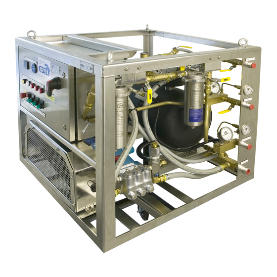
APPENDIX A PART IDENTIFICATION Fig A.1 MHE-02 General Arrangement - Isometric View ITEM DESCRIPTION DIVEX PART NO. Control Panel HP Hose Assembly DO 06035 Ball Valve, ½” NPT, (Heater Tank Bleed Valve) XV500P-8-02 Ball Valve, ¾”, Brass, (Fresh Water Inlet Shut-off Valve) XV500P-12-02 Check Valve ¾”... -
Page 52: Fig A.2 Mhe-02 General Arrangement - Side View
Fig A.2 MHE-02 General Arrangement - Side View ITEM DESCRIPTION DIVEX PART NO. Pressure Reducing Valve 5360 ¾ DO 02359 Ball Valve ¾” NPT, (Filter Isolation Valves) XV500P-12-02 Ball Valve ¾” NPT, (Filter Isolation Valves) XV500P-12-02 μ Filter Housing ¾” NPT, (With 50 DO 04768 Filter Element DSA No. - Page 53 ITEM DESCRIPTION DIVEX PART NO. Gauge Pressure 0-10 bar Back Entry (Inlet Water Pressure Gauge) PBBV63BB02QJ2A Sea Water Inlet Connection ¾” NPT Gauge, Temp., 0-100°C Swivel Brkt. (Inlet Water Temperature Gauge) DO 06068 Gauge Pressure 0-100 bar Back Entry (Outlet Water Pressure Gauge) PBBV63BB02QJ3A Hot Water Outlet Connection ¾”...
-
Page 54: Fig A.3 Mhe-02 General Arrangement - Front View
Fig A.3 MHE-02 General Arrangement – Front View ITEM DESCRIPTION DIVEX PART NO. Hour Meter 10-80VDC DO 03903 Controller Temperature RKC DO 03900 Control Power On Indication Lamp DO 04991 Fault Reset Push Button DO 04838 + DO 02889 + DO 02889... -
Page 55: Appendix B Recommended Spare Parts List & Acquisition Form
APPENDIX B RECOMMENDED SPARE PARTS LIST & ACQUISITION FORM RECOMMENDED SPARE PARTS LIST - (SPARES KIT - KI40026AA-KIT) DESCRIPTION DIVEX SA PART SHOWN AS HP Hose Assembly DO 06035 Item 2, Fig A.1 Valve Ball, ½” NPT Brass XV500P-8-02 Item 3, Fig A.1 Valve Ball, ¾”NPT, Brass... - Page 56 DO 02760 Valve Relief ½”MNPT 3-50 PSI Brass DO 02304 Valve Globe ¾”NPT Brass DO 03326 Oil Divex CAT Pump Lubeb [litres] DO 03764 Circuit Breaker Miniature 50A 6kA 3pole DO 05934 Circuit Breaker Miniature 20A 6kA 3pole DO 05932...
-
Page 57: Recommended Spare Parts - (Not In Spares Kit Ki040026Aa - Kit)
RECOMMENDED SPARE PARTS – (NOT IN SPARES KIT KI040026AA - KIT) DESCRIPTION DIVEX SA PART SHOWN AS Label Heater Selection MHE-02 DO 06055 Manifold MHE-2 Sea Water In CZ121 DO 05955 Item 6, Fig A.1 Manifold MHE-2 Hot Water CZ121 DO 05957 Item 8, Fig A.1... - Page 58 (Intentionally Blank) APPENDIX B KI-OM-523 R2...
-
Page 59: Appendix C Spares Acquisition Sheet
Order No: appropriate) NOTE Please attach full contact details to this sheet when placing orders and fill in required quantities in the table below before faxing or e-mailing this request to the nearest Divex office for attention. DESCRIPTION DIVEX SA... - Page 60 DESCRIPTION DIVEX SA DESCRIPTION DIVEX SA PART NO. PART NO. Gauge Pressure 0-10 PBBV63BB02 Relay Miniature 24VDC DO 04171 bar Back Entry QJ2A Coil 4 C/O Gauge Pressure 0-100 PBBV63BB02 Module Diode Plug-In DO 03910 bar Back Entry QJ3A 6 - 220 VDC...
-
Page 61: Appendix D Wiring Diagrams
APPENDIX D WIRING DIAGRAMS KI-OM-523 R2 APPENDIX D... -
Page 65: Appendix E Piping And Flow Schematic
APPENDIX E PIPING AND FLOW SCHEMATIC KI-OM-523 R2 APPENDIX E... -
Page 67: Appendix F Rkc Cb100 Digital Controller Manual
APPENDIX F RKC CB100 DIGITAL CONTROLLER MANUAL KI-OM-523 R2 APPENDIX F... -
Page 80: Appendix G Belimo Control Valve Manual
APPENDIX G BELIMO CONTROL VALVE MANUAL KI-OM-523 R2 APPENDIX G... -
Page 87: Appendix H Water Pressure Reducing Valve
APPENDIX H WATER PRESSURE REDUCING VALVE KI-OM-523 R2 APPENDIX H... -
Page 94: Appendix I Cat Triplex Pump - Manual - Model 1050
APPENDIX I CAT TRIPLEX PUMP - MANUAL - MODEL 1050 KI-OM-523 R2 APPENDIX I... -
Page 107: Appendix J Pulsation Dampener
APPENDIX J PULSATION DAMPENER KI-OM-523 R2 APPENDIX J... -
Page 110: Appendix K Pressure Regulator
APPENDIX K PRESSURE REGULATOR KI-OM-523 R2 APPENDIX K... -
Page 115: Appendix L Float Switch
APPENDIX L FLOAT SWITCH KI-OM-523 R2 APPENDIX L...
Need help?
Do you have a question about the MHE-02 and is the answer not in the manual?
Questions and answers