Table of Contents
Advertisement
Quick Links
- 1 Brief Introduction and Spectrapro-300I Description
- 2 Specifications
- 3 Connecting the Spectrapro-300I to the Optional 300-749
- 4 Spectrapro-300I Setup
- 5 Mounting Accessories
- 6 Operating the Spectrapro-300I Using a Computer
- 7 Focusing and Aligning CCD Array Detectors
- 8 Changing from Monochromator to Spectrograph Operation
- Download this manual
Advertisement
Table of Contents

Summary of Contents for ACTON SpectraPro-300i
-
Page 1: Operating Instructions
530 Main Street, Acton, MA 01720 Phone: (978)263-3584, Fax: (978)263-5086 Web Site: www.acton-research.com Operating Instructions Acton Research Corporation SpectraPro-300i 0.300 Meter Focal Length Triple Grating Imaging Monochromator / Spectrograph SP-300i Manual Rev. 997.1... -
Page 2: Table Of Contents
Page Brief Introduction and SpectraPro-300i Description Specifications III. SpectraPro-300i Setup Unpacking Note Connecting the SpectraPro-300i to the Optional 300-749 Remote Scan Controller, or to a Computer Cables and Connections for SpectraPro-300i Mounting Accessories Mounting Focal Plane Detectors 6 - 7... -
Page 3: Brief Introduction And Spectrapro-300I Description
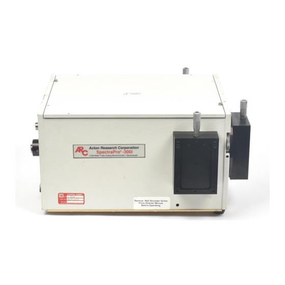
I: Brief Introduction and SpectraPro-300i Description Brief Introduction: This instruction manual is intended to assist you in set-up and operation of your new SpectraPro-300i monochromator/spectrograph. Even if you are an experienced user of spectroscopic equipment, we suggest that you follow the manual (at least initially) to insure proper setup and operation. If you have any questions about the information contained in this manual, please feel free to contact the ARC customer service department. -
Page 4: Specifications
II: SpectraPro-300i Specifications NOTE: Each SpectraPro-300i is operated for at least 15 minutes prior to calibration to insure optimum stability. End users should follow this practice if their application calls for optimum stability & reproducibility. Specifications (1200g/mm Grating) Every SpectraPro-300i monochromator or spectrograph... -
Page 5: Spectrapro-300I Setup
Section III-B: Connecting the SpectraPro-300i Monochromator/Spectrograph to the Optional Model 300-749 Remote Scan Controller or Computer The SpectraPro-300i is designed for operation by computer using RS232 or IEEE488, or by using the optional Model 300-749 Remote Scan Controller. Either method of control enables wavelength scanning at a pre-set linear scan rate, change of scanning speeds, grating selection, rapid GOTO wavelength positioning, change of grating turrets if available, and “jog”... -
Page 6: Cables And Connections For Spectrapro-300I
CC-499-5 IEEE488 cable, 4 meters long The cable CC-499-2 is included with the SpectraPro-300i. The other cables are optional. If none of these cables are compatible with your system, consult ARC for a custom cable. If you have facilities for constructing a custom cable, use the RS232 pin arrangement shown in Table 1, or the IEEE488 pin arrangement shown in Table 2. -
Page 7: Mounting Accessories
Accessories: The full range of ARC SpectraPro accessories mount directly to the SpectraPro-300i slit assemblies. A drawing of the standard slit assembly can be found in the Appendices Section to assist you in mounting of accessories. To mount an accessory to the slit, the general procedure is as follows: Place the accessory directly against the face of the slit body. - Page 8 Gently slide the array detector mounting flange all the way out of the SpectraPro-300i housing. Make sure that the sliding tube and o-ring are kept clean. Remove the shipping cover from the sliding tube, and the spacer if not required.
- Page 9 Section III-F: Slit Width Adjustments in the Model 716 Bilateral Slits The slit width of each bilateral slit assembly (716 type) is adjustable from 0.010 millimeters to 3 millimeters (10µm to 3,000µm) by a micrometer located on the top of the slit housing. The micrometer knob is graduated in 0.010 millimeter (10µm) increments.
-
Page 10: Slit Assemblies
Assembly NOTE: Optical Axis Position Note: Align the new slit plate to the SpectraPro-300i optical axis by orienting it so that the slit width label is upright and readable. When correctly mounted, the slits are off-centered height-wise, slightly above the center of the slit body. See the slit assembly drawing in the appendices section for details, or pictures on this page for reference. -
Page 11: Initialization
IV: SpectraPro-300i Operation Section IV-A: Initialization When power is turned ON to the SpectraPro-300i, it initializes to a wavelength of 0.0nm for grating number 1. If the power is switched OFF and then ON again to the SpectraPro-300i, it will re-initialize. Initialization gives the system a reference, or starting position to keep track of wavelength position, grating location, and other parameters. - Page 12 Enter Wavelength Key in the desired wavelength (in nm) and then push the <ENTER> key (ex: 500 <ENTER>). The SpectraPro-300i will then race at the maximum motor speed to the selected wavelength and display this interim menu. Acton Research Corp.
- Page 13 Scan to: Enter Wavelength As with GOTO, key in the desired wavelength (in nm) followed by <ENTER>. The SpectraPro-300i will scan to the selected wavelength at the preset scanning rate. To change the scanning rate, see the SPEED (Scanning Rate) instructions following this section. The controller will continue to update the wavelength display as scanning takes place.
- Page 14 SPEED (Scanning Rate) Menu: To change the wavelength scanning speed of the SpectraPro-300i, press the white key below the SPEED function in the Main Menu. The following menu will be displayed (with a flashing arrow after Enter speed): { HOME }...
- Page 15 TURR (Turret Change) Menu: The SpectraPro-300i comes with a triple grating turret which accepts 1, 2 or 3 gratings. If more than 3 gratings are required, optional interchangeable turrets are available. If your SpectraPro-300i has been purchased with more than one turret (up to three turrets are possible for a total of nine gratings), you must input the appropriate turret number using the TURR menu each time a turret is changed.
-
Page 16: Operating The Spectrapro-300I Using A Computer
For RS232 operation, the port set-up is 9600 baud, 8 data bits, 1 stop bit and no parity. All commands or strings of commands must be terminated with a carriage return (0D hex). The SpectraPro-300i responds to a command when the command has been completed by returning the characters OK followed by carriage return and line feed (hex ASCII sequence 20 6F 6B 0D 0A). - Page 17 Monochromator Wavelength Movement Commands (cont) : >NM Similar to NM except it returns control to user immediately rather than waiting for completion of monochromator wavelength move. Can be used with ?NM or MONO-?DONE below. This command must be terminated with MONO-STOP listed below.
- Page 18 Grating Control Commands (cont) : The following commands are used for grating installation by grating parameters: SELECT-GRATING Specifies the grating number to be installed 1 - 9. G/MM Specifies groove density of grating to be installed in g/mm. E.G. 1200 G/MM BLAZE Specifies the blaze wavelength and units of the grating to be installed with 7 characters of the user’s choice.
- Page 19 GRATING CALIBRATION COMMANDS: INIT-OFFSET Sets the offset value for the designated grating. Default values are 0 for gratings 1, 4 and 7; 1536000 for gratings 2, 5 and 8; and 3072000 for gratings 3, 6, and 9. The limits on the settings are +/- 2500 for a 1200 g/mm grating. This corresponds to an error of greater than +/- 5nm for a 1200 g/mm grating.
-
Page 20: Focusing And Aligning Ccd Array Detectors
Section IV-D: Focusing and Alignment of Array Detectors With the array detector properly mounted to the SpectraPro-300i, use the following procedure to align and focus the array detector to the SpectraPro-300i optical system. It is assumed that the array detection system is running for the following procedure. -
Page 21: Changing From Monochromator To Spectrograph Operation
SpectraPro-300i housing. Details of the slit assemblies can be found in the drawing located in the Appendices Section. Gently slide the slit assembly out of the SpectraPro-300i housing and store in a clean, dry area. The exit slit assemblies are attached to a sliding tube which is removed along with the slit body. -
Page 22: Appendices And Schematic Drawings
The following command is used to return all grating parameters and start-up parameters to the original factory settings. Note that any gratings installed at a later date (after initially receiving the SpectraPro-300i) will be erased from memory using this “restore command”. -
Page 23: Cable Connection Diagrams
Appendix V-B: Cable Connection Diagrams - SpectraPro-300i Monochromators & Spectrographs To Various Computers SpectraPro-300i to PC-AT or Compatible DB9P MALE SpectraPro-300i to PC-XT or Terminal DB9P MALE SpectraPro-300i to Macintosh Computer (Modem or Printer Port) DB9P 8 PIN MALE MALE... -
Page 24: Standard Slit Assembly Drawing
Appendix V-C: Standard SpectraPro Slit Assembly Drawing Slit Position... -
Page 25: Accessories List And Ordering Information
Provides a 90° optical path. SP-307 SpectraPro-300i, 300mm Dual Exit Port Monochromator: Same as SP-305, except with micrometer controlled entrance slit, two micrometer controlled exit slits and a motorized exit port selection mirror. Provides 90° and 180° optical paths. -
Page 26: Light Sources
Requires grating(s), entrance slit, exit slit, and a #300-749 remote scan controller or computer for operation. Includes PC-based software for control of SpectraPro-300i. SP-556 SpectraPro-500i: 500mm Spectrograph: Same as above, with an array detector mounting flange mounted on the exit port, compatible with standard Princeton Instruments, EG&G... - Page 27 442-1A thermoelectric cooling for operation. ID-442 Infrared Detection Assembly (PbS) with housing, power supply, and mounting flange for SpectraPro-300i, for wavelength region from 1.1 - 2.9 microns. (Requires 442-2 preamplifier or customer supplied pre-amplifier for operation). 442-1 Thermoelectric cooling for ID-441 or ID-442 detectors; includes direct temperature readout.
- Page 28 Detectors and Accessories (cont.) ID-444 MCT IR Detector ( Mercury Cadmium Telluride). Covers 2 - 15 µm, includes power supply, LN2 dewar and pre-amplifier. SC-1 SpectraCard data acquisition system, 16-bit PC expansion card with Windows data acquisition software. Filter Wheels and Order Sorting Filter Assemblies FA-448 Six Position Filter Wheel Assembly.
- Page 29 Fiber Optic Light Guides: All Fiber optic light guides contain 19 fibers, 200µm diameter, arranged in a line pattern at the slit end, and round at the source end. UV-VIS Fiber Optic Bundle 1.0 meter long, for 190nm to 1100nm. Requires mount. LG-455-020-1 LG-455-020-3 UV-VIS Fiber Optic Bundle 3.0 meter long, for 190nm to 1100nm.
-
Page 30: Ordering Information
Please include complete name and address with these orders P.O. Box 2215 FAX: (978) 263-5086 Acton, MA 01720 U.S.A. Orders accepted subject to current pricing. All orders FOB Acton or shipping charges & insurance added separately. • SpectraPro® is a registered trademark of Acton Research Corporation •... -
Page 31: Certification And Warranty Information
Warranty Acton Research Corporation (ARC) instruments and accessories are warranted for a period of one full year from date of delivery to be free from defects in material and and to conform to the specifications furnished by ARC. The corporation's obligation...
Need help?
Do you have a question about the SpectraPro-300i and is the answer not in the manual?
Questions and answers