Table of Contents
Advertisement
I. Product ..........................................................................
1.1
Product model naming rule........................................
1.2
Optional function naming rule....................................
1.3
Nameplate...........................................................
1.4
Appearance..........................................................
Technical Specifications ..........................................
1.5
Designed Standards for Implementation........................
1.6
1.7
Safe Instructions......................................................
Precautions............................................................
1.8
1.9
Examination and Maintenance......................................
II. Keypad panel.................................................................
Panel Illustrations...................................................
2.1
2.2
Panel Structure......................................................
Panel Operating ...................................................
2.3
Parameters Setting ................................................
2.4
2.5
Panel Display ......................................................
2.6
III. Installation & Connection ......................................................
3.1 Installation............................................................
3.2 Connection ............................................................
3.3 Function of Control Terminals..........................................
3.4 Wiring Recommended................................................
3.6 Overall Connection......................................................
IV. Operation and Simple Running .............................................
V. Function Parameters ............................................................
5.1 Basic Parameters......................................................
5.2 Operation Control .....................................................
CONTENTS
·A·
TT100
1
1
1
2
2
4
5
5
6
7
8
8
9
9
10
10
11
12
12
12
14
17
17
18
19
26
26
34
Advertisement
Table of Contents

Subscribe to Our Youtube Channel
Summary of Contents for Transtecno TT100 series
-
Page 1: Table Of Contents
TT100 CONTENTS I. Product ……………………………………………………………….. Product model naming rule….……………………………… Optional function naming rule……………………………… Nameplate……..…………………………………………… Appearance…………….…………………………………… Technical Specifications …………………………………… Designed Standards for Implementation…………………… Safe Instructions……………………………………………… Precautions…………………………………………………… Examination and Maintenance…………………………..…… II. Keypad panel……………………………………………………..… Panel Illustrations…………………………………………… Panel Structure……………………………………………… Panel Operating …………………………………………… Parameters Setting ………………………………………… Function Codes Switchover In/Between Code-Groups…..…... - Page 2 TT100 5.3 Multifunctional Input and Output Terminals…………………… 5.4 Analog Input and Output………………………………….… 5.5 Pusle input and output………………………………….…… 5.6 Multi-stage Speed Control…………………….……………… 5.7 Auxiliary Functions………………………………..…….…… 5.8 Malfunction and Protection…………………………………… 5.9 Parameters of the motor……………………………………… 5.10 Communication parameters…………………………………… 5.11 PID parameters……………………………………………. Appendix 1 Trouble Shooting…………………………………..……. Appendix 2 Products and Structure List…………………..…………..
-
Page 3: Product
TT100 I. Product This manual offers a brief introduction of the installation connection for TT100 series inverters, parameters setting and operations, and should therefore be properly kept. Please contact manufacturer or dealer in case of any malfunction during application. Product model naming rule TT100 –... -
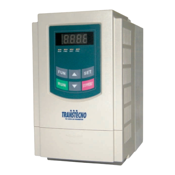
Page 4: Nameplate
Fig 1-1 Nameplate Appearance The external structure of TT100 series inverter is classified into plastic and metal housings. And wall hanging type is adopted. Good poly-carbon materials are adopted through die-stamping for plastic housing with nice form, good strength and toughness. -
Page 5: Technical Specifications
TT100 1.5 Technical Specifications Table1-1 Technical Specifications for TT100 Series Inverters Items Contents Rated Voltage Range 3-phase 400V±15%; single-phase 230V±15% Input Rated Frequency 50/60Hz Rated Voltage Range 3-phase 0~400V;3-phase 0~230V Output Frequency Range 0.50~650.0Hz 2000~10000Hz; Fixed carrier-wave and random carrier-wave Carrier Frequency can be selected by F159. -
Page 6: Designed Standards For Implementation
TT100 Protection IP20 level Applicable 0.2~15KW Motor 1.6 Designed Standards for Implementation IEC/EN 61800-5-1: 2003 Adjustable speed electrical power drive systems safety requirements. IEC/EN 61800-3: 2004 Adjustable speed electrical power drive systems-Part 3: EMC product standard including specific test methods. 1.7 Safe instructions ... -
Page 7: Precautions
Signal line should not be too long to avoid any increase with common mode interference. It shall comply with the requirements for surrounding environment as stipulated in Table 1-1 “Technical Specifications for TT100 Series Inverter”. 1.8.2 Special Warning!! Never touch high-voltage terminals inside the inverter to avoid any electric shock. - Page 8 TT100 All safety covers should be well fixed before inverter is power connected, to avoid any electric shock. Only professional personnel are allowed for any maintenance, checking or replacement of parts. No live-line work is allowed. 1.9 Maintenance 1.9.1 Periodic Checking ...
-
Page 9: Keypad Panel
II. Keypad panel Keypad panel and monitor screen are both fixed on keypad controller. Two kinds of controllers (with and without potentiometer) are available for TT100 series inverters. Refer to note for Fig2-1. Panel Illustration The panel covers three sections: data display section, status indicating section and keypad operating section, as shown in Fig. -
Page 10: Panel Structure
TT100 2.2 Panel structure structure diagram 2. Structure size (Unit: mm) Code Opening size 73*49 121*71 2.3 Panel Operating All keys on the panel are available for user. Refer to Table 2-1 for their functions. Table 2-1 Uses of Keys Keys Names Remarks... -
Page 11: Parameters Setting
TT100 Parameters Setting This inverter has numerous function parameters, which the user can modify to effect different modes of operation control. User needs to realize that if user sets password valid (F107=1), user‟s password must be entered first if parameters are to be set after power off or protection is effected, i.e., to call F100 as per the mode in Table 2-2 and enter the correct code. -
Page 12: Panel Display
TT100 function code will circularly keep increasing or decreasing by degrees within the group; if press the “stop/reset” key again, function code will change circularly between two code groups when operating the “▲” or “▼” key. e.g. when function code shows F111 and DGT indicatoris on, press “▲”/ “▼” key, function code will keep increasing or decreasing by degrees within F100~F160;... -
Page 13: Installation & Connection
TT100 III. Installation & Connection Installation Inverter should be installed vertically, as shown in Fig 3-1. Sufficient ventilation space should be ensured in its surrounding. Clearance dimensions (recommended) are available from Table 3-1 for installing the inverter. Table 3-1 Clearance Dimensions Inverter Model Clearance Dimensions Hanging (≤... -
Page 14: Function Of Control Terminals
TT100 (The figure is only sketch, terminals order of practical products may be different from the above-mentioned figure.) Introduction of terminals of power loop Terminal Terminals Terminal Function Description Marking Power Input R/L1, S/L2, Input terminals of three-phase 400V AC voltage (R/L1 and S/L2 Terminal T/L3 terminals for single-phase) - Page 15 TT100 When the token function is valid, the value Multifunctional between this terminal and CM is 0V; when the output terminal 1 inverter is stopped, the value is 24V. The functions of output When the token function is valid, the value Multifunctional terminals shall be defined Note...
- Page 16 TT100 realize free stop. When this terminal is in the valid state, Running terminal inverter will run by the acceleration time. Make this terminal valid during running can Stop terminal realize stop by the deceleration time. Grounding of Common control power The grounding of 24V power supply and other control signals.
- Page 17 TT100 If digital input control terminals are connected by drain electrode, please turn the toggle switch to the end of “PNP”. Wiring for control terminals as follows: 3. Wiring for positive drain electrode (PNP mode) 4. Wiring for active drain electrode (PNP mode) Wiring by source electrode is a mode most in use at present.
-
Page 18: Wiring Recommended
16<S 35<S 3.6 Overall Connection and “Three- Line” Connection * Refer to next figure for overall connection sketch for TT100 series inverters. Wiring mode is available for various terminals whereas not every terminal needs connection when applied. ·16·... -
Page 19: Operation And Simple Running
TT100 Note: 1. Please only connect power terminals L1/R and L2/S with power grid for single-phase inverters. 2. Remote-control panels and 485 communication port should be connected with 4 core telephone wire. They must not be used at the same time. 3. -
Page 20: Control Mode
TT100 This chapter defines and interprets the terms and nouns describing the control, running and status of the inverter. Please read it carefully. It will be helpful to your correct operation. 4.1 Control mode Control mode of TT100 inverter is V/F control. 4.2 Mode of torque compensation Linear compensation (F137=0);... - Page 21 TT100 before operation. 4.6.1 Method of operating the keypad panel (1) Operation process of setting the parameters through keypad panel A three-level menu structure is adopted for setting the parameters through keypad panel of inverter, which enables convenient and quick searching and changing of function code parameters. Three-level menu: Function code group (first-level menu) →...
- Page 22 TT100 2. In order to ensure dynamic control performance of the inverter, set F800=1, i.e. select stator resistance parameter measurement. Press the “Run” key on the keypad, and the inverter will display “TEST”, after few seconds, self-checking is completed, motor stator resistance parameters will be stored in function code F806, and F800 will turn to 0 automatically.
- Page 23 TT100 After successful test run under no load, connect the load of drive system properly. Start the inverter with the keypad or control terminal, and increase the load gradually. When the load Checking under with is increased to 50% and 100%, keep the inverter run for a period respectively, to check if the system is running normally.
- Page 24 TT100 ⑥ Enter F800 parameter and set it to 1 to allow measuring the parameter of the motor ⑦ Press the “Run” key, to measure the parameters of the motor. After completion of the measurement, and relevant parameters will be stored in F806. For the details of measurement of motor parameters, please refer to “Operation process of measuring the motor parameters”...
- Page 25 TT100 (7) During running, switch off the switch OP3, then close the switch OP4, the running direction of the motor will be changed (Note: The user should set the dead time of forward and reverse running F120 on the basis of the load. If it was too short, OC protection of the inverter may occur.) (8) Switch off the switches OP3 and OP4, the motor will decelerate until it stops running;...
-
Page 26: Function Parameters
TT100 (2) Press the “Fun” key, to enter the programming menu. (3) Study the parameters of the motor: the operation process is the same as that of example 1. (4) Set functional parameters of the inverter: ① Enter F203 parameter, and set it to 1; select the mode of frequency setting of analog AI1, 0~10V voltage terminal;... - Page 27 TT100 ·When F107=1 with valid password, the user must enter correct user‟s password after power on or fault reset if you intend to change parameters. Otherwise, parameter setting will not be possible, and a prompt “Err1” will be displayed. Relating function code: F107 Password valid or not F108 Setting user‟s password...
- Page 28 TT100 lower than min frequency, then inverter will run at min frequency until inverter stops or given frequency is higher than min frequency. Max/Min frequency should be set according to the nameplate parameters and running situations of motor. The motor is forbidden running at low frequency for a long time, or else motor will be damaged because of overheat. Mfr‟s value: 50.00Hz F113 Target Frequency (Hz) Setting range: F112~F111...
- Page 29 TT100 ·In the mode of combined speed control, if running frequency is minus and F123=0, inverter willrun at 0Hz; if F123=1, inverter will run reverse at this frequency. (This function is controlled by F122.) Mfr‟s value: 5.00Hz F124 Jogging Frequency (Hz) Setting range: F112~F111 Mfr‟s value: For 0.2~3.7KW, 5.0S F125 Jogging Acceleration Time (S)
- Page 30 TT100 0-Current output frequency/function-code 1-Output rotary speed 2-Output current 4-Output voltage Mfr‟s value: F131 Running Display Items 8-PN voltage 0+1+2+4+8=15 16-PID feedback value 32-Temperature 64-Count values 128-Linear speed · Single-phase 0.2~0.75KW inverters have no the function of temperature display. ·Selection of one value from 1, 2, 4, 8, 16, 32, 64 and 128 shows that only one specific display item is selected.
- Page 31 TT100 =60×50/ (2×1.00) =1500rpm Endmost linear speed: rotary speed × perimeter=1500×0.314=471(meters/second) Mfr‟s value: 0 F136 Slip compensation Setting range: 0~10% · Under V/F controlling, rotary speed of motor rotor will decrease as load increases. Be assured that rotor rotate speed is near to synchronization rotary speed while motor with rated load, slip compensation should be adopted according to the setting value of frequency compensation.
- Page 32 TT100 Mfr‟s value: 10.00 F144 User-defined frequency point F3 Setting range: F142~F146 Mfr‟s value: 24 F145 User-defined voltage point V3 Setting range: 0~100% Mfr‟s value: 20.00 F146 User-defined frequency point F4 Setting range: F144~F148 Mfr‟s value: 45 F147 User-defined voltage point V4 Setting range: 0~100%...
- Page 33 TT100 Mfr‟s value: Setting range: 0.2~7.5KW:2~10K F153 Carrier frequency setting 11~15KW: 2~10K Carrier-wave frequency of inverter is adjusted by setting this code function. Adjusting carrier-wave may reduce motor noise, avoid point of resonance of mechanical system, decrease leakage current of wire to earth and the interference of inverter.
- Page 34 TT100 carrier-wave set by F153 is selected, nosie will be reduced, but output torque will decrease. Please set the value according to the situation. Setting range: Mfr‟s value: 0 0: Not reverting to manufacturer values; F160 Reverting to manufacturer values 1: Reverting to manufacturer values ·When there is disorder with inverter‟s parameters and manufacturer values need to be restored, set F160=1.
-
Page 35: Operation Control
TT100 5.2 Operation Control Setting range: F200 0: Keypad command; Mfr‟s value: 0 Source of start 1: Terminal command; 2: Keypad+Terminal; command 3: MODBUS; 4: Keypad+Terminal+MODBUS Setting range: F201 0: Keypad command; Mfr‟s value: 0 Source of stop 1: Terminal command; 2: Keypad+Terminal; command 3: MODBUS;... - Page 36 TT100 Its initial value is the value of F113. The frequency can be adjusted through the key “up” or “down”, or through the “up”, “down” terminals. “Memory of digital given” means after inverter stops, the target frequency is the running frequency before stop.
- Page 37 TT100 frequency is set by F156, the initial value of accessorial frequency and the polarity of accessorial frequency can be checked by F157 and F158. · When the accessorial frequency is given by analog input (AI1, AI2), the setting range for the accessorial frequency is set by F205 and F206.
- Page 38 TT100 analog given still exists, inverter will run by analog given. 2. Frequency given mode can be switched over by selecting F207. For example: switching PID adjusting and normal speed control, switching stage speed and analog given, switching PID adjusting and analog given, and so on.
- Page 39 TT100 Running command Stop Forward running Reverse running Stop 2. Two-line operation mode 2: when this mode is used, FWD is enable terminal, the direction is controlled by REV terminal. For example: “FWD” terminal-----“open”: stop, “closed”: running; “REV” terminal-----“open”: forward running, “closed”: reverse running; “CM”...
- Page 40 TT100 5. Start/stop controlled by direction pulse: “FWD” terminal—(impulse signal: forward/stop) “REV” terminal—(impulse signal: reverse/stop) “CM” terminal—common port Note: when pulse of SB1 triggers, inverter will run forward. When the pulse triggers again, inverter will stop running. When pulse of SB2 triggers, inverter will run reverse. When the pulse triggers again, inverter will stop running.
- Page 41 TT100 stopped status, the inverter will only reset automatically. When F214=0, after fault occurs, inverter will display fault code, it must be reset manually. Mfr‟s value: 60.0 F215 Selfstarting delay time Setting range: 0.1~3000.0 F215 is the selftstarting delay time for F213 and F214. The range is from 0.1s to 3000.0s. Mfr‟s value: 0 F216 Times of selfstarting in case of repeated faults Setting range: 0~5 Mfr‟s value: 3.0...
-
Page 42: Multifunctional Input And Output Terminals
TT100 5.3. Multifunctional Input and Output Terminals 5.3.1 Digital multifunctional output terminals Mfr‟s value: 1 F300 Relay token output Setting range: 0~18 Mfr‟s value: 14 F301 DO1 token output Refer to table 5-2 for detailed instructions. Mfr‟s value: 5 F302 DO2 token output TT100 inverter has one multifunctional relay output terminal. - Page 43 TT100 reserved reserved Setting range: 0: level output : pulse output Mfr‟s value: 0 F303 DO output types selection · When level output is selected, all terminal functions in table 5-2 can be defined by F301. · When pulse output is selected, DO1 can be defined as high-speed pulse output terminal. The max pulse frequency is 50KHz.
- Page 44 TT100 programmed with “reaching the set count values” function when a certain number of pulses are input from OP1, until count value reaches the “set times”. As shown in Fig 5-6: if F313=1、F314=8,F315=5,F300=9, relay will output an instruction signal pulse, relay will output an instruction signal until reaching “set count times 8”. when OP1 inputs the 5 OP1 Input: DO1:...
- Page 45 TT100 Even if signal is input, inverter will not work. This function can be No function set by undefined terminal to prevent mistake action. When running command is given by terminal or terminals Running terminal combination and this terminal is valid, inverter will run. This terminal has the same function with “run”...
-
Page 46: Analog Input And Output
F324=1 and F325=1, negative logic and high level is valid. 5.4 Analog Input and Output TT100 series inverters have 2 analog input channels and 2 analog output channels. AI3 input channel is inside input channel for potentiometer on the keypad panel. - Page 47 TT100 Setting range: Mfr‟s value: 2.00 F403 Corresponding setting for upper limit of AI1 input Max (1.00,F401) ~2.00 Mfr‟s value: 1.0 F404 AI1 channel proportional gain K1 Setting range: 0.0~10.0 Mfr‟s value: 0.10 F405 AI1 filtering time constant Setting range: 0.1~10.00 ·In the mode of analog speed control, sometimes it requires adjusting coincidence relation among upper limit and lower limit of input analog, analog changes and output frequency, to achieve a satisfactory speed control effect.
- Page 48 TT100 Corresponding setting (Frequency) 100.0% (20mA) (0mA) -100.0% Fig 5-6 correspondence of analog input to setting The unit of corresponding setting for upper / lower limit of input is in percentage (%). If the value is greater than 1.00, it is positive; if the value is less than 1.00, it is negative.
- Page 49 F420=N, then 2.5±N should correspond to 0Hz. If the voltage is in this range, inverter will output 0Hz. 0HZ voltage dead zone will be valid when corresponding setting for lower limit of input is less than 1.00. TT100 series inverters have two analog output channels. F437 Analog filter width Setting range: 1~100...
- Page 50 TT100 F429. When folding line mode is selected, three points A1(B1) 、A2(B2)、A3(B3) are inserted into the straight line, each of which can set the according frequency to input voltage. Please refer to the following figure: According setting (frequency) 100% F400 A3 F402 Fig 5-9 Folding analog with setting value F400 and F402 are lower/upper limit of analog AI1 input.
- Page 51 TT100 1: Output current; Mfr‟s value: 1 F432 AO2 analog output signal selecting 2: Output voltage; 3~5: Reserved · Token contents output by analog channel are selected by F431 and F432. Token contents include running frequency, output current and output voltage. ·...
- Page 52 TT100 Input pulse 0-10K can correspond to output frequency -50Hz~50Hz (5K corresponds to 0Hz) by setting the function of corresponding setting for max/min input pulse frequency. The function code F446 sets the input pulse range corresponding to 0Hz. For example, when F446=0.5, the pulse range from (5K-0.5K=4.5K) to (5K+0.5K=5.5K) corresponds to 0Hz.
-
Page 53: Multi-Stage Speed Control
The function of multi-stage speed control is equivalent to a built-in PLC in the inverter. This function can set running time, running direction and running frequency. TT100 series inverter can realize 15-stage speed auto circulating and 8-stage speed auto circulating. Setting range: 0: 3-stage speed;... - Page 54 TT100 Setting range: 0~9999 F502 Selection of Times of Auto-circulation Mfr‟s value: 0 (when the value is set to 0, the inverter Speed Control will carry out infinite circulating) Setting range: F503 Status After Auto-circulation Mfr‟s value: 0 0: Stop 1: Keep running at last-stage speed Running Finished.
-
Page 55: Auxiliary Functions
TT100 Mfr‟s value: 25.00Hz F516 Frequency setting for stage 13 speed Mfr‟s value: 30.00Hz F517 Frequency setting for stage 14 speed Mfr‟s value: 35.00Hz F518 Frequency setting for stage 15 speed Mfr‟s value: F519~F533 Acceleration time setting for the Setting range: speeds from Stage 1 to Stage 15 0.1~3000S 0.2-3.7KW: 5.0S... - Page 56 TT100 selected, after output frequency declines to initial frequency for DC braking, the rotating motor is stop by DC braking. During the process of braking during stopping, if “start” signal is given, DC braking is finished and inverter will start. If “stop”...
-
Page 57: Malfunction And Protection
TT100 higher than the setting value of this function, energy consumption braking starts, braking unit starts working. After DC bus voltage is lower than the setting value, braking unit stops working. Discharging percentage of braking unit is set by F612, the range is 0~100%. 5.8. - Page 58 TT100 3: over voltage (OE) 4: input out-phase (PF1) 5: inverter overload (OL1) 6: under voltage (LU) 7: overheat (OH) F710 Record of Malfunction Type for Last but Two 8: motor overload (OL2) 11: external malfunction (ESP) 13. studying parameters without motor (Err2) 16: software over current (OC1) 17: output out-phase (PF0)
-
Page 59: Parameters Of The Motor
TT100 current. In running status, F738 can not be changed. When over current occurred, OC1 is displayed. 5.9 Parameters of the Motor Setting range: F800 Motor‟s parameters selection Mfr‟s value: 0 0: no parameter measurement; 1: Stator resistance parameter measurement; F801 Rated power Setting range: 0.2~1000KW F802 Rated voltage... -
Page 60: Pid Parameters
TT100 Please set F901 to 3 to select remote controlling keypad, the keypad of inverter will automatically close for saving energy. If the keypad of inverter and remote controlling keypad need work at the same time, please connect OP5 terminal to CM terminal. When inverter works steadily, please disconnect OP5 with CM in case malfunction. F904=9600 is recommended for baud rate, which makes run steady. -
Page 61: Appendix 1 Trouble Shooting
TT100 Appendix 1 Trouble Shooting When malfunction occurs to inverter, don‟t run by resetting immediately. Check any causes and get it removed if there is any. Take counter measures by referring to this manual in case of any malfunctions on inverter. Should it still be unsolved, contact the manufacturer. - Page 62 Products & Structures TT100 series inverter has its power range between 0.2~15 KW. Refer to Tables 2-1 and 2-2 for main data. There may be two (or more than two) kinds of structures for certain products. Please make a clear indication when placing your order.
- Page 63 TT100 Table 2-2 TT100 Types of Product Structure Structure External Dimension Mounting Mounting Remarks note1 Code Size Bolt [A×B(B1)×H] (W×L) 80×135(142)×138 70×128 106×150(157)×180 94×170 106×170(177)×180 94×170 正在研发 138×152(159)×235 126×225 156×170(177)×265 146×255 205×196(202)×340 194×330 Note 1: the unit is mm. Plastic Profile ·61·...
-
Page 64: Appendix 3 Selection Of Braking Resistance
TT100 Appendix 3 Selection of Braking Resistance Applicable Motor Inverter Models Applicable Braking Resistance Power(KW) TT100-0002S2 TT100-0004S2 150W/60Ω TT100-0007S2 0.75 TT100-0015S2 TT100-0022S2 80W/200Ω TT100-0007T3 0.75 80W/150Ω TT100-0015T3 TT100-0022T3 150W/150Ω TT100-0037T3 TT100-0040T3 250W/120Ω TT100-0055T3 500W/120Ω TT100-0075T3 1KW/90Ω TT100-0110T3C 1.5KW/80Ω TT100-0150T3C ·62·... -
Page 65: Appendix 4 Communication Manual
TT100 Appendix 4 Communication Manual (Version 1.8) I. General Modbus is a serial and asynchronous communication protocol. Modbus protocol is a general language applied to PLC and other controlling units. This protocol has defined an information structure which can be identified and used by a controlling unit regardless of whatever network they are transmitted. -
Page 66: Error Check
TT100 Byte Function Start Bit (Low Level) Data Bit Parity Check Bit (None for this bit in case of no checking. Otherwise 1 bit) Stop Bit (1 bit in case of checking, otherwise 2 bits) 2) RTU mode Byte Function Start Bit (Low Level) Data Bit Parity Check Bit (None for this bit in case of no checking. - Page 67 TT100 the LSB. 4. (If the LSB was 0): Repeat Step 3 (another shift). (If the LSB was 1): Exclusive OR the CRC register with the polynomial value A001 hex (1010 0000 0000 0001). 5. Repeat Steps 3 and 4 until 8 shifts have been performed. When this is done, a complete 8–bit byte will have been processed.
- Page 68 TT100 2) Use different parameters as parameter address (The above address and parameters descriptions are in hexadecimal format, for example, the decimal digit 4096 is represented by hexadecimal 1000). 1. Running status parameters Parameters Address Parameter Description(read only) 1000 Output frequency 1001 Output voltage 1002...
- Page 69 TT100 Illegal Response When Reading Parameters Command Description Function Data Slave parameters response The highest-oder byte changes into 1. Command meaning: 0001: Illegal function code 0002: Illegal address 0003: Illegal data note 2 0004: Slave faultnote Note 2: Illegal response 0004 appears below two cases: 1.
- Page 70 TT100 0: Digital setting memory; 1: External analog AI1; 2: External analog AI2; 3: Pulse input given; 4: Stage speed control; F203 Main frequency source X 5: No memory by digital setting; 6:Keypad potentiometer; 7~8: Reserved; 9: PID adjusting 10: MODBUS F900 Inverter Address...
- Page 71 TT100 with PC/PLC. Should two or more than two inverters upload data at the same time, then bus competition will occur, which will not only lead to communication failure, but higher current to certain elements as well. 3. Grounding and Terminal ...
- Page 72 TT100 The max value of function code is 1. Slave fault Eg 2:Read output frequency, output voltage, output current and current rotate speed from N0.2 inverter. Host Query First Register First Register Register Register Address Function Address Hi Address Lo count Hi count L0 Communication Parameters Address 1000H...
- Page 73 TT100 Communication Parameter Address F10DH Numbers of Read Registers ·71·...
- Page 74 TT100 Slave Normal Response: The first The first The second The second Byte Address Function parameters parameters parameters parameters count status Hi status Lo status Hi status Lo The actual value is 10.00. The actual value is 12.00. Slave Abnormal Response: Address Function Code Abnormal Code...
-
Page 75: Appendix 5 Zoom Table Of Function Code
TT100 Appendix 5 Zoom Table of Function Code Function Function Function Mfr’s Value Setting Range Change Code Definition Section User‟s Password √ F100 0~9999 Inverter‟s Rated Current (A) F102 1.0~800.0 Subject to inverter model F103 Inverter Power (KW) 0.20~650.0 Subject to inverter model F104 Inverter Power Code 100~400... - Page 76 TT100 √ F127 Skip Frequency A 0.00~650.0Hz 0.00Hz √ F128 ±2.50Hz 0.00 Skip Width A √ F129 0.00~650.0Hz 0.00Hz Skip Frequency B √ F130 ±2.50Hz 0.00 Skip Width B 0-Present output frequency / function code 1-Current output rotary speed 2-Output current 4-Output voltage √...
- Page 77 TT100 ╳ F144 User-defined frequency point 3 F142~F146 10.00 ╳ F145 User-defined voltage point 3 0~100% ╳ F146 User-defined frequency point 4 F144~F148 20.00 ╳ F147 User-defined voltage point 4 0~100% ╳ F148 User-defined frequency point 5 F146~F150 30.00 ╳ F149 User-defined voltage point 5 0~100%...
- Page 78 TT100 0: Digital setting memory; 1: External analog AI1; 2: External analog AI2; 3: Pulse input given; 4: Stage speed control; ╳ F203 Main frequency source X 5: No memory by digital setting; 6:Keypad potentiometer; 7-8: Reserved; 9: PID adjusting; 10: MODBUS 0: Digital setting memory;...
- Page 79 TT100 Mfr’s Function Function Function Setting Range Change Code Definition Value Section 0: no function; 1: inverter fault protection; √ F300 Relay token output 2: over latent frequency 1; 3: over latent frequency 2; 4: free stop; 5: inverter running status 1; 6: DC braking;...
- Page 80 TT100 0: no function; OP1 terminal function √ F316 1: running terminal; setting 2: stop terminal; 3: multi-stage speed terminal 1; OP2 terminal function √ F317 4: multi-stage speed terminal 2; setting 5: multi-stage speed terminal 3; 6: multi-stage speed terminal 4; OP3 terminal function √...
- Page 81 TT100 Upper limit of AI2 √ F408 F406~10.00V 10.00V channel input Corresponding setting for √ F409 Max(1.00,F407)~2.00 2.00 upper limit of AI2 input AI2 channel √ F410 0.0~10.0 proportional gain K2 AI2 filtering time constant √ F411 0.1~50.0 Lower limit of AI3 √...
- Page 82 TT100 F438~F439 Reserved AI1channel input mode 0: straight line mode ╳ F460 1: folding line mode AI2 channel input mode 0: straight line mode ╳ F461 1: folding line mode AI1 inseration point A1 F400~F464 2.00V ╳ F462 voltage value AI1 inseration point A1 F401~F465 1.40...
- Page 83 TT100 0: Running frequency 1: Output current √ F453 Output pulse signal 2: Output voltage 3~5: reserved Function Function Function Mfr’s Value Setting Range Change Code Definition Section 0: 3-stage speed; 1: 15-stage speed; ╳ Stage speed type F500 2: Max 8-stage speed auto circulating Selection of Stage Speed √...
- Page 84 TT100 Acceleration time setting for 0.2~3.7KW:5.0S; √ F519~F533 the speeds from Stage 1 to 0.1~3000S 5.5~30KW:30.0S; stage 15 Above 37KW: 60.0S Deceleration time setting for 0.2~3.7KW:5.0S; √ F534~F548 the speeds from Stage 1 to 0.1~3000S 5.5~30KW:30.0S; stage 15 Above 37KW: 60.0S Running directions of 0: forward running;...
- Page 85 TT100 Function Function Function Mfr’s Value Setting Range Change Code Definition Section Selection of terminal 0: free stop immediately; √ F700 free stop mode 1: delayed free stop Delay time for free stop √ F701 and programmable 0.0~60.0s terminal action 0:controlled by temperature ╳...
- Page 86 TT100 Record of overvoltage △ F721 protection fault times Record of overheat △ F722 protection fault times Record of overload △ F723 protection fault times ╳ F724 Input out-phase 0: invalid; 1: valid ╳ F725 Undervoltage 0: invalid; 1: valid ╳...
- Page 87 TT100 Mfr’s Function Function Function Setting Range Change Code Definition Value Section Setting range: Motor‟s parameters ╳ 0: no parameter measurement; F800 selection 1:Stator resistance parameter measurement; ╳ F801 Rated power 0.2~1000KW ╳ F802 Rated voltage 1~440V ╳ F803 Rated current 0.1~6500A ╳...
- Page 88 TT100 √ Feedback limit value FA12 0~100 (%) √ Dormancy delay time FA13 0~300.0 (S) 60.0S √ Wake delay time 60.0S FA14 0~300.0 (S) FA15~FA30 Reserved Note: × indicating that function code can only be modified in stop state. √ indicating that function code can be modified both in stop and run state. △...
Need help?
Do you have a question about the TT100 series and is the answer not in the manual?
Questions and answers