Table of Contents
Advertisement
Advertisement
Table of Contents

Related Manuals for TELEREADER CWR-610E

Summary of Contents for TELEREADER CWR-610E
- Page 1 Code Master Model CWR-610E OPERATING INSTRUCTIONS...
-
Page 2: Table Of Contents
CONTENTS RATING ...................... 3 DESCRIPTION OF PANELS ................5 METHOD OF USE Preparation ..................7 Reception of CW ................7 Code interpretable range and word space ........... 7 Reception of RTTY ................8 Reception of commercial station ............9 CONNECTABLE PRINTERS ................9 CONNECTION OF EXTERNAL TERMINALS OR CW HAND KEY ...... -
Page 3: Rating
RATING Reception codes CW - Morse Alphabet, numerals, symbols, special codes. RTTY Baudot code 5-unit Baudot code (CCITT No. 2): 1 start bit, 5 code bits, 1.5 stop bits. Total 7.5 bits. ASCII code 7-unit ASCII code (ISO/CCITT No. 5): 1 start bit, 7 code bits, 1 parity bit, 2 stop bits. - Page 4 CW random generator (Code Practice = CP generator) Produced codes Alphabet and numerals Speed 2 wpm to 30 wpm Power source DC 12 V, 700 mA (usable in DC 10 V to 13.8 V) Overall dimensions 160 mm wide × 205 mm deep × 50 mm high. Weight 1.1 kg Accessories...
-
Page 5: Description Of Panels
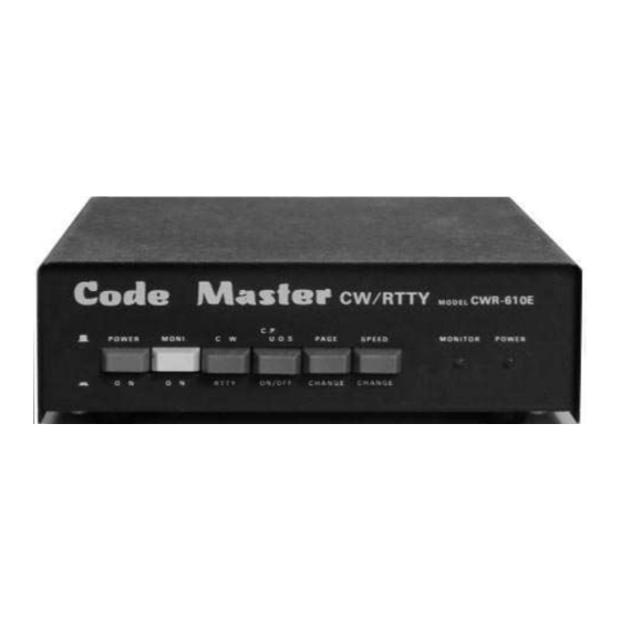
DESCRIPTION OF PANELS FRONT PANEL POWER Power switch MONI Monitor sound ON/OFF switch, and also used as CP start prohibition switch. Only when the switch is in ON position, monitor sound is oscillated. When the switch is turned OFF, in CP mode, only the random number display characters are updated and operation is not started;... - Page 6 REAR PANEL RF OUT For connection with antenna input terminal of home TV. When changed to VIDEO OUT inside, this terminal is used to connect with monitor VR-4 This is used to adjust the clock frequency for baud rate to 4,800 Hz in RTTY. It has been correctly adjusted before shipping and should not be turned except when re- adjusting.
-
Page 7: Method Of Use
METHOD OF USE Preparation When connecting with a transceiver, arrange so that the case side of this unit and that of the transceiver may be at the same potential. Connect the AF. IN terminal on the rear panel with the external speaker terminal of the transceiver. Connect from the RF. -
Page 8: Reception Of Rtty
The correspondence between the display characters and the telegraph codes is shown in the attached sheet. Reception of RTTY Since the unit incorporates a PLL system one side demodulator, it can receive commercial, mete- orological and amateur communication with a certain signal intensity. When an optional terminal unit is connected by using external input terminal (TTL. -
Page 9: Reception Of Commercial Station
Reception of commercial station Since the transmission speed of a commercial station is usually 50 bauds, adjust the speed accord- ing to the section of the adjustment. The shift width is normally more than 170 Hz, and the MONITOR LED lights up from the low beat pitch side as shown below: Goes out Flickers... -
Page 10: Connection Of External Terminals Or Cw Hand Key
CONNECTION OF EXTERNAL TERMINALS OR CW HAND KEY 1. Feed the output of external demodulator into TTL. IN terminal at RS-232C level by using ear- phone plug. When the Output of external demodulator is at TTL level, cut the [Cut land REV]. 2. - Page 11 Adjust of RF OUT frequency This set is adjusted according to the CCIR European standard VHF ch 4 (62.25 MHz). If fine ad- justment is necessary, turn the core of RF coil. Frequency increased. Frequency decreased. Coil In the Australian specifications, the set is adjusted to VHF ch 1 (57.25 MHz) CHANGEOVER Changing method when using video monitor TV instead of home TV Changing from RF OUT to VIDEO OUT...
- Page 12 To control normal/reverse selection from outside, provide a switch between clock terminals 1 and 3. When the [cut land REV] is cut, the operation is changed as follows: The internal demodulator becomes a space demodulator. The TTL. IN is changed to mark H, space L input.
-
Page 13: Display Screen And Operation Status Display
DESCRIPTION OF DISPLAY SCREEN Two screen, containing 36 characters by 17 lines each, are changed over and appear as shown be- low: The following messages appear in the operation status display area: Mode Status display 1 Status display2 <Morse Code> <Morse Code>... -
Page 14: Cp (Cw Random Generator)
Baudot and ASCII are automatically exchanged when the baud rate is changed over. CP (CW random generator) Change to CP mode: 1. Push down MONI switch. 2. Turn RTTY/CW selector to CW side. The CW mode is selected. 3. Turn on power switch. 4. - Page 15 Page 2 ..In this screen, after sending of codes, the corresponding characters are dis- played. The wpm display changes according to the selection from 2 to 30 CP-ON display is changed to OFF and to ON again by selection of CP UOS switch. Even if CP-ON, when MONI switch is turned off, only the display appears and operation is not started.
-
Page 16: Layout Of Adjusting Volumes And Switching Spots
LAYOUT OF ADJUSTING VOLUMES AND SWITCHING SPOTS - 16 -... -
Page 17: Correspondence Chart Of Display Characters And Codes (Cw)
CORRESPONDENCE CHART OF DISPLAY CHARACTERS AND CODES (CW) Display Code Display Code ·– ·–·–·– (period) –··· ––··–– (comma) –·–· –––··· (colon) –·· ··––·· · ·––––· (apostrophe) ··–· –····– (dash) ––· –·––· ···· –·––·– ·· –··–· ·––– –···– (BT) –·– ·–·–· (AR) ·–··...
Need help?
Do you have a question about the CWR-610E and is the answer not in the manual?
Questions and answers