
Summary of Contents for LUDLUM 2360
- Page 1 LUDLUM MODEL 2360 SCALER/RATEMETER DATA LOGGER July 2016 Serial Number 133669 and Succeeding Serial Numbers...
- Page 2 LUDLUM MODEL 2360 SCALER/RATEMETER DATA LOGGER July 2016 Serial Number 133669 and Succeeding Serial Numbers...
- Page 3 RETURN OF GOODS TO MANUFACTURER If equipment needs to be returned to Ludlum Measurements, Inc. for repair or calibration, please send to the address below. All shipments should include documentation containing return shipping address, customer name, telephone number, description of service requested, and all other necessary information.
-
Page 5: Table Of Contents
Environmental Conditions for Normal Use Cleaning Instructions and Precautions Warning Markings and Symbols Calibration and Maintenance Calibration Establishing an Operating Point Meter Calibration Detector Overload Calibration Maintenance Recalibration Batteries RS-232 Interface Communicating With the Model 2360 Commands Read Commands Ludlum Measurements, Inc. July 2016... - Page 6 Main Screen Auto Dump Data (Setup) Model 2360 Interface Software Sample Printouts 7-10 Installation of the 2360 Interface Software 7-12 Removal of the Model 2360 Interface Software 7-13 Connecting to a Computer 7-13 Software License Agreement 7-14 Technical Theory of Operation...
-
Page 7: Introduction
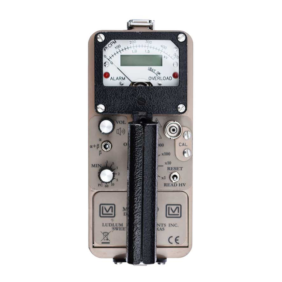
The Model 2360 has a long arc length (6.0 cm {2.4 in.}) meter face that normally reads from 0 to 500 cpm. The main rotary switch allows for multiplication ranges of ×1, ×10, ×100, and ×1000. - Page 8 The Model 2360 communicates through an RS-232 port located on the instrument can. The computer interface software is supplied on CD and...
-
Page 9: Getting Started
The Model 2360 serial number is located on the front panel below the battery compartment. Most Ludlum Measurements, Inc. detectors have a label on the base or body of the detector for model and serial number identification. -
Page 10: Connecting A Detector To The Instrument
Internal Switches Release the can latches and remove the cover from the 2360, taking care not to damage the speaker wires. Using a ball-point pen, set the switches for the... -
Page 11: Operating The Instrument
Proceed with use. Principle of Operation The Model 2360 is to be used in combination with an alpha/beta scintillation or proportional detector. The pulse height differential between the alpha and beta pulses from the scintillation or proportional detector is discriminated by the Model 2360. - Page 12 Model 2360 Technical Manual Section 2 the meter dial by selecting the position. The high-voltage scale READ HV ranges from 0 to 2 kV. The (overload) lamp, located in the lower, right corner of the meter dial, indicates that the detector is saturated either by a puncture in the detector face or an exposure to a radiation field above the counting capability of the instrument.
-
Page 13: Specifications
Model 2360 Technical Manual Section 3 Section Specifications : proportional and dual phosphor scintillation Compatible Detectors detectors; common Models: 43-1-1, 43-2-2, 43-20, 43-68, 43-89 and 43- : capable of logging up to 550 individual data points into Data Logger non-volatile memory with the following identifiers for each point:... - Page 14 Model 2360 Technical Manual Section 3 : six separate alarm points, set through the RS-232 port, Alarm points activating the alarm audio tone and lighting the LED. The six ALARM alarm points can be set from 0 to 99999. Ratemeter alarms are non- latching, while scaler alarms are not.
-
Page 15: Description Of Controls And Functions
Model 2360 Technical Manual Section 4 Section Description of Controls and Functions Operator Controls OFF/BAT/X1000/X100/X10/X1 Switch (or Range Selector Switch): a six- position rotary switch to select the analog meter range multipliers and check the battery status. When switched to the ˝... - Page 16 Model 2360 Technical Manual Section 4 : A three-position toggle switch used to select the sum of α/α+β/β Switch alpha and beta count channels (α ), alpha count only (α), or beta count Β only ( ), for display. This switch affects both the analog meter and digital Β...
-
Page 17: Internal Controls
Model 2360 Technical Manual Section 4 Internal Controls Remove the instrument cover (can) to access the following dipswitches on SW1. : A one-pole DIP switch (#1) used to select recycle scaler RECYCLE mode. When placed in the position, the instrument will start a count cycle. - Page 18 Model 2360 Technical Manual Section 4 SWITCH DIVIDE BY RATIO Beta audio Subtract Mode : A two-pole DIP switch (#5 & #6) used to select logging LOG SAMPLE mode. When both switches are , the instrument will not log samples but will output the ratemeter readings to the RS-232 port every two seconds in ASCII format.
- Page 19 Model 2360 Technical Manual Section 4 : a multi-turn potentiometer used to set the maximum limit to 2000 Vdc : a multi-turn potentiometer used to adjust the high-voltage test reading (0 to 2 kV scale) to correspond with the actual high-voltage output.
-
Page 20: Safety Considerations
This is typical of industrial or construction sites.) Cleaning Instructions and Precautions The Model 2360 Scaler/Ratemeter may be cleaned externally with a damp cloth, using only water as the wetting agent. Do not immerse the instrument in any liquid. Observe the following precautions when cleaning: 1. - Page 21 Verify instrument voltage input rating before connecting to a power converter. If the wrong power converter is used, the instrument and/or power converter could be damaged. The Model 2360 Scaler/Ratemeter is marked with the following symbols: CAUTION (per ISO 3864, No. B.3.1) – designates hazardous live voltage and risk of electric shock.
-
Page 22: Calibration And Maintenance
Connect a Ludlum Model 500 Pulser or equivalent to the Model 2360. Switch the 2360 to the β position. Adjust the beta threshold (BT) for 3.5 mV and the window ( ) for 30 mV. The pulser counts should be detected on the 2360 ratemeter above 3.5 ±... -
Page 23: Meter Calibration
ETER ALIBRATION A Ludlum Model 500 Pulser or equivalent is required. If the pulser does not have high-voltage readout, use a high-impedance voltmeter with at least 1000 megohm input resistance to measure the detector voltage. Ensure that the meter movement has proper mechanical zero. The adjustment is on the front of the meter bezel. -
Page 24: Detector Overload Calibration
Adjust the power supply for 2.2 Vdc and switch the 2360 to the position. Adjust the potentiometer to align the meter needle with the low-... -
Page 25: Maintenance
Maintenance Instrument maintenance consists of keeping the instrument clean and periodically checking the batteries and the calibration. The Model 2360 instrument may be cleaned with a damp cloth (using only water as the wetting agent). Do not immerse instrument in any liquid. Observe the following precautions when cleaning: 1. -
Page 26: Batteries
Check the appropriate regulations to determine required recalibration intervals. Ludlum Measurements offers a full-service repair and calibration department. We not only repair and calibrate our own instruments, but most other manufacturers’ instruments as well. Calibration procedures are available upon request for customers who choose to calibrate their own instruments. -
Page 27: Rs-232 Interface
Section 7 Section RS-232 Interface Communicating with the Model 2360 The Model 2360 has an RS-232 serial port that can be connected to a PC or other RS-232 device. The proper communication settings are (2400,8,N,1): 2400 Baud 8 data bits... -
Page 28: Set Commands
[CR] and [LF]. The format is: 0001[CR][LF] This command reads the calibration date. During power-up, the Model 2360 checks the current date against this date. If the current date is past the calibration date, the message “... - Page 29 012.5[CR][LF] This command reads the current alpha and beta ratemeter reading. When dip-switch 5 and 6 are set to OFF, the Model 2360 sends this message every 2 seconds. The alpha Ratemeter reading is first, followed by the beta ratemeter reading. The output is 15 characters, including a [CR] and [LF].
- Page 30 SCmmddyyyy This command sets the calibration due date. The date is entered in Month- Day-Year (MMDDYYYY) format. During power-up, the Model 2360 checks to see if the current date is past the calibration due date. If it is, then the Model 2360 displays “...
- Page 31 SLTABLE0007[SPACE][CR][LF] This command disables or enables the automatic dumping of the ratemeter when the Model 2360 is set not to log samples (dip-switch 5 and 6 both OFF). Specifying SM0 will disable the ratemeter dumping until the unit is turned off or the command SM1 is issued.
-
Page 32: Model 2360 Interface Software
500 the command is: S1000500[CR][LF] Model 2360 Interface Software The Model 2360 Interface (LMI Part #:1370-039) is Windows-based and has a user-friendly interface, which allows the user to communicate with the Model 2360. The Model 2360 interface features automatically loading default values, and a Auto Dump Mode Display. -
Page 33: Functions
Model 2360, which includes headers and logged data. The user is able to change any information and update the Model 2360, print hard copies, or save data to an ASCII file for later import into word processors, spreadsheets, or other applications. -
Page 34: Main Screen
If there is no logged data, only the parameters will printed. [Comm Setup]—Displays the Select Comm Port screen. Select “Automatic” to allow the software to scan all available serial ports to find the Model 2360. Select “Manual” and choose a specific serial port. Ludlum Measurements, Inc. Page 7-8 July 2016... -
Page 35: Auto Dump Data (Setup)
Section 7 ETUP Note: For auto dumping to work properly, the Model 2360 internal dip switches 5 and 6 must be set to the OFF position. [Two-Second Counts]—The Model 2360 outputs the ratemeter reading every two seconds. This option will capture each two-second reading. -
Page 36: Model 2360 Interface Software Sample Printouts
[Clear]—Clears data from the display box. This only clears the grid and does not affect the samples stored in the memory of the Model 2360. [Auto Scroll Grid]—When checked, the grid automatically scrolls to keep the newest record visible. - Page 37 Model 2360 Technical Manual Section 7 Table 1: Header 1: John Q. Public Header 2: SN: 220859 Header 3: SN: PR200747 Header 4: Site: Bldg 1 Header 5: RM 008, S. Wall Header 6: Comment S=Scaler, R=Ratemeter Sample # Date...
- Page 38 If you do not agree to all the terms of this agreement, do not install the product! Insert the Model 2360 Interface software CD into the computer. The installation routine should start automatically. If it does not, click on the Start button, select “Run”...
-
Page 39: Connecting To A Computer
ONNECTING TO A OMPUTER Using the supplied cable, connect the end with the female connector to the Model 2360 and the other end to a free COM port on your computer. The pin-outs of the cables are as follows: 9-pin cable... - Page 40 Model 2360 Technical Manual Section 7 Ludlum Measurements, Inc. Page 7-14 July 2016...
- Page 41 Model 2360 Technical Manual Section 7 Ludlum Measurements, Inc. Page 7-15 July 2016...
- Page 42 Model 2360 Technical Manual Section 7 Ludlum Measurements, Inc. Page 7-16 July 2016...
-
Page 43: Technical Theory Of Operation
Model 2360 Technical Manual Section 8 Section Technical Theory of Operation Refer to Amplifier/Power Supply Board Drawing 390 × 180 for the following: Detector Input/Amplifier Negative-going detector pulses are coupled from the detector through C022 to Amplifier U021. R023 and CR021 protect the input of U021 from inadvertent shorts. - Page 44 Model 2360 Technical Manual Section 8 Beta pulses from pin 1 of U011 are coupled to univibrator U101. Pulses are coupled to the µP from pin 7 of U101 as long as pins 3 and 13 of U011 remain high (+5 V). When an alpha and/or a beta window pulse is present, the reset (pins 3 and 13 of U101) function is enabled, and 7 of U101 remains high.
-
Page 45: Processor Board
Model 2360 Technical Manual Section 8 Meter Drive Pulses are coupled from the µP board to the gate of Q302. Q302 inverts the pulses at CR403, and C401 provides integration. Integrated meter drive voltage is coupled from P1-13 via the battery (... - Page 46 Model 2360 Technical Manual Section 8 LOAD line is brought high, and then low. The corresponding digits and segments are illuminated, corresponding to the stored-count information from the µP. Audio Alpha and/or beta audio pulse frequency is generated by the µP and coupled to Q211.
- Page 47 (3) battery contacts. Note that the first troubleshooting tip is for determining whether the problem is with the electronics or with the detector. A Ludlum Model 500 Pulser can be invaluable at this point because of its ability to simultaneously check high voltage, input sensitivity or threshold, and the electronics for proper counting.
- Page 48 Nonlinear Readings Check the high voltage ( ) by using a Ludlum Model 500 Pulser (or equivalent). If a multimeter is used to check the , ensure that one with high impedance is used, as a standard multimeter could be damaged in this process.
- Page 49 Model 2360 Technical Manual Section 9 SYMPTOM POSSIBLE SOLUTION Meter goes full scale Open the instrument can and check or “pegs out” for loose wires. (continued) Ensure that the instrument’s can is properly attached. When attached properly, the speaker will be located on the left side of the instrument.
-
Page 50: Recycling
To this end, Ludlum Measurements, Inc. strives to supply the consumer of its goods with information regarding reuse and recycling of the many different types of materials used in its products. With many different agencies –... -
Page 51: Parts List
Model 2360 Technical Manual Section 11 Section Parts List Reference Description Part Number UNIT Completely Assembled Model Model 2360 2360 Scaler/Ratemeter 48-2872 Scaler/Ratemeter Amplifier/Power BOARD Completely Assembled Amplifier/ Supply Board, Power Supply Board 5390-174 Drawing 390 × 180 CAPACITORS C001... - Page 52 Model 2360 Technical Manual Section 11 Reference Description Part Number C214 0.01µF, 50V 04-5664 C221 0.0047µF, 3KV 04-5547 C222 0.0047µF, 3KV 04-5547 C223 0.0047µF, 3KV 04-5547 C301 68µF, 6.3V 04-5654 C311 01µF, 50V 04-5664 C401 1µF, 50V 04-5663 C411 1µF, 50V...
- Page 53 Model 2360 Technical Manual Section 11 Reference Description Part Number POTENTIOMETERS R102 10K, BETA THRESH 09-6921 R103 1M, BETA WIN 09-6906 R115 1M, (HV) HV READOUT 09-6906 R406 5K, METER CAL (MTR) 09-6907 R214 1M, HV LIMIT 09-6906 R201 1M, ALPHA THRESH...
- Page 54 Model 2360 Technical Manual Section 11 Reference Description Part Number R303 22.1K, 125mW, 1% 12-7843 R311 10.0K, 125mW, 1% 12-7839 R312 22.1K, 125mW, 1% 12-7843 R313 2.21K, 125mW, 1% 12-7835 R314 10.0K, 125mW, 1% 12-7839 R401 200, 1/8W, 1% 12-7846...
- Page 55 Model 2360 Technical Manual Section 11 Reference Description Part Number C423 4.7µF, 20V 04-5653 TRANSISTORS Q101 TRANS-2N7002L 05-5840 Q102 TRANS-2N7002L 05-5840 Q211 TRANS-2N7002L 05-5840 INTEGRATED U101 IC-24C65ISM 06-6401 CIRCUITS U111 IC-N87C51FC 06-6331 SOCKET-822276-1 44P 06-6293 U201 IC-24C65ISM 06-6401 U202 IC-PCF8574TD...
- Page 56 Model 2360 Technical Manual Section 11 Reference Description Part Number 640456-2 MTA100 13-8073 INDUCTOR L211 22µH 21-9808 BATTERY B411 DL2450 LITHIUM 22-9786 TRANSFORMER T321 XFMR- M 177 AUDIO 4275-083 LCD Display Board, BOARD Completely Assembled Drawing 390 × 372 LCD Display Board...
- Page 57 Model 2360 Technical Manual Section 11 Chassis Wiring Reference Description Part Number Diagram, Drawing 390 × 179 SWITCHES SWITCH-PA-600-210 08-6501 SWITCH-MPS-103F 08-6699 PHONE JACK TINI #42A 21-9333 SWITCH-7103SYZQE TOGGLE 08-6720 SWITCH-7205SYZQE TOGGLE 08-6750 POTENTIOMETER 10K, VOLUME 09-6753 CONNECTORS CONN-1-640442-5 MTA100...
-
Page 58: Processor Board, Drawing 390 × 173
Model 2360 Technical Manual Section 12 Section Drawings and Diagrams MAIN BOARD, Drawing 390 × 180 MAIN BOARD COMPONENT LAYOUT, Drawing 390 × 181 PROCESSOR BOARD, Drawing 390 × 173 PROCESSOR BOARD COMPONENT LAYOUT, Drawing 390 × 174 LCD DISPLAY BOARD, Drawing 390 × 372 LCD DISPLAY BOARD COMPONENT LAYOUT, Drawing 390 ×...
Need help?
Do you have a question about the 2360 and is the answer not in the manual?
Questions and answers