
Summary of Contents for DuraChill DCA203D1/S1
- Page 1 Operator’s Manual ™ DuraChill Air- and Water-Cooled 2 and 3 HP Chillers 110-275 25 February 2015...
-
Page 2: Table Of Contents
Table of Contents Introduction................................3 Standard and Optional Features..........................3 Standard Features.............................. 3 Optional Features ............................... 3 General Safety Information ............................ 4 Safety Recommendations............................4 Regulatory Compliance and Testing........................6 Unpacking ................................6 Contents................................. 6 Controls and Components ............................. 7 Control Panel.............................. - Page 3 Routine Maintenance and Troubleshooting ....................... 27 Routine Maintenance ............................27 Condenser, Air Vents and Reusable Filter....................... 27 Fluid Filter................................. 27 Fluid Level ................................ 27 Cleaning ................................27 Temperature Calibration........................... 27 Troubleshooting ..............................28 Diagnostic Mode ..............................29 Technical Information ............................30 Controller Specifications ............................
-
Page 4: Introduction
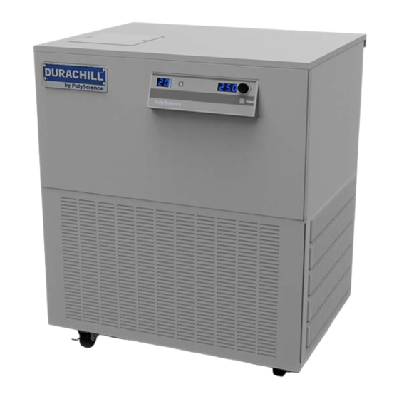
Introduction DuraChill Chillers provide cooling power for demanding applications and serve as an economical alternative to tap water cooling systems. All models feature a microprocessor-based controller, digital Temperature Display (°C or °F), one-touch set point display, and digital Pressure/Flow Rate Display (PSI, kPa, GPM, LPM) with push-Button selection. -
Page 5: General Safety Information
General Safety Information When installed, operated, and maintained according to the directions in this manual and common safety procedures, your Chiller should provide safe and reliable temperature control. Please ensure that all individuals involved in the installation, operation, or maintenance of this Chiller read this manual thoroughly prior to working with the unit. - Page 6 WARNING: Be sure to remove power from the equipment, reclaim the refrigeration charge, and relieve any residual pressure before cutting into the refrigeration system. WARNING: Do not attempt to operate leaking or damaged equipment. WARNING: Service should only be performed by fully qualified personnel. Extreme caution is required as hazards are present when servicing this equipment.
-
Page 7: Regulatory Compliance And Testing
Regulatory Compliance and Testing EC Low Voltage Directive 2006/95/EC EC Electromagnetic Compatibility Directive 2004/108/EC IEC 61010-1-2001 IEC 61326:2005 / EN 61326 : 2006 Unpacking Your Chiller is shipped in a special container. Retain the container and all packing materials until the unit is completely assembled and working properly. -
Page 8: Controls And Components
Controls and Components Control Panel Unit / Menu Select Button Temperature Units Pressure / Flow Rate Display Select / Set Knob Pressure / Flow Rate Units Power Button Temperature Display Front View Reservoir Plate Covert Reservoir Sight Glass Port (side of unit) Control Panel Air Filter Access (air-cooled... -
Page 9: Rear View
Rear View Power Switch Power Switch 110-275... -
Page 10: Installation And Startup
Installation and Startup WARNING: Be sure all power is OFF before proceeding. Site Requirements Ambient Temperature and Relative Humidity The Chiller is designed for indoor installation in ambient temperatures between 5° and 30°C (41° and 86°F); relative humidity should not exceed 80% (non-condensing). Location The Chiller should be installed on a strong, level surface. -
Page 11: External Piping
External Piping WARNING: All facility water connections must be made by a licensed plumber. General Considerations To maintain a safe workplace and avoid leaks, special care should be taken when choosing hoses and connectors for the Chiller. It is the user’s responsibility to ensure that the tubing and fittings connected to the Chiller are compatible with the fluid, temperature, and pressure being used. -
Page 12: Process Fluid Connections
Process Fluid Connections The Chiller has two internally threaded (0.75 inch ID NPT) fittings on the rear of the instrument housing for the process water connections. Two sets of adapters for 0.75 inch hose are supplied with the unit for connecting these fittings to the process piping. - Page 13 3. Set the Pressure / Flow Rate Display to read in either PSI or kPa (see Normal Operation, Selecting the Pressure / Flow Rate Display and Units). 4. Remove the insulation covering the pressure regulating valve cap and then remove the cap. There may be some coolant in the cap;...
-
Page 14: Process Coolant
Process Coolant Suitable Fluids WARNING: Use only fluids that comply with safety, health, and equipment compatibility requirements. Read the safety data sheet for the fluid being used carefully before use. The Chiller is designed to accommodate a variety of coolant fluids (water, glycol mixtures, etc). For most applications above 15°C (59°F), distilled water is satisfactory. -
Page 15: Electrical Power
Electrical Power WARNING: Make sure the main power switch is in the OFF position before connecting or disconnecting electrical power from the unit. Follow all applicable electrical and safety codes and procedures when connecting power to the unit. Electrical connections should be made by an authorized electrical installer. WARNING: Make certain that the electrical supply is the same voltage and frequency as your unit (see identification label). -
Page 16: Optional Signal Inputs/Outputs
Optional Signal Inputs/Outputs RS-232 / RS-485 Serial Output This option allows you to remotely control the Chiller and/or output temperature readings to an external recorder or other auxiliary device. The maximum communications distance for Chillers equipped with the RS232 option is 50 feet (15 meters). -
Page 17: Startup
Startup Facility Water Flow (water-cooled units only) 1. Open the valves to the facility water supply and return. 2. Check for leaks. Filling the Reservoir 1. Remove the reservoir cover plate (located on the top of the Chiller) and reservoir cap. 2. -
Page 18: Normal Operation
Normal Operation NOTE: The Chiller incorporates a special “lockout” feature that can be enabled to prevent unauthorized or accidental set point and other operational changes. This feature is described in detail under “Enabling / Disabling the Local Lockout.” It should not be enabled until all operational parameters have been set. Unit / Menu Temperature Units Select Button... -
Page 19: Selecting The Pressure / Flow Rate Display And Units
Selecting the Pressure / Flow Rate Display and Units The Chiller can be set up to display either fluid pressure (in PSI or kPa) or flow rate (in GPM or LPM). Pressing the Units/Menu Select Button briefly toggles through the available selections. NOTE: The metric pressure reading displayed must be multiplied by 100 for the actual kPa value. - Page 20 Menu Description Choices / Ranges Default Setting Item High Ambient Temperature Limit — Maximum ambient temperature limit. Displayed and settable only in ºC. Should the ambient temperature rise above the HA value, the audio and visual alarms will activate and the compressor, heater, +30 to 45ºC fan, and pump will turn off.
-
Page 21: High Temperature Limit (Hl)
High Temperature Limit (HL) This menu item serves two functions. First, it establishes the maximum allowable set point temperature and thus helps prevent an operator from inadvertently selecting a temperature set point above a pre-established value. Secondly, it serves as a high temperature alarm, automatically activating both audio and visual alarm indicators if the measured fluid temperature reaches the HL setting. -
Page 22: Minimum Flow Rate (Fl)
kPa x 100 NOTE: Chillers with positive displacement and turbine pumps also incorporate a built-in safety that automatically maintains fluid pressure below a valve-regulated pressure value. It maintains this maximum outlet pressure by diverting the flow of process fluid to the reservoir (i.e., begin internally recirculating the fluid). -
Page 23: Auto-Refrigeration Temperature (Af)
Auto-Refrigeration Temperature (AF) NOTE: This value is always displayed/set in °C. This menu item allows you to select the temperature at which refrigeration is activated. When the set point exceeds the auto-refrigeration temperature by more than 1.0°C, the cooling and the fan are turned off. To change the auto-refrigeration temperature, rotate the Select/Set Knob until the desired value is displayed. -
Page 24: Baud Rate (Pc)
Baud Rate (PC) This menu item allows you to establish the baud rate for serial communication. Allowable settings are 0 (no serial communication), 24 (2400 baud), 48 (4800 baud), 96 (9600 baud), and 192 (19200 baud). To change the displayed setting, rotate the Select/Set Knob until the desired baud rate is displayed. Press the Select/Set Knob or allow the display to time out to accept the displayed value. -
Page 25: Display, Alarm And Error Messages
Display, Alarm and Error Messages When certain conditions are detected, a message code flashes on the display and the local audio alarm sounds. Depending on the nature of the condition, power to various systems components, such as the compressor, heater, fan, and pump, is removed. When the condition is rectified, push the front panel Power Button or turn the Power Switch OFF then ON to clear the fault or error. - Page 26 Fault Code Description Action Required Alarm — Process fluid temperature is below the low temperature limit value for more than 25 seconds. Compressor, heater, and fan Low limit temperature are turned off; pump remains on. alarm To clear the fault, turn the unit OFF then ON using the front panel Power Button, and decrease the LL value.
-
Page 27: Enabling / Disabling The Local Lockout
Fault Code Description Action Required Alarm – Ambient temperature at front panel is higher than high ambient temperature limit. Occurs when ambient temperature exceeds the set ambient limit by 5°C or more. Compressor, heater, Front panel high ambient fan, and pump are turned off. temperature alarm Lower temperature in area where Chiller is located or increase high ambient temperature limit value. -
Page 28: Routine Maintenance And Troubleshooting
Routine Maintenance and Troubleshooting Routine Maintenance The Chiller is designed to require a minimum of periodic maintenance. Condenser, Air Vents and Reusable Filter To keep the system operating at optimum cooling capacity, the condenser, the air vents, and reusable filter should be kept free of dust and dirt. -
Page 29: Troubleshooting
Troubleshooting Many problems can be resolved by restoring the factory defaults. If this solves the problem, be careful when restoring your operational settings in order not to repeat the problem. To restore the factory default settings: 1. Place the Power Switch on the rear of the unit in the OFF position. Press and hold the Power Button on the front panel while returning the Power Switch to the ON position. -
Page 30: Diagnostic Mode
Diagnostic Mode NOTE: The Chiller must be set up to display temperature in °C in order to access the diagnostic mode. The Chiller incorporates a Diagnostic mode, which displays important operational information that can aid in troubleshooting. To access the Diagnostic mode, place the Power Switch on the rear of the unit in the OFF position and then return it to the ON position while pressing and holding the Select/Set Knob. -
Page 31: Technical Information
Technical Information Controller Specifications Temperature Set Point Resolution ±1.0°C Temperature Stability ±0.9°F (±0.5°C) Temperature Units °C or °F Pressure Units PSI or kPa Pressure Display Resolution 1 PSI / 0.1 kPa Flow Rate Units GPM or LPM Flow Rate Display Resolution 0.1 GPM / 1 LPM Performance Specifications –... -
Page 32: Electrical Specifications - Dca200 Chillers
CIRCUIT CIRCUIT AIR-COOLED OPERATING OPERATING OPERATING OPERATING BREAKER BREAKER BREAKER BREAKER AMPERAGE AMPERAGE AMPERAGE AMPERAGE SIZE SIZE SIZE SIZE DCA203D1/S1 21.9 34.4 DCA203D5/S5 20.5 DCA203D6/S6 22.9 35.4 DCA203D7/S7 21.4 33.9 DCA203C4 17.8 30.3 DCA203F 20.6 33.1 DCA203G Consult Factory DCA204D1/S1 18.8... -
Page 33: Performance Specifications - Dca300 & Dcw300 Chillers
Performance Specifications – DCA300 and DCW300 Chillers 3 HP DCA300 DCW300 Air-Cooled Water-Cooled Compressor Nominal HP Temperature Range °F 41° to 95°F (without heater option) °C 5° to 35°C Temperature Range °F 41° to 194°F (with heater option) °C 5° to 90°C Temperature Stability °F ±0.9°F... -
Page 34: Electrical Specifications - Dca300 & Dcw300 Chillers
Electrical Specifications — DCA300 & DCW300 Chillers 3000 WATT HEATER 7500 WATT HEATER 9000 WATT HEATER NO HEATER FUSE / FUSE / FUSE / FUSE / 3 HP MAX. MAX. MAX. MAX. CIRCUIT CIRCUIT CIRCUIT CIRCUIT AIR-COOLED OPERATING OPERATING OPERATING OPERATING BREAKER BREAKER... - Page 35 NO HEATER 3000 WATT HEATER 7500 WATT HEATER 9000 WATT HEATER 3 HP FUSE / FUSE / FUSE / FUSE / MAX. MAX. MAX. MAX. WATER- CIRCUIT CIRCUIT CIRCUIT CIRCUIT OPERATING OPERATING OPERATING OPERATING COOLED BREAKER BREAKER BREAKER BREAKER AMPERAGE AMPERAGE AMPERAGE AMPERAGE...
-
Page 36: Pump Performance
Pump Performance Specifications subject to change without notice. 110-275... -
Page 37: Rs-232 / Rs-485 Communications
RS-232 / RS-485 Communications Serial Connector — A 9-pin D-connector (optional) is provided on the back panel of the Chiller for RS232 / RS485 data communication. A serial cable that uses only the following pins should be used to connect the Chiller to the computer: RS-232 RS-485... -
Page 38: Equipment Disposal (Weee Directive)
Equipment Disposal (WEEE Directive) This equipment is marked with the crossed out wheeled bin symbol to indicate it is covered by the Waste Electrical and Electronic Equipment (WEEE) Directive and is not to be disposed of as unsorted municipal waste. Any products marked with this symbol must be collected separately, according to the regulatory guidelines in your area. -
Page 39: Polyscience Chiller Fluids
Warranty NOTE: The Warranty on DuraChill and other custom-designed products applies only to the original end user and cannot be transferred or sold to another end user without written consent from the manufacturer. The manufacturer’s warranty is one year for parts and labor and two years for parts. Please contact your supplier for additional warranty details and service contract information. -
Page 40: Appendix
Appendix Flow Diagram – Air-Cooled Chillers 110-275... -
Page 41: Flow Diagram - Water-Cooled Chillers
Flow Diagram – Water-Cooled Chillers 110-275... -
Page 42: Wiring Diagram - 208-230V, 1 Phase Air-Cooled Chillers
Wiring Diagram – 208-230V, 1 Phase Air-Cooled Chillers 110-275... -
Page 43: Wiring Diagram - 208-230V, 380-460V 3 Phase Air- And Water-Cooled Chillers
Wiring Diagram – 208-230V, 380-460V 3 Phase Air- and Water-Cooled Chillers 110-275...
Need help?
Do you have a question about the DCA203D1/S1 and is the answer not in the manual?
Questions and answers