Table of Contents
Advertisement
Advertisement
Table of Contents

Related Manuals for jenway 3510

Summary of Contents for jenway 3510
-
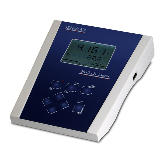
Page 1: Instruction Manual
Temperature Meter Model 3510 Instruction Manual 351 050/REV C/02-17... - Page 3 Safety Please read this information carefully prior to installing or using this equipment. 1. The unit described in this manual is designed be operated only by trained personnel. Any adjustments, maintenance and repair must be carried out as defined in this manual, by a person qualified to be aware of the hazards involved.
- Page 4 Bitte lesen Sie diese Hinweise vor Installation oder Gebrauch dieser Ausrüstung sorgfältig durch. 1. Das in diesem Handbuch beschriebene Gerät darf nur von geschultem Personal bedient werden. Alle Anpassungen, Wartungsarbeiten und Reparaturen müssen entsprechend der Vorgaben in diesem Handbuch und von einer kompetenten Person, die mit den damit verbundenen Gefahren vertraut ist, durchgeführt werden.
- Page 5 5. Nel caso in cui si sospetti che la salute possa essere pregiudicata in qualsiasi modo, disattivare l'unità per renderla inutilizzabile. Qualsiasi condizione di errore deve essere immediatamente segnalata al responsabile per la manutenzione. Lea esta información atentamente antes de instalar o utilizar este equipo. 1.
-
Page 6: Table Of Contents
Model 3510 pH/mV/Temperature Meter Operating Manual Contents Section 1 Introduction Instrument Description Instrument Specification Section 2 Installation Unpacking Installation Displays Keypad Inputs/Outputs Section 3 Operation Theory of pH measurement pH Measurement Preparation of Buffer Solution Solution Temperature Values Good Practice Guidelines... -
Page 7: Introduction
The meter supports 1, 2 or 3 point pH calibration on either manually entered pH buffer values or automatically temperature compensated buffers to DIN, JIS and NIST standards and Jenway buffers supplied with the instrument. Up to 3 decimal place resolution is available. The 3510 includes a 32 reading memory facility. -
Page 8: Installation
The Model 3520 is supplied ready to use. Connect the ATC (if required) and the pH electrode to the The Model 3510 is supplied ready to use. Connect the ATC (if required) and the pH electrode to the rear panel Temp and pH sockets. -
Page 9: Displays
2.3 Display Fig. 2.3.1 – Display Symbol – displayed during set-up of instrument parameters. Primary display – 4½ digit. Provides direct readout in pH and millivolts of samples and standards. Mode annunciators – shows selected measurement mode; pH, mV (Absolute and Relative). Calibration point –... -
Page 10: Keypad
2.4 Keypad 2.4.1 Keypad 1. ESC used to switch the instrument on and to place into standby mode (only if power supply lead remains connected to the instrument). Also used to escape/exit a mode. 2. CAL / CLR used to select and perform a calibration sequence. This key is also used to clear readings from Memory. -
Page 11: Inputs/Outputs
2.5 Inputs/Outputs Fig. 2.5.1 – Rear panel layout 1. Ref Socket 2mm pin socket. Connection socket for separate reference electrode. When performing measurements with some pH and ion selective electrodes a separate reference electrode is needed. 2. pH Socket BNC type socket which allows combination pH or redox electrodes to be used. -
Page 12: Operation
If the liquid junction is inefficient then measurement will be inaccurate. It is common for the reference electrode to be incorporated into the pH electrode. It is then called a combination electrode. The Model 3510 meter is supplied with a combination electrode. 351 050/REV B/09-06... -
Page 13: Preparation Of Buffer Solution
The voltage developed by each individual pH electrode in the presence of a known hydrogen ion concentration is theoretically predictable, but in practise deviations from the theoretical value can be expected. These deviations will change slowly during the life of an electrode. It is therefore essential to routinely calibrate the system using solutions with a known and constant pH value. -
Page 14: Good Practice Guidelines
3.5 Good Practice Guidelines The types of electrodes are many and various. For the majority of tests carried out on aqueous solutions, with a reasonable ionic strength; at ambient temperatures and with limited use in strongly acidic or alkaline solutions, the standard glass or epoxy bodied combination electrode is ideal. For other applications a more suitable pH/reference electrode pair may be required;... -
Page 15: Instrument Set-Up
MODE menu. Any parameters not saved will remain as defaults or previous setting. 3.6.1 Number of calibration points entry I, 2 or 3 point calibration is possible on the 3510. To set these parameters: Select SETUP mode on the display using the Left arrow key. - Page 16 The secondary display will show BUFFER and will then scroll BUFFER TYPE after 10 seconds. Select the type of buffer from the options available by scrolling through the list using the Up/Down arrows – AUTO, MAN, JIS, NIST or DIN. (AUTO relates to the Jenway buffer types supplied with the instrument).
- Page 17 If a 2 or 3 point calibration is being performed the display will move on to the 2 and then 3 point calibration buffer set up screens. The correct values should be entered and saved as for the 1 point calibration. When all chosen buffer types have been entered and confirmed the instrument display will update to show the next set up menu option.
- Page 18 3.6.4 Temperature units The display will show: The secondary display will show UNITS and will then scroll TEMPERATURE UNITS after 10 seconds. Select °C or °F using the Up/Down arrows. The Left/Right arrow keys and the CAL/CLR key have no function during this set up. Symbol will flash while adjustment is being made.
- Page 19 3.6.6 Baud Rate For full details relating to serial protocol refer to Section 6 of this manual. The display will show: The secondary display will show BAUD and will then scroll SERIAL PORT BAUD RATE after 10 seconds. Select the required baud rate (9600 or 1200) using the Up/Down arrow keys. The data bits and parity will automatically adjust as the baud rate is selected.
-
Page 20: Ph Calibration
3.7 pH Calibration 3.7.1 Calibration with Manual Temperature Compensation To exit the calibration sequence at any time press the ESC key. This will cancel the pH calibration and return the instrument to the MODE menu. Note: Buffer solutions should be carefully prepared as per the manufacturers instructions. When using manual temperature compensation (no ATC probe fitted) the solution temperature should be measured and the value entered in the set up menu prior to calibrating the instrument (refer 3.6.5). - Page 21 If a successful calibration has been performed the secondary display will momentarily show CAL OK. The instrument will then update the display. The display will then show the next part of the calibration sequence if a 3 point calibration has been selected. If a 2 point calibration only is required the instrument will return to the main measuring screen.
- Page 22 3.7.2 Calibration with Automatic Temperature Compensation To exit the calibration sequence at any time press the ESC key. This will cancel the pH calibration and return the instrument to the MODE menu. Note: Buffer solutions should be carefully prepared as per the manufacturers instructions. 1.
-
Page 23: Error Codes
4. CAL 3 Immerse the electrode(s) in the third buffer solution and allow the instrument to stabilise. When no change in the least significant display digit is detected over a five second period the endpoint symbol will be displayed. Press the CAL or STO key. If a successful I point calibration has been performed the secondary display will momentarily show CAL OK. - Page 24 3.9 Millivolt Mode Absolute Millivolts When this mode is selected the unit will display the actual voltage developed by the electrode when it is immersed in a solution containing ions to which the electrode is sensitive. The electrode may be a combination type or a suitable sensing/reference pair, depending on the specific test being carried out.
-
Page 25: Performing Measurements
3.10 Performing Measurements To perform measurements in pH, mV or temperature modes the following should be carried out: mV Measurement a) Connect the electrode to the unit via the BNC socket on the rear panel. If a separate reference electrode is to be used, this should be connected to the Ref socket. b) Select mV mode using the Up/Down arrows. -
Page 26: Results Storage And Display
3.11 Results storage and display To store the current displayed result press the STO key. The instrument display will momentarily show STORED on the secondary display. The memory location will be given on the status display. Up to 32 results can be stored. Each result will be stored in the next available memory location. The instrument will store: Primary pH or mV readings Temperature readings and the unit of measurement (°C or °F) -
Page 27: Maintenance
Maintenance 4.1 General The Model 3510 is designed to give optimum performance with minimum maintenance. It is only necessary to keep the external surfaces clean and free from dust. To give added protection when not in use the unit should be switched off and covered with the optional dust cover (060 406). -
Page 28: Optional Accessories Optional Accessories
Optional Accessories Optional Accessories Optional Accessories The following list of items are available as optional accessories for use with the Model 3510: The following list of items are available as optional accessories for use with the Model 3520: 5.1 Optional Accessories The following list of items are available as optional accessories for use with the Model 3520: 5.1 Optional Accessories... -
Page 29: Interfacing
The Bi-directional RS232 interface is available on the rear panel 9 way D type connector. The connections are as follows: DCD 1 - LINKED TO DTR AND DSR RXD 2 - INPUT TO 3510 TXD 3 - OUTPUT FROM 3510 DTR 4 - LINKED TO DCD AND DSR... -
Page 30: Keypad Emulation
The Model 3510 supports both hardware (CTS/RTS) flow control and software XON/XOFF flow control. Pressing the PRINT key outputs from the RS232 interface. Sending an ASCII “D” to the 3510 causes a printout of the current displayed reading plus sample number. -
Page 31: Printing
6.4 Printing A 32 column serial printer (037 701) is available for use with the Model 3510. Connect the printer via the cable supplied with the printer to the 9 way socket located on the rear panel of the instrument. - Page 32 6.4.1 Example Printout 3510 Header printout 3510 Results printout 351 050/REV B/09-06...
-
Page 33: Troubleshooting
Usage of other units will cause the 3510 not to operate. Drifting erratic readings Electrode fault Use BNC cap to test 3510 (see 7.2) Replace electrode. Cannot calibrate Electrode Fault Use BNC cap to test 3510 (see 7.2) Replace electrode. -
Page 34: Functional Checks
4) Select mV mode the display should read ±1. If the mV reading is greater than ±1mV perform a reset (refer Section 7.3). To make measurements from this point refit the ATC probe and pH probe and calibrate the 3510 using fresh buffer solutions (see section 3.6). - Page 35 and so we cannot guarantee that interference will not This product meets the applicable EC harmonised standards for radio frequency occur in practice. Where there is a possibility that injury, interference and may be expected not to damage or loss might occur if equipment malfunctions interfere with, or be a ected by, other equipment with due to radio frequency interference, or for general similar quali cations.
- Page 36 Cole-Parmer Ltd Beacon Road, Stone, Staffordshire, ST15 0SA, United Kingdom Tel: +44 (0)1785 812121 Email: cpinfo@coleparmer.com Web: www.jenway.com...
Need help?
Do you have a question about the 3510 and is the answer not in the manual?
Questions and answers