Table of Contents
Advertisement
®
Installation, Operation and Maintenance Manual
Please read and save these instructions for future reference. Read carefully before attempting to assemble,
install, operate or maintain the product described. Protect yourself and others by observing all safety
information. Failure to comply with instructions could result in personal injury and/or property damage!
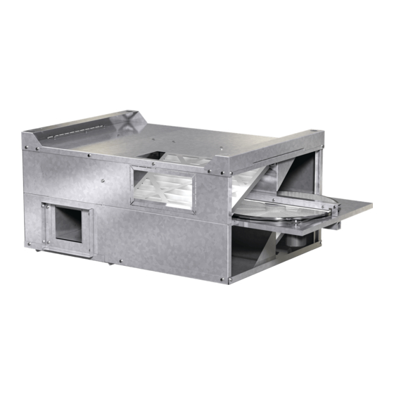
Model MiniVent-450 & 750
General Safety Information
Only qualified personnel should install this system.
Personnel should have a clear understanding of these
instructions and should be aware of general safety
precautions. Improper installation can result in electric
shock, possible injury due to coming in contact with
moving parts, as well as other potential hazards.
Other considerations may be required if high winds
or seismic activity are present. If more information
is needed, contact a licensed professional engineer
before moving forward.
DANGER
Always disconnect power before working on or near
this equipment. Lock and tag the disconnect switch
or breaker to prevent accidental power up.
CAUTION
When servicing the unit, the internal components
may be hot enough to cause pain or injury. Allow
time for cooling before servicing.
CAUTION
Precaution should be taken in explosive
atmospheres.
®
Energy recovery wheels are certified by the AHRI Air-to-Air Energy Recovery Ventilation Equipment
Certification Program in accordance with AHRI Standard 1060. Actual performance in packaged
equipment may vary.
Certified Ratings are available in the Certified Product Directory at www.ahridirectory.org
Energy Recovery Ventilators
1. Follow all local electrical and safety codes, as well
as the National Electrical Code (NEC), the National
Fire Protection Agency (NFPA), where applicable.
Follow the Canadian Electric Code (CEC) in
Canada.
2. All moving parts must be free to rotate without
striking or rubbing any stationary objects.
3. Unit must be securely and adequately grounded.
4. Do not spin fan wheel faster than maximum
cataloged fan RPM. Adjustments to fan speed
significantly affects motor load. If the fan RPM is
changed, the motor current should be checked to
make sure it is not exceeding the motor nameplate
amps.
5. Do not allow the power cable to kink or come in
contact with oil, grease, hot surfaces or chemicals.
Replace cord immediately if damaged.
6. Verify that the power source is compatible with the
equipment.
7. Never open access doors to the unit while it is
running.
Energy Recovery Ventilators • MiniVent
Part #459023
1
Advertisement
Table of Contents


Need help?
Do you have a question about the MiniVent-450 and is the answer not in the manual?
Questions and answers
Is this unit BacNet compatable?