Table of Contents
Advertisement
Quick Links
Advertisement
Table of Contents

Summary of Contents for OPAL Holding OD5
- Page 1 User Manual Version EV1.140b - 1 -...
- Page 2 EN50081-1 (EN55022 CLASS A) and EN61000-4-2/-3/-4/-5/-6/-8/-11 (IEC Teil 2,3,4). The equipment also tested and passed in accordance with the European Standard EN55022 for the both Radiated and Conducted emissions limits. THE OD5 THERMAL PRINTER TO WHICH THIS DECLARATION RELATES IS IN CONFORMITY WITH THE FOLLOWING STANDARDS EN55022 : 1998,CLSPR 22 , Class A / EN55024 : 1998 IEC 61000-4 Serial / EN61000-3-2 : 2000 / EN 61000-3- 3 : 1995 / CRF 47, Part 15/CISPR 22 3rd Edition : 1997,Class A / ANSI C63.4 : 2001 / CNS 13438,CISPR...
-
Page 3: Table Of Contents
CHAPTER 1 - BARCODE PRINTER.................4 1-1. I ............................4 NTRODUCTION 1-2. P ............................4 RINTER ODELS 1-3. P ...........................4 RINTER CCESSORIES 1-4. G ........................5 ENERAL PECIFICATIONS 1-5. C ........................6 OMMUNICATION NTERFACE 1-6. P ............................7 RINTER ARTS CHAPTER 2 - PRINTER INSTALLATION ................8 2-1. -
Page 4: Chapter 1 - Barcode Printer
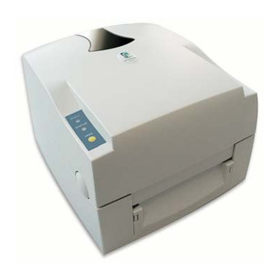
1-1. Introduction The OD5 is a desktop thermal transfer / direct thermal label printer. With plastic outer casing, the OD5 is designed to be a lightweight and an economic printer for large variety of printing requirement. Its features are as... -
Page 5: General Specifications
1-4. General Specifications Model Name Resolution 203 dpi (8 dot/mm) Print Mode Thermal Transfer / Direct Thermal 16 Bit Sensor Location Moveable, center aligned Sensor Type Reflective Sensor Detection Type: Label gap, black mark, and punch hole sensing. Detection: Label length auto sensing and / or program command setting Print Speed 2~4 IPS Standard Print Length... -
Page 6: Communication Interface
1-5. Communication Interface Parallel Interface Interface cable : Parallel cable compatible with IBM PC Pin out : See below PIN NO. FUNCTION TRANSMITTER /Strobe host / printer Data 0-7 host /Acknowledge printer Busy printer /Paper empty printer /Select printer /Auto-Linefeed host / printer Signal Gnd Chasis Gnd... -
Page 7: Printer Parts
1-6. Printer Parts Please use the following diagrams to identify each printer part. Cover Open Button 11 LED Light (Ready) 21 Power Socket Top Cover 12 LED Light (Status) 22 USB Port Label Roll Core 13 FEED Key 23 Parallel Port Ribbon Rewind Wheel 14 Print Line Adj. -
Page 8: Chapter 2 - Printer Installation
Chapter 2 - Printer Installation This printer model has the following print modes: Thermal Transfer (TT): When printing, ribbon must be installed to transfer the print contents onto the media. Direct Thermal (DT): When printing, no ribbon is necessary; it only requires direct thermal media. 2-1. -
Page 9: Ribbon Installation
2-2. Ribbon Installation Open the top cover by pressing the Cover Open Buttons on both sides. Loosen and then lift the upper print mechanism by pressing the locking tenons. Take out the ribbon supply shaft and rewind shaft. Place the new ribbon roll onto the ribbon supply shaft. -
Page 10: Label Roll Core Installation Instruction
2-3. Label Roll Core Installation Instruction (A) 1” roll core installation instruction (B) 1.5” roll core installation instruction (C) 3” roll core installation instruction - 10 -... -
Page 11: Card / Hang Tags Installation
2-4. Card / Hang tags Installation When installing cord tags, the tag hole must align with the sensor arrow (as indicated in Photo 1), then use the Label Guide to secure the tags. Tag hole position Sensor Detection Position (Photo 1) 2-5. - Page 12 3. Peel off the first label, and feed the liner through the roller and the peel off bracket. 4. Pull to level the label. 5. Flip to close the stripper module. 6. Close the print mechanism, and then press the FEED key. - 12 -...
-
Page 13: Stripper Installation Diagram
2-6. Stripper Installation Diagram LABEL LINER LABEL LINER - 13 -... -
Page 14: Pc Connection
2-9. PC Connection Please make sure the printer is powered off. Take the power cable, plug the cable switch to the power socket, and then connect the other end of the cable to the printer power socket. Connect the cable to the parallel port on the printer and on the PC. Power on the printer. -
Page 15: Chapter 3 - Options Installation
Chapter 3 - Options Installation 3-1. Cutter Parts 27 Cutter Module 28 Screw (TAP 3*8) x 2pcs (Note 1) Please power off the printer before installing the cutter module. (Note 2) Do not cut self-adhesive labels! The traces of adhesive will pollute the rotary knife and impair safe operation! The service life of the cutter is 500,000 cuts with 160g/m... - Page 16 Hold the stripper module and loose the screws. Lift/take off the stripper module. Open the mechanism by pressing the Locking Tenon, plug in the cable connector of the cutter module (26) onto the switchboard socket. Note: There are 2 sockets on the converting boards (one is for stripper installation, another is for cutter installation), before...
- Page 17 Hold the cutter module and lock it with the two side screws (27). After the screws are locked, flip close the cutter module. 10. Close the mechanism to complete the cutter module installation. - 17 -...
-
Page 18: Extended Memory Parts
3-3. Extended Memory Parts Extended Memory Card PCB Pillar x 2pcs [NOTE]: Please power off the printer before installing the extended memory. - 18 -... -
Page 19: Extended Memory Installation
3-4. Extended Memory Installation 1. Open the top cover by pressing the Cover Open Buttons on both sides. 2. Take off the media roll spindle. Open and remove the plastic cover on the inner base. 3. Secure the PCB pillar onto the main board. - Page 20 4. Check the pins where the memory is to be connected to, then plug the memory card onto the main board. Note: Please make sure the aperture on the connector and the pins match, otherwise when too much force is applied onto the memory card, there’s a possibility that the pins may get damaged.
-
Page 21: Control Panel
4. Control Panel 4-1. LED Status LED colour Beep Status Description READY Green Normal Ready for operation Status STATUS READY Red (flashing) Printer prints Selftest Label, point 4.3.2 Selftest STATUS Orange READY Orange (flashing) Auto Sensing Printer is in selfrecognition Mode, point Mode 4.3.4 STATUS... -
Page 22: Feed Key
4-3. Operation With the OD5 all important functions can be activated or alternatively completed with a certain key combination. For this you have to switch off the printer. Afterwards you keep the FEED key pressed and switch the printer on. - Page 23 4-3-2. Selftest Label The self check function makes it easier for the user to find out if the the printer works correctly. In this mode the printer prints out a self check side with each press on the FEED key. In order to stop the self check during the procedure, please switch off the printer.
-
Page 24: Dump Mode
4-3-3. Hexdump Mode If label settings and the printed result do not match, please check whether any disturbances arose during the data communication between printers and PC with the assistance of the Hexdump mode. If the printer receives for example eight instructions, but doesn’t perform these instructions, please print out the instructions only. - Page 25 (Users guide: Point 4.2) Install the printer driver (when using USB the USB driver has to be installed first). (Users guide: OD5 Ethernet Installation guide, USB driver Installation guide) Set the printer settings of the printer driver suiting to your label.
-
Page 26: Error Messages
4-3-7. Error Messages LED Display Audio Description Solution Message Signal Ready Status Print head is 2 x 4 Audio The printer mechanism is not closed Open the printer mechanism and opened Signals correctly. close it again. Falls the temperature the printer Entering the High temperature at the print head. -
Page 27: Chapter 5 - Maintenance And Adjustment
Chapter 5 - Maintenance and Adjustment 5-1. Thermal Print Head Cleaning Unclear printouts (some parts unable to print) may be caused by dusty print head, ribbon stain, or label liner glue, therefore when printing, it’s necessary to keep the top cover closed. Also, check and prevent paper/label from being stained or dusty to ensure print quality and to prolong the print head life. -
Page 28: Print Line Adjustment
5-3. Print Line Adjustment Use print head adjusting gear to adjust the contacting surface between print head and label. To get better printing balance and quality. 1. When turning print head adjusting gear counter- clockwise (as arrow 1 shows), print head would move in a direction where arrow A is. -
Page 29: Troubleshooting
5-5. Troubleshooting Problem Recommended Solution Power on the printer, but the LED Check the power connector does not light up LED light turns red (power/status) Check for software setting or program command errors after printing stops Replace with suitable label or ribbon Check if label or ribbon is all out Check if label is jammed/tangled up Check if mechanism is closed (Thermal Print Head not positioned...
Need help?
Do you have a question about the OD5 and is the answer not in the manual?
Questions and answers