Table of Contents
Advertisement
Owner's Manual
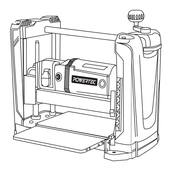
12-1/2" THICKNESS PLANER
QUESTION...
1•877•393•7121
1•847•780•6120
Visit us on the web at www.powertecproducts.com
You will need this manual for safety instructions, operating procedures, and warranty.
Put it and the original sales invoice in a safe, dry place for future reference.
Model No. PL1251
15-0720
Advertisement
Table of Contents

Related Manuals for PowerTec PL1251


Summary of Contents for PowerTec PL1251
- Page 1 Model No. PL1251 Owner’s Manual 12-1/2" THICKNESS PLANER QUESTION... 1•877•393•7121 1•847•780•6120 Visit us on the web at www.powertecproducts.com You will need this manual for safety instructions, operating procedures, and warranty. Put it and the original sales invoice in a safe, dry place for future reference.
-
Page 2: Table Of Contents
TABLE OF CONTENTS PRODUCT SPECIFICATIONS SECTION PAGE SAFETY RULES Horsepower (Maxmum Developed)......2 HP Voltage................120 V Work Preparation Work Area Preparation Amperes................15 A Tool Maintenance Hertz................60 Hz Tool Operation Phase................Single ASSEMBLY Motor RPM............17,500 RPM Table Size...........12-1/2”×9-5/16” Unpacking Install Dust Chute Blade Width...............12mm Install Elevation Crank Handle Maximum Depth of Cut..........3/32”... -
Page 3: Safety Rules
SAFETY RULES TOOL MAINTENANCE WARNING • Turn the machine "OFF", and disconnect the machine For your own safety, read and understand all warnings from the power source prior to inspection. and operating instructions before using any tool or • Maintain all tools and machines in peak condition. Keep equipment. -
Page 4: Assembly
ASSEMBLY UNPACKING Figure 1 Unpacking • Check for freight damage before opening the package. If freight damage is noticed, file a claim with the carrier immediately. • Check to ensure all parts are accounted for. If any parts are missing, please contact the customer service center at 1-877-393-7121. -
Page 5: Install Elevation Crank Handle
INSTALL ELEVATION CRANK HANDLE POWER SOURCE Refer to Figure 2 and 3 WARNING • The planer handle can be installed to the top-right of the planer. Do not connect to the power source until the machine is • Insert handle onto elevation screw top. completely assembled. -
Page 6: Extension Cords
Extension Cord Length Figure 4 - 3-Prong Receptacle Wire Size ....... . A.W.G. Up to 25 ft. -
Page 7: Operation
OPERATION • There is an elevation scale at the front of right side panel. WARNING It has a pointer with English and Metric scale. The reading is the height of cutterhead from the table For our own safety, read the entire operating manual and platform. -
Page 8: Circuit Breaker
NOTE: When the machine is not in use, the machine position. Then press the circuit breaker reset button next should be locked in the “OFF” position to prevent to the main switch. unauthorized use. BEFORE OPERATING THE PLANER • To lock the machine, turn the switch to the “OFF” •... -
Page 9: Operate The Planer
• Stop pushing or pulling the workpiece once it is OPERATE THE PLANER MACHINE engaged by the infeed roller. • Always use protective safety wear and observe safety • The infeed roller will move the workpiece automatically rules. through the planer. •... -
Page 10: Maintenance
MAINTENANCE Figure 9 WARNING Turn the switch to the OFF position and disconnect the machine from power source before any maintenance. CHECK AND REPLACE THE BLADES Refer to Figure 9 and 10 • Locate the blade cover on the back of planer. Loosen and remove thumb screws from blade guard. -
Page 11: Adjust Rollercase Level
ADJUST ROLLERCASE LEVEL CLEAN AND LUBRICATION Refer to Parts Illustration • Vacuum the planer machine to remove wood chips, saw The rollercase level is checked in factory and should work dust, and debris. properly. However, it can become out of alignment •... -
Page 12: Troubleshooting
TROUBLESHOOTING SYMPTON POSSIBLE CAUSE(S) SOLUTIONS Motor will not start 1. Low voltage 1. Check power supply for proper voltage 2. Short circuit in line cord or plug 2. Inspect line cord and plug for faulty insulation or shorted connection 3. Short circuit in motor 3. - Page 13 SYMPTON POSSIBLE CAUSE(S) SOLUTIONS Difficulties in adjusting 1. Worn elevation screws 1. Release rollercase lock rollercase elevation 2. Dirty elevation screws or columns 2. Replace elevation screws 3. Dirty chains or sprockets 3. Clean and lubricate elevation screws and 4. Rollercase is not positioned level columns with planer base 4.
-
Page 14: Parts Illustration
12-1/2" THICKNESS PLANER PARTS ILLUSTRATION Figure 11... - Page 15 12-1/2" THICKNESS PLANER PARTS LIST Key No. Part No. Description Specification Key No. Part No. Description Specification PL1250001 Pan Head Screw M8*16 57-1 PL1250092.1 Subsidiary Column PL1251001 Portable Sheath PL1250100 Hex nut PL1251002 Left Cap PL1251035 Base PL1251003 Roller Ø20×2.0T×389L PL1250102 Bearing 6000ZZ...
-
Page 16: Warranty
30- DAY SATISFACTION GUARANTEE POLICY During the first 30 days after the date of purchase, if you are dissatisfied with the performance of this POWERTEC tool for any reason, you may return the tool to the retailer from which it was purchased for a full refund or exchange. You must present proof of purchase and return all original equipment packaged with the original product. - Page 17 ADDITIONAL LIMITATIONS To the extent permitted by applicable law, all implied warranties, including warranties of MERCHANTABILITY or FITNESS FOR A PARTICULAR PURPOSE, are disclaimed. Any implied warranties, including warranties of merchant- ability or fitness for a particular purpose, that cannot be disclaimed under state law are limited to one year from the date of purchase.
- Page 20 Southern Technologies, LLC 3816 Hawthorn Court, Waukegan, IL 60087...
Need help?
Do you have a question about the PL1251 and is the answer not in the manual?
Questions and answers