
Related Manuals for McQuay AGS 225D


Summary of Contents for McQuay AGS 225D
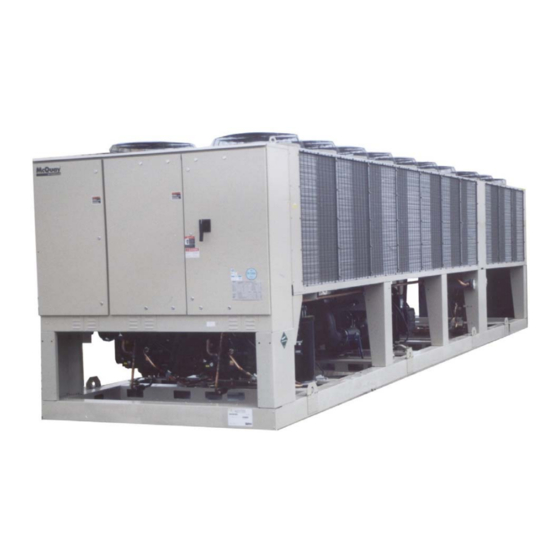
- Page 1 Operating Manual OM AGSD-2 Group: Chiller Part Number: 331375401 Date: July 2007 Supercedes: OM AGSD-1 Air-Cooled Screw Compressor Chiller AGS 225D through AGS 450D Software Version AGSG30101D 60 Hertz, R-134a...
-
Page 2: Table Of Contents
Manufactured in an ISO Certified facility Information in this manual covers the McQuay International products at the time of publication and we reserve the right to make changes in design and construction at anytime without notice. ®™ The following are trademarks or registered trademarks of their respective companies: BACnet from ASHRAE; L... - Page 3 This manual provides setup, operating, and troubleshooting information for the McQuay MicroTech ΙΙ® controller for Model AGS-D vintage, air-cooled, rotary screw compressor chillers. Please refer to the current version of the installation and maintenance manual IMM AGSD (available on www.mcquay.com) for information relating to the unit itself.
-
Page 4: Controller Features
Building Automation System (BAS) communication capability via L ORKS Modbus®, or BACnet® standard protocols for all BAS manufacturers-simplified with McQuay’s Protocol Selectability™ feature. • Pressure transducers for direct reading of system pressures. Preemptive control of low evaporator pressure conditions and high discharge temperature and pressure to take corrective action prior to a fault trip. -
Page 5: General Description
General Description Control Panel Layout The control panel is located on the front of the unit, to the left of the power panel. Figure 1, Control Panel Components Expansion Valve Circuit Breakers Drivers MicroTech II Controller, CP1 MicroTech II Controller, CP2, On Three-Compressor Units Only... -
Page 6: Definitions
Definitions Active Setpoint The active setpoint is the setting in effect at any given moment. This variation occurs on setpoints that can be altered during normal operation. Resetting the chilled water leaving temperature setpoint by one of several methods, such as return water temperature, is an example. - Page 7 High Saturated Condenser – Hold Value High Cond Hold Value = Max Saturated Condenser Value – 5 degrees F This function prevents the compressor from loading whenever the pressure approaches within 5 degrees of the maximum discharge pressure. The purpose is to keep the compressor online during periods of possibly temporary elevated pressures.
- Page 8 Soft Loading is a configurable function used to ramp up the unit capacity over a given time period, usually used to influence building electrical demand by gradually loading the unit. Setpoint Solid state starter as used on McQuay screw compressors. Suction Superheat Suction superheat is calculated for each circuit using the following equation: Suction Superheat = Suction Temperature –...
-
Page 9: Component Description
Component Description Hardware Structure The controllers are fitted with a 16-bit microprocessor for running the control program. There are controller terminals for connection to the controlled devices (for example: solenoid valves, expansion valves, chilled water pumps). The program and settings are saved permanently in FLASH memory, preventing data loss in the event of power failure without requiring a back-up battery. -
Page 10: System Architecture
System Architecture • One large controller (CP1) is used on 2 circuit chillers (AGS 225 through 300) and a second large controllers (CP2) is added on 3 circuit chillers (AGS 330 through 450). • Expansion I/O boards are used and communicate via a tLan (J23). Two are used on 2 circuit chillers and four are used on 3 circuit chillers. -
Page 11: Sequence Of Operation
Sequence of Operation Figure 4, Unit Sequence of Operation (see Figure 4 for circuit sequence of operation) Unit power up The chiller may be disabled via the unit switch, the remote switch, the keypad enable setting, or the BAS network. In addition, the chiller will be disabled if both Unit in Off state circuits are disabled, either because of an alarm or the circuit pumpdown switch on each circuit, or if there is a unit alarm. - Page 12 The first circuit will load and unload as needed in an attempt to satisfy the load. It will eventually get to a point where it is considered to be at full load. A circuit is at Load/unload as needed to full load when it reaches 75% slide target, it reaches the max slide target setting, or satisfy load.
- Page 13 Figure 5, Circuit Sequence of Operation Unit power up When the circuit is in the Off state the EXV is closed, compressor is off, and all fans are off. Circuit is in Off state If the compressor is ready to start when needed, the circuit status will be Off:Ready.
- Page 14 Off Conditions Power is supplied to the power section of the electric panel. The standard power connection is two (or three on models 330 to 450) separate sources, one to each circuit. Optionally, the power may be supplied to a single power connection, either a power block or optional disconnect switch.
- Page 15 The electronic expansion valves are operated by the MicroTech II controller to maintain precise refrigerant control to the evaporator at all conditions. Standard FanTrol Condenser Fan Control When the compressor starts, a number of fans may be started, depending on the OAT and the Forced Fan setpoints.
- Page 16 Figure 6, AGS-D Piping Schematic DISCHARGE DISCHARGE RELIEF SCHRADER FLOW TRANSDUCER TEMP. SENSOR DISCHARGE VALVE SCHRADER (WH1, WH2) VALVE (WD1, WD2) TUBING VALVE DISCHARGE (HEADER) (MOUNTED ON SUCTION VALVE CHECK VALVE BODY AT BACK SEAT PORT) CHARGING CHARGING VALVE FLOW VALVE CHARGING TRANSDUCER...
-
Page 17: Controller Operation
Controller Operation CP1 Inputs/Outputs I/O for the unit control and for circuits one and two are found on CP1. Analog Inputs Description Signal Source Normal Range Slide Load Indicator #1 4-20 mA Current 1 to 23 mA Slide Load Indicator #2 4-20 mA Current 1 to 23 mA Evaporator Pressure #1... -
Page 18: Expansion I/O Controller 1
Digital Outputs Description Output OFF Output ON SSS Enable Compressor Off Compressor On SV Load Load SV Unload Unload Open SV Liquid Line Enabled Fan motor 11/VFD enable Fan on Fan motor 12 Fan on Fan motor 13/14 Fans on SSS Enable Compressor Off Compressor On... -
Page 19: Expansion I/O Controller 4
Expansion I/O Controller 4 EXB4 is connected to CP1 for additional I/O. Analog Inputs Description Signal Source Expected Range Chilled Water Reset 4-20 mA Current 4 to 20 mA Demand Limit 4-20 mA Current 4 to 20 mA Oil Pressure #1 4-20 mA Current 3 to 22 mA Oil Pressure #2... -
Page 20: Controller Cp2
Controller CP2 I/O for circuit three (applies to AG S330D to 450D) are found on CP2. Analog Inputs Description Signal Source Normal Range Slide Load Indicator #3 4-20 mA Current 1 to 23 mA Open Suction Pressure #3 4-20 mA Current 3 to 22 mA Discharge Temperature #3 PT1000 Sensor... -
Page 21: Expansion I/O Controller 5
Digital Outputs Description Output OFF Output ON SSS Enable Compressor Off Compressor On SV Load Load SV Unload Unload Open SV Liquid Line Enabled Fan motor 31/VFD enable Fan on Fan motor 32 Fan on Fan motor 33/34 Fans on Open Open Open... -
Page 22: Expansion I/O Controller 8
Expansion I/O Controller 8 EXB8 is connected to CP2 for additional I/O. Analog Inputs Description Signal Source Expected Range Open Open Oil Pressure #3 4-20 mA Current 3 to 22 mA Open Analog Outputs Description Output Signal Range Open Digital Inputs Description Signal Off Signal On... - Page 23 Description Default Range 10 °F 0 to 20 °F Start Reset Delta T Off, On Soft Load Begin Capacity Limit 20-100% Soft Load Ramp 20 min 1-60 minutes Demand Limit Off, On # of Circuits 55 °F 0(35) to 70 °F Low Ambient Lockout Ice Time Delay 1-23 hours...
- Page 24 Description Default Range Evap pressure offset -10.0 to 10.0 psi Cond pressure offset -10.0 to 10.0 psi Oil pressure offset -10.0 to 10.0 psi Suction temp offset -5.0 to 5.0 deg -5.0 to 5.0 deg Discharge temp offset Fans Fan VFD enable Off, On Number of fans 6 to 9...
- Page 25 Dynamic Default Values The fan staging dead bands have different default values based on the VFD enable setpoint. When the VFD enable setpoint is changed, a set of default values for the fan staging dead bands is loaded as follows: VFD is Enabled VFD is Disabled Default...
-
Page 26: Controller Functions
Controller Functions Parameter Definitions LWT Slope LWT slope is calculated so that the slope represents the change in LWT over a time frame of one minute and is used to help determine the slide valve target. Every 12 seconds, the current LWT is subtracted from the value 12 seconds back. This value is added to a buffer containing values calculated at the last five 12-second intervals. - Page 27 Table 3, Enable Sources Unit Control Remote Key-pad Unit Switch Source Switch Entry Request Enable Input Setpoint Input SWITCHES SWITCHES KEYPAD KEYPAD NETWORK NETWORK NETWORK Example: 1. If the Control Source is set to Switches, the field-installed remote Stop Switch controls enabling.
-
Page 28: Unit Mode Selection
Switches All methods of disabling the chiller, except for the Override Stop switch, will cause a normal pumpdown shutdown of any running circuits. Rapid shutdown by the Override Stop switch without going through the pumpdown cycle is undesirable and should only be used for an emergency shutdown or for manually and locally disabling the unit after both circuits have gone through a normal shutdownand the compressors have stopped. -
Page 29: Unit States
Unit States The unit will always be in one of three states. Transitions between these states occur as shown below. Unit States Power ON PUMPDOWN AUTO Transitions: T1 – Transition from Off to Auto requires all of the following: • Unit enabled based on settings and switches. -
Page 30: Ice Mode Start Delay
Ice Mode Start Delay An adjustable start-to-start ice delay timer will limit the frequency with which the chiller may start in Ice mode. The timer starts when the first compressor starts while the unit is in ice mode. While this timer is active, the chiller cannot restart in Ice mode. The time delay is user adjustable. -
Page 31: Leaving Water Temperature (Lwt) Reset
Pump Selection The pump output used will be determined by the Evap Pump Control setpoint. This setting allows the following configurations: #1 only – Pump 1 will always be used #2 only – Pump 2 will always be used Auto – The pump used will be the one with the least run hours Auto Pump Control Auto control compares the run hours of each pump before there is a need to start a pump, and the pump with the least hours will be designated as the one to start. - Page 32 Reset Type – 4-20 mA The Active Leaving Water variable is adjusted by the 4 to 20 mA reset analog input. Parameters used: 1. Cool LWT setpoint 2. Max Reset setpoint 3. LWT Reset signal Reset is 0 if the reset signal is less than or equal to 4 mA. Reset is equal to the Max Reset Delta T setpoint if the reset signal equals or exceeds 20 mA.
-
Page 33: Unit Capacity Overrides
Unit Capacity Overrides Unit capacity limits can be used to limit total unit capacity in COOL mode only. Multiple limits may be active at any time, and the lowest limit is always used in the compressor capacity control. The estimated unit capacity and the active capacity limit are sent to all circuits for use in compressor capacity control. -
Page 34: Building Automation System Interface
Building Automation System Interface Connection to Chiller Connection to the chiller for all BAS protocols is at the unit controller. An interface card will have to be installed in the unit controller depending on the protocol being used. Protocols Supported The following building automation system (BAS) protocols are supported. - Page 35 Type Index Description LONworks BACnet Modbus Active alarms 5 Active alarms 6 Active alarms 7 Active alarms 8 Active alarms 9 Active alarms 10 Active alarms 11 Active alarms 12 Active alarms 13 Active alarms 14 Active alarms 15 Active alarms 16 Network chiller mode set point LON Chiller run mode Active unit mode...
- Page 36 Chiller Mode Applies to Integer 17 and Integer 19. Network Chiller Mode Set Point and Active Chiller Mode use the same numbering scheme to represent ice mode or cool mode. The output representing the mode is shown below for each protocol. Mode LONworks BACnet...
- Page 37 The MicroTech II controller is equipped with the Protocol Selectability™ feature, an exclusive McQuay feature that provides easy unit interface with a building automation system (BAS). If the unit will be tied into a BAS, the controller should have been purchased with the correct factory-installed communication module.
- Page 38 If a communication module was ordered, one of the following BAS interface installation manuals was shipped with the unit. Contact your local McQuay sales office for a replacement, if necessary or obtain from www.mcquay.com. • ® Communication Module Installation IM 735, L ORKS •...
-
Page 39: Circuit Functions
Circuit Functions Calculations Refrigerant Saturated Temperature Refrigerant saturated temperature is calculated from the pressure sensor readings for each circuit. The pressure is fitted to a curve made up of 12 straight-line segments. The points used to define these segments are shown in the following tables. Evaporator Pressure Conversion: Pressure (PSI) Temperature (... -
Page 40: Compressor Control
Discharge Superheat Discharge superheat is calculated for each circuit using the following equation: Discharge superheat = Discharge Temperature – Condenser Saturated Temperature Oil Differential Pressure Oil Differential Pressure is calculated for each circuit with this equation: Oil Differential Pressure = Discharge Pressure – Oil Pressure Compressor Control Next On / Next Off This section defines which compressor is the next one to start or stop. - Page 41 Start/Stop Timing – Cool Mode This section defines when a compressor is to start or stop, when the chiller is operating in cool mode. Each circuit looks at all the required parameters independently to determine if it is time to stage up or stage down.
- Page 42 Compressor Capacity Control Compressor capacity is determined by calculating a slide position target. Adjustment to the slide target for normal running conditions occurs every 5 seconds. For loading a maximum change of 1% is allowed, and for unloading a maximum change of 2% is allowed. Required parameters Count In Load Balance status for each compressor Slide targets of all compressors...
- Page 43 At the end of the low OAT start, the evaporator pressure is checked. If the pressure is greater than or equal to the low evaporator pressure unload setpoint, the start is considered successful. If the pressure is less than the unload setpoint, the start is not successful and the compressor will stop.
- Page 44 High Water Temperature Capacity Limit If the evaporator LWT exceeds 65°F, compressor slide position is limited to a maximum of 75%. Compressors unload to 75% or less if running at greater than 75% slide position when the LWT exceeds the limit. This feature is to keep the circuit running within the capacity of the condenser coil.
-
Page 45: Condenser Fan Control
The load output will be pulsed on for 100ms when either of the following conditions are true: • Slide Change <= 0 AND Slide Position < Slide Lower Limit • Slide Position < Slide Lower Limit – 10% The unload output will be pulsed on for 300ms when either of the following conditions are true: •... - Page 46 • Fantrol fans on = 0 AND Fan speed output = min speed setpoint AND Condenser Saturated Temp < 70 • Compressor State = Off Stage Up Compensation In order to create a smoother transition when another fan is staged on, the VFD compensates by slowing down initially.
-
Page 47: Exv Control
Stage-Up Error Step = Saturated Condenser Refrigerant temperature – (Target + Stage-Up dead band) The Stage-Up Error Step is added to Stage-Up Accumulator once every Stage-Up Error- Delay seconds. When the Stage-Up Error Accumulator is greater than the Stage-Up Error SetPoint another stage is added. - Page 48 error. At any time, the adjusted target pressure cannot go below the low pressure inhibit setpoint or above 52 psi. When the EXV transitions to the pressure control state, the target will start at the current evaporator pressure value. The pressure target will then decrement 0.2 psi every second until reaching the normal calculated target.
- Page 49 T2 – Transition from Pressure Control to Superheat Control requires all of the following • Suction Superheat >= Superheat target • Evap LWT <= 60 F • EXV State = Pressure AND Discharge Superheat >= 22 F for at least 3 minutes •...
-
Page 50: Economizer Control
When EXV control is set to manual, the EXV position is equal to the manual EXV position setting. If set to manual when the compressor state transitions from run to another state, the control setting is automatically set back to auto. Compressor Status Enable Output Each circuit will have its own digital output enabled while that circuit is operating. -
Page 51: Alarms And Events
Alarms and Events Situations may arise that require some action from the chiller or that should be logged for future reference. A condition that causes a shutdown and requires reset is known as an alarm. Other conditions can trigger what is known as an event, which may or may not require an action in response. -
Page 52: Unit Events
Outdoor Air Temperature Sensor Fault Alarm description (as shown on screen): OAT Sensor Fault Trigger: Sensor shorted or open Action Taken: Rapid stop all circuits Reset: This alarm can be cleared manually via the keypad, but only if the sensor is back in range. - Page 53 Low Evaporator Pressure Alarm description (as shown on screen): Evap Press Low N Trigger: [Freezestat trip AND Compressor State = Run AND Low OAT Start not active] OR Evaporator Press < -10 psi Freezestat logic allows the circuit to run for varying times at low pressures. The lower the pressure, the shorter the time the compressor can run.
- Page 54 High Oil Pressure Difference Alarm description (as shown on screen): Oil Pres Diff High N Trigger: Oil Press Differential value exceeds the Oil Press Differential setpoint for a time greater than Oil Press Delay. Action Taken: Rapid stop circuit Reset: This alarm can be cleared manually via the Unit Controller keypad. Compressor Starter Fault Alarm description (as shown on screen): Starter Fault N Trigger:...
- Page 55 Cir 3 EXB Failure Alarm description (as shown on screen): no EXB comm Cir 3 Trigger: Either EXB5 or EXB8 controllers are not found on CP2 RS485 for 60 seconds after power up. After communication is established, when communication is lost to either EXB an immediate shutdown occurs.
-
Page 56: Circuit Events
pLAN Failure Alarm description (as shown on screen): pLan Failure Trigger: pLAN communication from one controller to the other is lost. Only applies to three circuit chillers. Action Taken: Rapid stop circuit #3 Reset: This alarm automatically resets when communication with the unit controller is established. -
Page 57: Alarm Logging
High Lift Pressure - Unload Event description (as shown on screen): LiftPressHighUnloadN Trigger: While the compressor is running and unit mode is Cool, if saturated condenser temperature >= High Saturated Condenser - Unload Value, the event is triggered. Action Taken: Unload the compressor by decreasing the slide target 5% every five seconds until the condenser pressure drops below the High Saturated Condenser - Unload Value. -
Page 58: Using The Controller
Using the Controller 4x20 Display & Keypad Layout The 4-line by 20-character/line, liquid crystal display and 6-key keypad for both of the circuit controller and the unit controller is shown below. Figure 9, Display (in MENU mode) and Keypad Layout MENU Key Left Arrow Key and Red Alarm Light... - Page 59 UP key the SET menus. The controller will go the next lower menu in the hierarchy, and then other menus can be accessed by using the ARROW keys. Pressing the MENU key from any menu screen will automatically return to the MENU mode as shown in Figure 9. Another way to navigate through the menus is to press the MENU key when in the MENU mode (as above).
-
Page 60: Security
Most menus containing setpoint values have several different setpoints shown on one menu screen. When in a setpoint menu, the ENTER key is used to proceed from the top line to the second line and on downward. The cursor will blink at the entry point for making a change. The ARROW keys (now in the edit mode) are used to change the setpoint as described above. -
Page 61: Editing Setpoints
Editing Setpoints Editing Setpoints After a valid password has been entered at the unit controller (CP1), setpoints can be changed on CP1 and CP2 if present. If the operator attempts to edit a setpoint for which the necessary password level is not active, no action will be taken. Once a password has been entered, it remains valid for 4 hours after the last key-press on the unit controller. - Page 62 The ARROW keys on the controller are used to navigate through the menus. The keys are also used to change numerical setpoint values contained in certain menus. As an alternate to selecting screens with the menu function, it is possible to scroll through all of them with the 4 arrow keys.
- Page 63 VIEW menu: VIEW < UNIT < CIR STATUS <REFRIGERANT < FANS Third Level Menu VIEW UNIT menu: VIEW < STATUS UNIT < TEMP < < VIEW CIRCUIT STATUS menu: VIEW CIR < CIR 1 STATUS < CIR 2 < < VIEW REFRIGERANT menu: VIEW REFR <...
- Page 64 Unit Status will display one of the following: Auto Off:Ice Mode Timer Off:All Cir Disabled Off:Unit Alarm Off:Keypad Disable Off:Remote Switch Off:BAS Disable Off:Unit Switch Off:Test Mode Auto:Wait for load Auto:OAT Lockout Auto:Evap Recirc Auto:Wait for flow Auto:Pumpdown Unit mode can show ‘Cool Mode’, ‘Ice Mode’, or ‘Test Mode’. Pump states include Off, Start, and Run.
- Page 65 EXB1 status shows whether the pCOe at tLAN address 1 is online or offline. The digital input and digital output status is shown, with either a “0” or a “1” on the bottom line of the screen designating off and on states. VIEW UNIT STATUS (8) EXB4 {Status} D.I.
- Page 66 View Refrigerant In the following VIEW REFR screens, the N field indicates which circuit (#1, #2 and #3 when applicable) is being viewed. VIEW REFR CIR N (1) Evap Press=XXX.X psi Cond Press=XXX.X psi Oil Press=XXX.X psi VIEW REFRG CIR N (2) Sat Evap= XXX.X°F Sat Cond=...
- Page 67 Stage Dn Err=XXX VIEW FANS Target Sat T=XXX.X°F VFD Speed= XXX.X% VFD Target= XXX.X°F This screen appears when the VFD is enabled. Screen Definitions – ALARM ALARM LOG: XX {Alarm Description} hh:mm mm/dd/yy {Parameters} Alarm Description will indicate which alarm occurred. If the alarm is a circuit alarm, then the circuit for which the alarm occurred will also be indicated.
- Page 68 Screen Definitions – SET SETPOINTS NOTE: All setpoint settings are made in CP1. Additional information on controller inputs and outputs, as well as setpoint defaults and ranges can be found beginning on page 17. SET UNIT SPs Enable=On Mode= COOL Source = SWITCHES SET UNIT SPs Available Modes...
- Page 69 SET UNIT SPs Ice Time Delay=XXhrs Clear Ice Timer=No PVM = Multi Point Phase Voltage Monitor (PVM) can be single or multi-point and applies to units with wye- delta starters. Select NONE (SSS) for units with solid-state starters, which have an internal PVM capability.
- Page 70 Global Compressor Setpoints Global setpoints are setpoints that pertain equally to all compressors. SET COMP SPs GBL (1) Max # Comp Running=2 Comp Sequence #s C1=X C2=X The maximum compressors running setpoint establishes the maximum number that can run at any one time. All the compressors would be available and the number specified would start based on the parameters that determine start sequence.
- Page 71 SET COMP#N SPs Slide Pos= XXX.X% Slide Pos Offset Min= XX% Max= XX% SET COMP#N SPs Pressure Offset(psi) Evap Cond XX.X XX.X XX.X SET COMP#N SPs Temp Offset( Suction Discharge Fan Setpoints In the following SET CIRN FAN SPs screens, the N field indicates which circuit is being viewed.
- Page 72 SET FAN SPs # Fans On At Startup >75°F >90°F >105°F Alarm Setpoints SET ALARM LIMITS (1) Low Evap Pressure Hold=XXXpsi Unload=XXXpsi SET ALARM LIMITS (2) LowOilDelay= XXX sec HighOilDpDel=XXX sec SET ALARM LIMITS (3) High Disc Temp=XXX°F HighLift Delay=XXsec SET ALARM LIMITS (4) Evap Freeze= XX.X°F Evap Flow Proof=XXXs...
-
Page 73: Editing Review
TEST CIRCUIT Liq Line Sol=Off Economizer=Off TEST CIRCUIT EXV Position=XXXX Fan VFD Spd=XXX.X% TEST CIRCUIT Circuit Fans: 1=On 1 2 3/4 5/6 7/8/9 Editing Review Editing is be accomplished by pressing the ENTER key until the desired field is selected. This field is indicated by a blinking cursor under it. -
Page 74: Start-Up And Shutdown
Start-up and Shutdown NOTICE McQuayService personnel or factory authorized service agency must perform initial start-up in order to activate warranty. CAUTION Most relays and terminals in the unit control center are powered when S1 is closed and the control circuit disconnect is on. Therefore, do not close S1 until ready for start-up or the unit may start unintentionally. -
Page 75: Extended (Seasonal) Shutdown
CAUTION The unit has a one-time pumpdown operation. When Q1 and Q2 are in the "Pumpdown and Stop" position the unit will pump down once and not run again until the Q1 and Q2 switches are moved to the auto position. If Q1 and Q2 are in the auto position and the load has been satisfied, the unit will go into one-time pumpdown and will remain off until the MicroTech II control senses a call for cooling and starts the unit. - Page 76 Start-up After Extended (Seasonal) Shutdown 1. With all electrical disconnects locked and tagged out, check all screw or lug-type electrical connections to be sure they are tight for good electrical contact. Caution LOCK AND TAG OUT ALL POWER SOURCES WHEN CHECKING CONNECTIONS.
- Page 77 Operating Limits: Maximum standby ambient temperature, 130°F (55°C) Maximum operating ambient temperature is 115°F (46°C), or 125°F (52°C) with the addition of the optional high ambient package Minimum operating ambient temperature (standard), 35°F (2°C) Minimum operating ambient temperature (with optional low-ambient control), 0°F (-18°C) Leaving chilled water temperature, 40°F to 60°F (4.4°C to 15.6°C) Leaving chilled fluid temperatures (with anti-freeze), 30°F to 60°F (-2°C to 16°C).
-
Page 78: Field Wiring Diagram
Field Wiring Diagram Figure 12, Typical Field Wiring Diagram Updated JUL07- Supersedes all previous versions OM AGSD-1... - Page 79 FIELD WIRING DIAGRAM continued OM AGSD-1...
- Page 80 FIELD WIRING DIAGRAM continued OM AGSD-1...
- Page 81 OM AGSD-1...
- Page 82 This document contains the most current product information as of this printing. For the most up-to- date product information, please go to www.mcquay.com. Post Office 2510, Staunton, Virginia 24402 USA • (800) 432-1342 • www.mcquay.com OM AGS-D (07/07)
Need help?
Do you have a question about the AGS 225D and is the answer not in the manual?
Questions and answers