Table of Contents
Advertisement
Quick Links
Advertisement
Table of Contents
Troubleshooting

Related Manuals for YOKOGAWA GS200

Summary of Contents for YOKOGAWA GS200
- Page 1 GS200 DC Voltage/Current Source IM GS210-01EN 3rd Edition...
-
Page 2: Product Registration
Product Registration Thank you for purchasing YOKOGAWA products. YOKOGAWA provides registered users with a variety of information and services. Please allow us to serve you best by completing the product registration form accessible from our homepage. http://tmi.yokogawa.com/ PIM 103-03E... - Page 3 Thank you for purchasing the GS200 DC voltage/current source. This user’s manual explains the features, operating procedures, and handling precautions of the GS200. To ensure correct use, please read this manual thoroughly before beginning operation. Keep this manual in a safe place for quick reference in the event a question arises.
-
Page 4: Checking The Contents Of The Package
After receiving the product and opening the package, check the items described below. If the wrong items have been delivered, if items are missing, or if there is a problem with the appearance of the items, contact your nearest YOKOGAWA dealer. GS200 Check that the model name and suffix code given on the name plate on the side panel are the same as those on your order. -
Page 5: Standard Accessories
Checking the Contents of the Package Standard Accessories The standard accessories below are supplied with the instrument. Name Model or Part No. Quantity Note Power cord See the previous page Rubber feet A9088ZM Two rubber feet in one set. Spare power supply fuse Power cord suffix code -1 or -4 A1109EF... - Page 6 Checking the Contents of the Package Optional Accessories (Sold separately) The optional accessories below are available for purchase separately. Name Model or Minimum Note Part No. Q’ty. Measurement lead 758933 Safety terminal cable. Length: 1 m. Red and black, 1 pc. each. Measurement lead 758917 Safety terminal cable.
-
Page 7: Safety Precautions
WARNING Use the Instrument Only for Its Intended Purpose The GS200 is a generator that can generate DC voltage and current. Do not use this instrument for anything other than as a DC voltage and current generator. Check the Physical Appearance Do not use the instrument if there is a problem with its physical appearance. - Page 8 If you are going to touch the circuit, make sure to turn OFF the circuit and check that no voltage is present. Measurement Category The measurement category of the GS200 signal input terminals is Other (O). Do not use it to measure the main power supply or for Measurement Categories II, III, and IV.
-
Page 9: Waste Electrical And Electronic Equipment
“Monitoring and Control instrumentation” product. Do not dispose in domestic household waste. When disposing products in the EU, contact your local Yokogawa Europe B. V. office. New EU Battery Directive New EU Battery Directive, DIRECTIVE 2006/66/EC (This directive is valid only in the EU.) -
Page 10: Symbols And Notations Used In This Manual
Symbols and Notations Used in This Manual Safety Markings The following markings are used in this manual. Improper handling or use can lead to injury to the user or damage to the instrument. This symbol appears on the instrument to indicate that the user must refer to the user’s manual for special instructions. -
Page 11: Table Of Contents
Contents Checking the Contents of the Package..................... ii Safety Precautions ..........................v Waste Electrical and Electronic Equipment ..................vii New EU Battery Directive ....................... vii Symbols and Notations Used in This Manual ................viii Chapter 1 Component Names and Functions Front Panel ........................1-1 Rear Panel ........................ - Page 12 Contents Synchronization ......................2-24 Synchronization ......................2-24 External I/O ......................... 2-24 Other Features ....................... 2-25 USB Storage Feature ....................2-25 USB Communication (USB-TMC command control) ..........2-26 Ethernet Communications (/C10 option) ..............2-27 GP-IB Communications ....................2-27 Saving, Loading, and Deleting Setup Data ..............2-27 Selecting the Settings Applied at Power-On ...............
- Page 13 Contents Chapter 8 Synchronous Operation Synchronous Operation Using the BNC I/O Terminals (IN and OUT) ......8-1 Using the RJ-11 Connectors (SYNC IN and SYNC OUT) to Perform Synchronous Operation .......................... 8-4 Chapter 9 Other Features Initializing Setup Data ....................... 9-1 Saving, Loading, and Deleting Setup Data ..............
- Page 14 Contents 13.2.10 Status Commands (STATus group) ............... 13-23 13.2.11 Common Commands ..................13-24 13.3 Status Reports ......................13-26 13.3.1 Status Reports ....................13-26 13.3.2 Status Byte ....................13-28 13.3.3 Standard Event Register................13-29 13.3.4 Extended Event Register ................13-30 13.3.5 Output Queue and Error Queue ..............
-
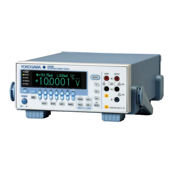
Page 15: Front Panel
Illuminates when there are errors in the error log → Section 14.2 Remote indicator Illuminates when the GS200 is in remote mode (controlled through communications) → Section 12.1 Store indicator Illuminates when store mode is turned on → Section 7.8 Repeat indicator Illuminates when the program’s repeat mode is turned on →... -
Page 16: Rear Panel
Used to connect multiple GS200s and perform synchronous operation. → Section 8.2 USB port Used to connect the GS200 to a PC that has a USB interface and to access the GS200 as USB storage or to control the GS200 through USB-TMC commands. -
Page 17: Display Mode And Displayed Contents
Display Mode and Displayed Contents Display Mode Main Screen Limiter indicators H: High limiter Measurement sample L: Low limiter indicator Measured value Limit Program execution status Source range Source level 1 This is displayed on models with the monitoring (/MON) option. Menu Screen Source level Menu items... - Page 18 In voltage source mode’s 10 mV and 100 mV ranges, the output resistance is approximately 2 Ω . Therefore, these ranges are not suitable when the GS200 is connected to a load that allows current to flow (a low-impedance load). Connect a load that allows as little current to flow as possible (a high-impedance load).
-
Page 19: Keys
ENTER Key (Section 4.1) When the GS200 is in keypad mode, press this key to enter the setting that you have specified. ESC (LOCAL) Key (Section 4.1) When a menu is displayed, press this key to display the previous menu (to move up one level in the menu hierarchy). - Page 20 V Key (Sections 5.2 and 5.3) If you press this key when the GS200 is in up/down key mode and is displaying the main screen, the source function is set to voltage, and the source range is set to 1 V. If you...
- Page 21 1.4 Keys Program Keys PROGRAM Key (Chapter 6) Press this key to display the program menu. If you press this key while you are editing a program, program editing finishes. RUN Key (Section 6.7) Press this key to execute the program from its first step. STEP Key (Section 6.7) Press this key to execute just one of the program’s steps.
-
Page 22: System Configuration
16 MB volatile storage disk (GS200RAM) for storing data such as measurement results. If you use USB to connect the GS200 to a PC, you can access these storage disks as the PC’s external drives. Because settings and results are saved to general text files or .CSV files, you can use software such as a text editor... - Page 23 2.1 System Configuration System Configuration Diagram Use the USB storage Communication feature to connect the Command line GS200 to a PC as the control PC’s external disk. TRIG GS200 OUTPUT TRIG GS200 GS200 READY OUTPUT BNC IN BNC OUT Internal storage...
-
Page 24: Source Feature And Measurement Feature (Monitoring Feature; /Mon Option)
5½ digits. Voltage Source The GS200 has 10 mV, 100 mV, 1 V, 10 V, and 30 V ranges. You can specify and generate a positive or negative voltage of up to 32 V. - Page 25 2.2 Source Feature and Measurement Feature (Monitoring feature; /MON option) Source and Sink Operations The GS200 can perform four-quadrant operation by operating as a current source or a current sink in the range of ±32 V and ±200 mA. During sink operation, the GS200 operates in the same quadrants as it does during source operation, so you can use it not just as a true constant voltage source but also as a highly accurate electronic load.
- Page 26 You can use the program feature to specify up to 10000 output steps. You can edit programs from the GS200 or create program files in CSV format on a PC and use the USB storage feature to load the files on the GS200.
-
Page 27: Source
1 mV ±200 mA * In voltage source mode’s 10 mV and 100 mV ranges, because the GS200 uses a voltage divider, the output resistance is approximately 2 Ω. Therefore, these ranges are not suitable when the GS200 is connected to a load that allows current to flow (a low-impedance load). -
Page 28: Source Function
2.3 Source Current Source Range (See section 5.2 for the procedure) The following current source ranges are available. 200 mA/30 V range 100 mA/30 V range 10 mA/30 V range 1 mA/30 V range Range Source Range Resolution Max. Load Current 1 mA ±1.20000 mA 10 nA... -
Page 29: Output On/Off
The output is connected, and the specified source level is generated. In this mode, program and measurement functions are enabled. Note A mechanical relay operates when the GS200 switches between output on and output off. Note the following points when using the GS200. •... -
Page 30: Local Sense And Remote Sense
(L) is displayed. Tripping the Output If the GS200’s output exceeds the high limiter or falls below the low limiter, the output is automatically turned off. If this occurs, the error indicator illuminates, and the event is written to the error log. -
Page 31: Guard Terminal Feature
Guard Terminal Feature (See section 4.3 for the procedure) If the GS200 and the DUT are far apart or if the GS200 shares its power source with electric motors, common mode noise may be superimposed on the power source signal supplied to the DUT. -
Page 32: Programs
Ti: Program interval time Program Slope Time (See section 6.3 for the procedure) The program slope time specifies the amount of time that the GS200 takes to linearly change (increase or decrease) the current step’s source level to the next step’s source level from the beginning of the step. -
Page 33: Repeating Programs
2.4 Programs Ts = 0 Ts < Ti RUN key RUN key TrigBusy Ready Ts = Ti Ts > Ti RUN key RUN key TrigBusy Ready Ts: Program slope time Ti: Program interval time The TrigBusy signal’s state transitions shown here assume that the program trigger is set to Norm. -
Page 34: Program Files
Comments You can include comments in program files. A comment consists of any text between “//” and a line-feed code or the end of the file. The GS200 ignores comments when it loads program files. Index 2-13... -
Page 35: Executing Programs
When you press the HOLD key to pause program execution, the paused step is said to be in the “mid-execution” state. If you press the STEP key while the GS200 is in this state, the current step that was in the mid-execution state is re-executed. When this step completes, the GS200 pauses the program again. - Page 36 2.4 Programs • If the HOLD Key Is Pressed The GS200 generates 4 V for the remaining 0.5 seconds as specified by the step that was in the mid-execution state, generates 5 V for 1 second, and then continues executing the rest of the program.
-
Page 37: Measurement (Monitoring Feature; /Mon Option)
±210.00 mA Measurement ON/OFF (See section 7.1 for the procedure) Measurement OFF (Off) Measurement is not performed. Select this mode if you only intend to use the GS200 source features. Measurement ON (On) Measurement is performed. The measured value is displayed in the upper-left section of the screen. - Page 38 The zero point may change due to the passage of time, the GS200 being in an environment where the temperature changes drastically, or due to other factors. By executing zero calibration, the zero point is calibrated, and this enables the GS200 to generate more accurate output.
-
Page 39: Store/Recall (Statistical Computation Value Display)
2.5 Measurement (Monitoring feature; /MON option) Store/Recall (Statistical Computation Value Display) Storing Measured Results (See section 7.8 for the procedure) This feature enables you to save the specified number of measured results to storage memory. You can specify a storage count in the range of 1 to 10000. If the storage operation is aborted before the specified storage count is met, the measured results up to that point are stored. - Page 40 2.5 Measurement (Monitoring feature; /MON option) GS200RAM Containing Result Files Third newest result file Second newest result file Newest result file Result File Numbering Past When the first storage Newest result file operation completes Result.csv The file names are automatically updated.
-
Page 41: Triggering
Triggering Overview The GS200 uses program triggers, which are used to start and pause programs, and measurement triggers, which are used to start measurements. Program Triggers (See section 6.4 for the procedure) This trigger is used to drive programs (see section 2.4). On models with the monitoring (/MON) option, you can select the normal (Norm) or measurement end (M.End) trigger... -
Page 42: App
2.6 Triggering Measurement Triggers (/MON option; see section 7.4 for the procedure) This trigger is used to start a measurement operation (see section 2.5). Select any of the following trigger sources. • Measurement timer (Timer) You can set the constant period timer to a period from 0.1 seconds to 3600.0 seconds. The timer is reset when you turn the output on. -
Page 43: Trigger Block Diagram
2.6 Triggering Trigger Block Diagram TrigIn TrigOut “*TRG” Meas.Timer STEP P.Interval Timer HOLD ProgramTrig PROGRAM TrigBusy Ready Meas Trig MEASURE Meas Busy 2-22 IM GS210-01EN... - Page 44 2.6 Triggering Trigger Output (See sections 8.1 and 8.2 for the procedures) The GS200 can output the program trigger signal from the SYNC OUT terminal (I/O terminals for synchronous operation) or the BNC output terminal to the subsequent GS200s that are connected.
-
Page 45: Synchronization
External I/O There are two types of external I/O terminals on the GS200: the I/O terminals for synchronous operation (SYNC In/OUT) and the BNC I/O terminals (IN and OUT). RJ-11 Connector (I/O terminals for synchronous operation; SYNC IN/OUT;... -
Page 46: Other Features
The GS200’s internal memory consists of a 4 MB non-volatile disk (GS200ROM) and a 16 MB volatile disk (GS200RAM). If you use a USB cable to connect the GS200 to a PC, you can access these disks from the PC as removable disks. You can store the... -
Page 47: Usb Communication (Usb-Tmc Command Control)
This folder contains all the panel setup files. Any of the files in this folder can be selected as a setup file. When the GS200 is sent from the factory, a sample setup file is stored in this folder. This sample setup file is also created when you format the disk. -
Page 48: Ethernet Communications (/C10 Option)
The GS200 has an interface that is used to control the GS200 using commands. You can specify the same settings as you would using the front panel keys of the GS200 and output setup data and measured data. Because the command control of the GS200 is mutually independent, other communication features can be used while you are using GP-IB to control the GS200. -
Page 49: Handling Precautions
Handling Precautions Read the Safety Precautions Safety Precautions If you are using the GS200 for the first time, make sure to read “Safety Precautions,” on pages v and vi. Do Not Remove the Case Do not remove the case from the instrument. Some sections inside the instrument have high voltages that are extremely dangerous. -
Page 50: General Handling Precautions
3.1 Handling Precautions General Handling Precautions Do Not Place Objects on Top of the Instrument Never place objects such as those that contain water on top of the instrument. Doing so may damage the instrument. Do Not Apply Shock or Vibration Do not apply shock or vibration. -
Page 51: Installation
Handle Stop Positions (We recommend that you use positions 1, 3, 5, and 8. Do not place a heavy load on the GS200 when the handle is in stop position 2 or 4.) Rotary axis... -
Page 52: Installation Location
No condensation should be present. Note Condensation may form when moving the GS200 from a low temperature or humidity environment to a high temperature or humidity environment, or when there is a sudden change in temperature. In these kinds of circumstances, wait for at least an hour before using the GS200, to acclimate it to the surrounding environment. - Page 53 5°C and 40°C and the relative humidity is between 20% RH and 80% RH. Rack Mount To mount the instrument in a rack, use the separately sold rack mount kit. For the procedure to rack mount the GS200, see the instructions that are included with the rack mount kit. Name...
-
Page 54: Connecting The Power Supply
Approx. 80 VA * The supply voltage that the GS200 can use differs depending on its suffix code. Before you use the instrument, check that the voltage supplied to it is less than or equal to the maximum rated voltage of the power cord provided with it (see page iii for the maximum voltage rating). -
Page 55: Turning The Power Switch On And Off
Operations Performed When the Power Is Turned On When the power switch is turned on, the GS200 logo appears on the screen, and a self- test starts automatically. If the test completes successfully, the GS200 is configured according to the setup file selected in section 9.3, “Selecting the Settings Applied at... -
Page 56: Wiring Precautions
Wiring Precautions WARNING • Be sure to turn the GS200 output off before you connect the device that you are generating output for. • Do not connect a voltage source in voltage source mode or a current source in current source mode. An incorrect connection may damage the GS200. -
Page 57: Wiring The Gs211 Rear Panel Terminal Plug
Wiring the GS211 Rear Panel Terminal Plug Follow the procedure below to wire the rear panel terminal plug on a GS211, which has rear panel output terminals. To prevent electric shock and damage to the instrument, follow the warnings given in section 3.5, “Wiring Precautions.” Unscrew the screws on the left and right of the terminal plug, and remove the terminal plug from the GS211. -
Page 58: Setting The Date, Time, And The Time Difference From Gmt (Greenwich Mean Time)
Setting the Date, Time, and the Time Difference from GMT (Greenwich Mean Time) Procedure Press UTILITY to display the following menu. Press the Sys Config soft key to display the following menu. Press the Adjust Time soft key. Setting the Date and Time Press the Clock soft key to display the date/time setup screen. - Page 59 • Check the date and time setting on your PC. • Check the website at the following URL:http://www.worldtimeserver.com/ Note The GS200 does not support Daylight Saving Time. To set the time to Daylight Saving Time, reset the time difference from Greenwich Mean Time. <<Corresponding Command Mnemonic>>...
-
Page 60: Chapter 4 Common Settings
Press a setting key such as UTILITY or MEASURE to display a soft key menu at the bottom of the screen. Soft Keys Press a soft key to make a choice on the soft key menu or to execute an operation. GS200 DC VOLTAGE/CURRENT SOURCE SENSE OUTPUT... - Page 61 4.1 Basic Key Operations and How to Enter Values In keypad mode, the value that you are entering blinks. Example: Entering “4.5” This part of the display blinks. Press ENTER to enter the value that you have specified. How to Operate Setup Menus Press a key to display a corresponding setup menu.
-
Page 62: Selecting The Wiring System (Remote Sense Or Local Sense)
SENSE terminals are used, the GS200 will be prohibited from generating the correct output, and it may be damaged. When the GS200 is measuring voltage in current source mode and the current becomes large, the voltage drop in the lead wire can no longer be ignored. In such a case, you can measure the voltage with reduced effects of the lead wire resistance by selecting the four-terminal connection (4W) and connecting the SENSE terminals near the DUT. - Page 63 2 for these voltage ranges, they are not suitable when the GS200 is connected to a load that allows current to flow (a low-impedance load). Connect a high-impedance load, a load that is sufficiently larger than the output resistance.
-
Page 64: Setting The Guard Terminal
Setting the Guard Terminal Procedure Press UTILITY to display the following menu. Press the Guard soft key to select On or Off. Index IM GS210-01EN... -
Page 65: Chapter 5 Source
(b). When the GS200 is not connected to the DUT, as shown in figure (c), you can reduce the effect of common mode noise by turning the guard feature off and directly connecting the DUT’s ground (noise source) to the guard terminal. - Page 66 Press the Storag soft key. Connection Cable Use a USB cable that has a type B connector (receptacle). How to Connect the USB Cable Connect a USB cable to the USB port on the GS200 rear panel. USB port LINK ETHERNET...
- Page 67 Press the Yes soft key to format the disk. Note • Always format the disk from the GS200 menu. If you format the disk from your PC, folders such as PROGRAM and the sample files are not created. • You can create files and folders on the disk, but be sure that it does not become full.
- Page 68 The PROGRAM folder stores program files that you can select when you want to execute a program. When the GS200 is sent from the factory or when the disk is formatted, two sample program files are stored in this folder.
-
Page 69: Setting The Source Function
Chapter 5 Source Setting the Source Function Procedure Press V, mV, or mA. Explanation For details on the source function, see section 2.3. Display Example of Source Function Voltage source (mV) The relationship between the keys and the source function is as follows: •... -
Page 70: Setting The Source Range
• In voltage source mode’s 10 mV and 100 mV ranges, because the GS200 uses a voltage Ω divider, the output resistance is approximately 2 . -
Page 71: Setting The Source Level
ENTER The source function and source range do not change. Note Because an output capacitance of approximately 500 pF exists between the GS200’s OUTPUT Hi and OUTPUT Lo terminals: • If the load changes drastically such as when a short circuit occurs in voltage source mode, a large transient discharge current is generated from the output capacitance. -
Page 72: Setting The Limiter
Setting the Limiter Procedure Press LIMIT to display the limiter setup screen. Example of setting the current limiter in voltage source mode In up/down key mode, press the keys to set the limit. In keypad mode, press NUM LOCK + to set the limit. -
Page 73: Turning The Output On And Off
The Relationship between Capacitive and Inductive Loads and Output • When a capacitive load is connected to the GS200 in voltage source mode, the response time may become longer. Also, if the load has a capacitance of 10 μF or greater, oscillation may occur. -
Page 74: Chapter 6 Programs
Explanation Program Repetition Mode If you set Repeat to On, when the final step in the program completes, the GS200 will return to the first step in the program and repeat it. You cannot set the number of times that the program is repeated. -
Page 75: Setting The Program Interval Time
Setting the Program Interval Time Procedure Press PROGRAM to display the following menu. Press the Intvl soft key to display the program interval time setup screen. In up/down key mode, press the keys to set the program interval time. In keypad mode, press NUM LOCK + to set the program interval time. -
Page 76: Setting The Program Slope Time
When a program slope time is specified, the source level does not change immediately at the start of the step. The program slope time is the time that the GS200 takes to change the source level gradually (ramp up or down) from the start of a step. For details on the program slope time, see section 2.4. -
Page 77: Setting The Program Trigger (/Mon Option)
Setting the Program Trigger (/MON option) Procedure Press PROGRAM to display the following menu. Press the P.Trig soft key to display the following menu. Press the Norm or M.End soft key to set the program trigger. Explanation On models with the /MON option, you can select Norm or M.End for the program trigger. On models without the /MON option, the program trigger is fixed to Norm, and this menu is not displayed. -
Page 78: Creating And Editing Programs
Creating and Editing Programs Procedure Creating and Editing Programs from the GS200 Press PROGRAM to display the following menu. Press the Edit Memory soft key to display the program editing screen. Displayed when this is a new step Number of the step that is... - Page 79 Note When the GS200 turns off, the program that you have edited is lost. If you want to keep the program, save it before you turn the GS200 off (see section 6.6). Creating and Editing Programs from a PC You can use a spreadsheet application or text editor to create and edit program files from a PC.
- Page 80 When you create a new program, the initial source level value is 0 V or 0 mA. Editing Programs When you create a program on the GS200, the program is displayed on the screen. When you load an existing program onto the GS200, the program is displayed on the screen.
-
Page 81: Saving And Loading Programs
Saving and Loading Programs Procedure Press PROGRAM to display the following menu. Press the List Files soft key to display the currently saved files and the following menu. Saving Programs Press the Save File soft key to display the following menu. Using a Soft Key to Directly Specify the Program from Pgrm01 to Pgrm04 Press a soft key from Pgrm01 to Pgrm04 to save the corresponding program. - Page 82 Loading Files That Were Created on a PC onto the GS200 Follow the procedures listed in section 4.4, “Setting the USB Storage Feature” and “How to Connect the USB Cable” to connect the GS200 and a PC using a USB cable.
- Page 83 Loading Programs You can load a saved program file to restore the program. Note If the GS200 cannot read program files correctly, its CSV-format settings may not match the program files. Check the CSV-format settings (see section 9.5). 6-10 IM GS210-01EN...
- Page 84 6.6 Saving and Loading Programs Deleting Programs You can delete program files that you no longer need. Displaying Program Contents You can check the contents of program files. <<Corresponding Command Mnemonic>> :PROGram:SAVE <character string> :PROGram:LOAD <character string> :PROGram:DELete <character string> :PROGram:CATalog? :PROGram:MEMory <character string>...
-
Page 85: Executing Programs
Press OUTPUT or apply an output control signal (output on) to turn output on. Program execution starts as soon as the measurement operation completes. Explanation The GS200’s Screen during Program Execution Number of the step that is currently running Remaining program... - Page 86 The RUN, STEP, and HOLD keys and external triggers are disabled. Additionally, the program interval setting is ignored. Note If you use a PC to copy or delete files on the GS200 during program execution, the timing of the program operations may be affected. <<Corresponding Command Mnemonic>>...
-
Page 87: Turning Measurement On And Off
Measurement on) On ( When the source function is set to voltage, the GS200 measures current. When the source function is set to current, the GS200 measures voltage. The GS200 performs measurement when output is on. The measured value is displayed in the upper-left section of the screen. -
Page 88: Setting The Integration Time
Set the integration time to an integer multiple of the power line cycle (nPLC). The line frequency is measured automatically inside the GS200. You can use the communication command “ :SYSTem:LFRequency? ” to check the measured line frequency. -
Page 89: Setting The Measurement Delay
Explanation Measurement Delay The measurement delay is the time that the GS200 waits from when the measurement trigger is generated until measurement actually starts. Set this delay if you want to insert a delay after the source level is changed until the measurement is actually started to allow the DUT to stabilize. -
Page 90: Selecting The Measurement Trigger
Selecting the Measurement Trigger Procedure Press MEASURE to display the following menu. Press the Meas Config soft key to display the following menu. Press the soft key that corresponds to the measurement trigger that you want to use. Explanation For details on measurement triggers, see section 2.6. The measurement trigger is a signal source that is used to start measurement. -
Page 91: Setting The Measurement Timer
Setting the Measurement Timer Procedure Press MEASURE to display the following menu. Press the Meas Config soft key to display the following menu. Press the Timer soft key to display the measurement timer setup screen. In up/down key mode, press the keys to set the measurement timer. -
Page 92: Turning The Null Computation On And Off
Turning the NULL Computation On and Off Procedure Press MEASURE to display the following menu. Press the Null soft key to select On or Off. Explanation NULL Computation When you turn NULL computation on, the NULL value will be set to the next measured value. -
Page 93: Zero Calibration (Zero Reference Measurement)
The zero point may change due to the passage of time, the GS200 being in an environment where the temperature changes drastically, or due to other factors. By executing zero calibration, the zero point is calibrated, and this enables the GS200 to generate more accurate output measurement. -
Page 94: Storing Measured Results
Storing Measured Results Procedure Press MEASURE to display the following menu. Press the Store Config soft key to display the following menu. Setting the Storage Count Press the Count soft key to display the storage count setup screen. In up/down key mode, press the keys to set the storage count. - Page 95 GS200RAM is a volatile-memory disk. The files that are stored on it are lost when you turn off the GS200. If there are result files that you want to retain, move them to the connected PC before you turn off the GS200.
-
Page 96: Performing Statistical Computations On Measured Values (Recall)
Performing Statistical Computations on Measured Values (Recall) Procedure Press MEASURE to display the following menu. Press the Store Config soft key to display the following menu. Press the Recall soft key to display statistical computations of the measured values that were most recently stored. Explanation For details on the statistical computation feature, see section 2.5. -
Page 97: Chapter 8 Synchronous Operation
Set the BNC IN terminal’s signal by selecting Trig or Output on the BNC In menu. Explanation For details on the BNC I/O terminals, see section 2.7. The GS200 can transmit or receive the following signals through the BNC I/O terminals on the rear panel. • Output terminal (OUT) Trig: The TrigBusy signal (see section 2.4) - Page 98 This pin receives output control signals. When these signals are received, the GS200 performs the same operation as if its OUTPUT key had been pressed. When a falling edge is received, the GS200 turns output on. When a rising edge is received, the GS200 turns output off.
- Page 99 Using the BNC Terminals to Perform Synchronous Operation with the GS200 and Other Devices You can control the GS200’s output (turning on and off) and program execution by applying OUTPUT IN or TRIG IN signals that are transmitted from a device such as a controller.
-
Page 100: Using The Rj-11 Connectors (Sync In And Sync Out) To Perform Synchronous Operation
Use a synchronous operation cable (sold separately; 758960; 6-wire) to connect two GS200s. You can make synchronous operation possible by connecting the synchronous operation output of a higher level GS200 to the synchronous operation input of a lower level GS200. -
Page 101: The Maximum Delay From Trig In To Trig Out Is Less Than Or Equal To 1
This pin receives output control signals. When these signals are received, the GS200 performs the same operation as if its OUTPUT key had been pressed. When a falling edge is received, the GS200 turns output on. When a rising edge is received, the GS200 turns output off. -
Page 102: Chapter 9 Other Features
While the setup data is being initialized, the soft key is highlighted. Explanation When you initialize the setup data, the GS200 is returned to its factory default settings. For information on the factory default settings, see appendix 1, “Factory Default Settings.” <<Corresponding Command Mnemonic>>... -
Page 103: Saving, Loading, And Deleting Setup Data
Saving, Loading, and Deleting Setup Data Procedure Press SETUP to display the currently saved files and the following menu. Saving Setup Data Press the Save Setup soft key to display soft keys that represent the files that you can save to (Setup01 to Setup04). Saving the File by Pressing its Corresponding Soft Key Press a soft key from Setup01 to Setup04 to save the corresponding file. - Page 104 9.2 Saving, Loading, and Deleting Setup Data Deleting Setup Data Press the soft key to move the cursor (underline) up and down and select the setup file that you want to delete. Press the Delete Setup soft key to display the following menu. To delete the setup file, press the Yes soft key.
-
Page 105: Selecting The Settings Applied At Power-On
Press SETUP to display the following menu. Press the soft key to move the cursor (underline) up and down and select the setup file that you want to load the settings from when the GS200 turns on. Press the Set to PwrOn soft key. - Page 106 Turning the display off extends the life of the display and suppresses the noise that the display generates. Turning the Beep Sound On and Off If you turn the beep sound on, the GS200 generates beep sounds during operation, such as when an error occurs. <<Corresponding Command Mnemonic>>...
-
Page 107: Selecting The Csv File Format
Selecting the CSV File Format Procedure Press UTILITY to display the following menu. Press the Sys Config soft key to display the following menu. Press the CSV Formt soft key to display the following menu. Press the Point or Sep soft key to select the CSV file format. The two soft keys are linked. - Page 108 The error memory is also cleared if you use a communication command (“ :SYSTem: • ERRor? ”) to read errors, or if the GS200 is turned off. You can also clear the error memory by sending the *CLS communication command.
-
Page 109: Chapter 10 Usb Interface
PC (see section 4.4, “USB Storage Feature”). USB-TMC Command Control Feature You can control the GS200 by using commands from a VISA (Virtual Instrument Software Architecture) library. To perform USB-TMC command control, you must first install a VISA library on your PC. -
Page 110: Setting The Usb Interface Mode
10.2 Setting the USB Interface Mode Procedure Press UTILITY to display the following menu. Press the Remot I/F soft key to display the following menu. Setting the USB Interface Mode Press the USB soft key to display the following menu. Press the soft key that corresponds to the USB interface mode that you want to use. - Page 111 10.3 Viewing the VISA Setup Information Procedure Press UTILITY to display the following menu. Press the Remot I/F soft key to display the following menu. Viewing the VISA Information Press the VISA Info soft key to display the network setup information that is necessary for communications using a VISA library.
-
Page 112: Chapter 11 Ethernet Interface (Option)
21. HTTP Server Feature The HTTP server feature (connected to on port 80) enables you to use a Web browser to display various GS200 information and control the GS200 remotely. Ethernet Interface Specifications Connector: RJ-45... -
Page 113: Connecting To A Network
(straight cable) Note • Use straight UTP or STP cables that are category 5 or better. • Do not connect the GS200 to a PC directly. Direct communication without a hub or router is not guaranteed to work. 11-2 IM GS210-01EN... -
Page 114: Configuring Network Settings (Tcp/Ip)
You can only set the IP address when DHCP is off. Press the IP Adrs soft key to display the IP address setup screen. The NUM LOCK key illuminates, and the GS200 changes to keypad mode. Press the keys that correspond to numbers 0 to 9 and the period to set the IP address. - Page 115 • Different information may be assigned to the GS200 each time it is turned on. When you are using a PC to access the GS200, you must check the GS200 IP address and other network settings each time you turn the GS200 on.
- Page 116 You can set the terminator that is used to send data from the command control server at port 7655. • Select CR, LF, or CR+LF. • The GS200 handles CR, LF, or CR+LF as the terminator when receiving data. Note •...
-
Page 117: Viewing The Network Settings
If DHCP is enabled, “0.0.0.0” will be displayed for the IP address, subnet mask, and default gateway until an address is assigned to the GS200. If the display does not change even after 30 seconds elapses after the GS200 is turned on, the DHCP address assignment may have failed. -
Page 118: Web Server Feature
11.5 Web Server Feature The GS200 Web server feature links the Web browser on your PC to the GS200 and enables you to control the GS200 from your Web browser window. The GS200 Web server provides you with the following features. - Page 119 Type the IP address of the GS200 in the Address box, and press ENTER. IP address example: http://10.0.159.30/ If a connection to the GS200 Web server is established, the top page of the GS200 Web Service is displayed. Web Server Window...
- Page 120 Click to update the remote panel to reflect the operations carried out on the GS200 You can control the GS200 in the same manner as if you were using the actual keys on the GS200. Use your mouse to click the keys that you want to operate. Operations that you perform on the remote panel are immediately applied to the GS200.
- Page 121 Displaying the Communication Environment Click the “Status” link in the Web server window to display the communication environment page. The communication environment of the GS200 is displayed. Click Refresh to update the displayed information. 11-10 IM GS210-01EN...
- Page 122 Click the “FTP” link in the Web server window to display the FTP page. The GS200 volatile disk (GS200RAM) and non-volatile disk (GS200ROM) are displayed. You can view, duplicate, delete, or transfer these files to your PC from the FTP page. For details on the volatile disk (GS200RAM) and non-volatile disk (GS200ROM), see “USB...
-
Page 123: Chapter 12 Gp-Ib Interface
Listener Capability • You can use the GP-IB interface to specify the same settings that you can using the front panel keys. You cannot use it to turn the GS200 on and off or change communication settings. • The GP-IB interface receives output requests for setup data and measured data from the controller. -
Page 124: Connecting The Gp-Ib Cable
12.2 Connecting the GP-IB Cable GP-IB Cable The GS200 is equipped with an IEEE St’d 488-1987 24-pin GP-IB connector. Use a GP- IB cable that conforms to this standard. Connection Procedure Connect the cable as shown below. GP-IB connector GP-IB cable Precautions to Be Taken When Connecting the Cable •... -
Page 125: Setting The Gp-Ib Address And Command Mode
Each device that is connected by GP-IB has its own unique address in the GP-IB system. This address is used to distinguish between different devices. When you connect the GS200 to a controller such as a PC, specify the GS200’s GP-IB address on the controller. -
Page 126: 7651-Compatible Mode
If you press the ENTER key when the GP-IB command mode is set to 7651, the status byte’s SRQ SW bit is set to 1. The GS200 issues an SRQ interruption if it is set to use the SRQ SW bit as an interruption source. For details, see the 7651 User’s Manual, IM7651-01E. - Page 127 12.5 Responses to Interface Messages What Are Interface Messages? Interface messages are also referred to as interface commands or bus commands. They are commands that are issued by the controller. They are classified as follows: Uni-line Messages A single control line is used to transmit uni-line messages. The following three types of messages are available.
- Page 128 Clears the serial polling mode of the talker function on all devices on the bus. • PPU Not supported. Interface messages Multi-line messages Uni-line Address Universal messages commands commands IFC* LLO* GTL* REN* DCL* SDC* SPE* GET* SPD* Listener Talker Secondary address address commands * Interface message that the GS200 supports 12-6 IM GS210-01EN...
- Page 129 Device settings at power-up. The commands that can be used at power-up. The settings selected in section 9.3, “Selecting the Settings Applied at Power-On.” If you issue the RST common command, the GS200 always returns to the factory default settings.
- Page 130 12.6 About the IEEE 488.2-1992 Standard (11) Size of the response data block 2 MB maximum. (12) A list of supported common commands See section 13.2.11, “Common Commands.” (13) Device condition after a successful calibration The settings return to the conditions that existed before the calibration, measurements are terminated, and previous measured data are invalidated.
-
Page 131: Chapter 13 Communication Commands
The GS200 returns a single response message in response to a single program message. Program Messages Data that is sent from the controller to the GS200 is called a program message. The program message format is shown below. <Program message unit>... - Page 132 <PMT> Response Messages <PMT> is a program message terminator. The following Data that is sent from the GS200 to the controller is three types of program terminators are available. called a response message. The response message • NL (New line) syntax is shown below.
-
Page 133: Commands
Deadlock The GS200 can store at least 64 KB of messages in its <Mnemonic> transmit and receive buffers (the number of available bytes varies depending on the operating conditions). -
Page 134: Source Change
FUNCtio RANGe 100E-3<PMT> :SOURce:LEVel:FIX :SOURce:LEVel:AUTO Header Interpretation Rules :SOURce:PROTection:VOLTage The GS200 interprets the header that it receives :SOURce:PROTection:CURRent according to the rules below. • Mnemonics are not case sensitive. When Concatenating Commands of the Same SOURce can also be written as... -
Page 135: Responses
In a <floating-point number>, the + sign after E can be omitted. <Block Data> <Block data> is any 8-bit data. It is only used in response messages on the GS200. The syntax is as follows: Syntax Example #N<N-digit decimal number><data byte sequence>... - Page 136 13.1 Program Format <Multiplier> The table below lists the <multipliers> that can be added after a <value>. Symbol Word Multiplier Yotta Zetta Peta Tera Giga Mega Kilo – 3 Milli – 6 Micro – 9 Nano – 12 Pico – 15 Femto –...
-
Page 137: Commands
13.2 Commands 13.2.1 List of Commands Command Function Page Output Commands (OUTPut group) :OUTPut [:STATe]/? Sets or queries the output state (on/off). 13-10 Source Commands (SOURce group) :SOURce :FUNCtion/? Sets or queries the source function (voltage/current). 13-11 :RANGe/? Sets or queries the source range. 13-11 :LEVel [:FIX]/? - Page 138 13-17 :FETCh? Queries the measured result. 13-17 :READ? Clears the measured value, prepares the GS200 to perform the next measurement, and queries the measured result. 13-17 :MEASure? Clears the measured value, prepares the GS200 to perform the next measurement, generates a measurement trigger, and queries the measured result.
- Page 139 13.2 Commands Command Function Page Status Commands (STATus group) :STATus :CONDition? Queries the condition register. 13-23 :EVENt? Queries and clears the extended event register. 13-23 :ENABle/? Sets or queries the extended event enable register. 13-23 :ERRor? Queries and clears the most recent error information. 13-23 Common Commands *CLS...
-
Page 140: Output Commands (Output Group)
13.2 Commands 13.2.2 Output Commands (OUTPut group) :OUTPut[:STATe]/? Function Sets or queries the output state (on/off). Syntax :OUTPut[:STATe] 1|0|ON|OFF 1 or ON Turns the output on. 0 or OFF Turns the output off. :OUTPut[:STATe]? → 1 The output is on. → 0 The output is off. -
Page 141: Source Commands (Source Group)
13.2 Commands 13.2.3 Source Commands (SOURce group) :SOURce:FUNCtion/? → 1E+0 The range that is being used is 1 V. Function Sets or queries the source function (voltage/ → 10E+0 The range that is being current). used is 10 V. Syntax :SOURce:FUNCtion VOLTage|CURRent → 30E+0 T he range that is being... - Page 142 13.2 Commands :SOURce:LEVel:AUTO/? :SOURce:PROTection:VOLTage/? Function Sets or queries the source level in terms of the Function Sets or queries the voltage limiter level. most appropriate range. Syntax :SOURce:PROTection:VOLTage <voltage>| Syntax :SOURce:LEVel:AUTO <voltage>|<current>| MINimum|MAXimum <voltage> Specify a voltage limiter MINimum|MAXimum <voltage> Specify a voltage level. level.
- Page 143 13.2 Commands 13.2.4 Program Commands (PROGram group) :PROGram:TRIGger/? :PROGram:REPeat[:STATe]/? Function Sets or queries the program trigger. Function Sets or queries the program execution repetition Syntax :PROGram:TRIGger NORMal|MEND mode (on/off). NORMal Sets the trigger normal. Syntax :PROGram:REPeat[:STATe] 1|0|ON|OFF MEND Sets the trigger to 1 or ON Turns repetition mode on.
- Page 144 13.2 Commands :PROGram:DELete :PROGram:HOLD Function Deletes a program file. Function Pauses and resumes program execution. Syntax :PROGram:DELete <character string> Syntax :PROGram:HOLD <character string> The name of the program Example :PROG:HOLD file that you want to delete. Description If a program is running, this command pauses Example the program execution.
-
Page 145: Measurement Commands (Sense Group)
13.2 Commands 13.2.5 Measurement Commands (SENSe group) :SENSe[:STATe]/? Example :SENS:DEL 0.5 :SENS:DEL? Function Sets or queries the measurement feature (on/off). Description This command is only valid on models with the Syntax :SENSe[:STATe] 1|0|ON|OFF /MON option. 1 or ON Turns the measurement feature on. :SENSe:TRIGger/? 0 or OFF Turns the measurement... - Page 146 13.2 Commands :SENSe:NULL[:STATe]/? Function Sets or queries the NULL computation feature (on/off). Syntax :SENSe:NULL[:STATe] 1|0|ON|OFF 1 or ON Turns the NULL computation feature on. 0 or OFF Turns the NULL computation feature off. :SENSe:NULL[:STATe]? → 1 The NULL computation feature is on. →...
- Page 147 → <real number> The measured result. Example :READ? Description This command is the same as :INIT;:FETC?. If this command is received when the GS200 is not performing measurements, no result is returned. :MEASure? Function Clears the measured value, prepares the GS200...
- Page 148 13.2 Commands 13.2.7 Store/Recall Commands (TRACe group) The commands in this group are only valid on models with the /MON option. :TRACe[:STATe]/? :TRACe:ACTual? Function Sets or queries the storage state (on/off). Function Queries the number of stored results. Syntax :TRACe[:STATe] 1|0|ON|OFF Syntax :TRACe:ACTual? 1 or ON...
- Page 149 13.2 Commands :TRACe:DATA:READ? [TM|SF|SL|MF|ML] <source level n> is Function Loads stored data. an IEEE754 double-precision, 8-byte Syntax floating-point number :TRACe:DATA:READ? [TM|SF|SL|MF|ML] Loads a timestamp. <measured value n> is Loads the source function. an IEEE754 double-precision, 8-byte Loads the source level. floating-point number Loads the measurement •...
-
Page 150: External I/O Commands (Route Group)
13.2 Commands 13.2.8 External I/O Commands (ROUTe group) :ROUTe:BNCO/? Function Sets or queries the output BNC signal. Syntax :ROUTe:BNCO TRIGger|OUTPut|READy TRIGger Sets the output BNC signal to the program trigger signal. OUTPut Sets the output BNC signal to the output state signal. READy Sets the output BNC signal to the READY signal. -
Page 151: System Commands (System Group)
13.2 Commands 13.2.9 System Commands (SYSTem group) :SYSTem:SETup:SAVE :SYSTem:DISPlay:BRIGht/? Function Saves setup data. Function Sets or queries the display brightness. Syntax :SYSTem:SETup:SAVE <character string> Syntax :SYSTem:DISPlay:BRIGht <integer>|MINim <character string> The name of the setup data um|MAXimum|UP|DOWN file that you want to save. <integer>... - Page 152 Specify the time difference ERRor?. from GMT as a character :SYSTem:LOCal string in the format “h:m.” h = hours (–12 to 13) Function Switches the GS200 to local mode. m = minutes (0 to 59) Syntax :SYSTem:LOCal? Example :SYSTem:CLOCk:TZONe? :SYST:LOC? →...
-
Page 153: Status Commands (Status Group)
13.2 Commands 13.2.10 Status Commands (STATus group) :STATus:CONDition? Function Queries the condition register. Syntax :STATus:CONDition? → <integer> The current value of the condition register. Example :STAT:COND? :STATus:EVENt? Function Queries and clears the extended event register. Syntax :STATus:EVENt? → <integer> The current value of the extended event register. -
Page 154: Common Commands
13.2 Commands 13.2.11 Common Commands *TRG *CLS Function Generates a measurement trigger. Function Clears the event register, extended event Syntax *TRG register, and error queue. Example *TRG Syntax *CLS Description This command is only valid on models with the Example *CLS /MON option. - Page 155 13.2 Commands *ESE/? Function Sets or queries the standard event enable register. Syntax *ESE <integer> <integer> Specify an integer from 0 to 255. *ESE? → <integer> The current value of the standard event enable register. Example *ESE 6 *ESE? *OPC Function Generates a standard event OPC when all previous commands complete.
-
Page 156: Status Reports
13.3 Status Reports 13.3.1 Status Reports Status Reports The figure below shows the format of status reports that are read by serial polling. This status report format is an extended version of the status report format defined in IEEE 488.2-1992. Standard Event Standard Event Enable Register... -
Page 157: Enable Registers
13.3 Status Reports Overview of Registers and Queues Name Function Write Read Status byte — Serial polling (RQS), *STB? (MSS) Service request enable register Status byte mask *SRE *SRE? Standard event register Indicates device status changes — *ESR? Standard event enable register Standard event register mask *ESE *ESE? - Page 158 5 of the service request enable register Bit 1 EES (Extended Event Summary Bit) is 1, bit 6 (MSS) is set to 1, and the GS200 requests This bit is set to 1 when the logical AND of the service from the controller.
-
Page 159: Standard Event Register
Bit 7 PON (Power On) • When the GS200 is restarted. This bit is set to 1 when the GS200 turns on. Bit Masking To mask a certain bit of the standard event register so that it does not cause bit 5 (ESB) in the status byte to change, set the corresponding bit of the standard event enable register to 0. -
Page 160: Extended Event Register
Bit 0 EOM (End of measure) s high limiter has not activated. The condition register bit is set to 0 when the GS200 is Bit 12 TRP (Tripped) performing measurement and set to 1 when the GS200 The extended event register bit is set to 1 when the is not performing measurement. -
Page 161: Condition Register
(–113) and the error message (“Undefined header”) are stored in the error queue when the GS200 displays the error message. You can use the :SYSTem:ERRor? query to read the contents of the error queue. Like the output queue, the messages in the error queue are read from the oldest one first. -
Page 162: Chapter 14 Troubleshooting And Maintenance
Problem Probable Cause Corrective Action Refer to Section The GS200 does not Using a power supply outside Use a correct power supply. 3.3 turn on. the ratings. The GS200 does not The setup file is corrupt. If the GS200 does not start properly even after you start properly restart it, hold down the ESC and +/– keys while you turn the power on. T he GS200 formats the GS200ROM disk to enable startup. If the GS200 still does not start correctly, servicing is required. Nothing is displayed. The display is turned off. I f the NUM LOCK key is blinking, the display is 9.4 turned off. Press any key. Keys do not work. The GS200 is in remote mode. T he GS200 is in remote mode when the remote — indicator is illuminated. Press the ESC key to switch the GS200 to local mode. Other causes. I f a certain key does not work, it may be due to a 14.3 bad connection. Perform the self test’s key test. If there are keys that you cannot operate, servicing is required. -
Page 163: Troubleshooting
Delete unneeded files or format the disk. the disk. Unable to use the Communication settings on Match the GS200’s communication settings with Chapters communication interface the GS200 and PC do not match. those on the PC. 10 to 12 to set the GS200. 14-2 IM GS210-01EN... -
Page 164: Error Code Descriptions And Corrective Actions
14.2 Error Code Descriptions and Corrective Actions The following two types of messages can appear in the center of the display or the error log view. • Error messages (Error) Error messages are displayed when an inappropriate operation is carried out. •... - Page 165 Device Errors (–300 to –399) Error No. Error Message Corrective Action Page –311 Memory error Restart the GS200. If the error still appears, servicing — is necessary. –320 Storage fault Format the disk. If you cannot format the disk, servicing is necessary.
- Page 166 Program is not being edited You can only end program editing when a program is being edited. Program is being edited You cannot change GS200 settings or run a program when a program is being edited. Illegal file Check that the file is correct.
-
Page 167: Self-Test
14.3 Self-Test Procedure Displaying the Self-Test Menu Press UTILITY to display the following menu. Press the Sys Config soft key to display the following menu. Press the Test soft key. Executing the Display Test Press the Display Test soft key. The entire display and the SAMPLE ERROR indicator illuminate. - Page 168 If the name of the key is not displayed, contact your nearest YOKOGAWA dealer. Self-Test The self-test checks whether the internal functions of the GS200 are operating correctly. If an error appears, contact your nearest YOKOGAWA dealer. Note When any of these tests begins, the output is turned off.
-
Page 169: Viewing The Product Information
14.4 Viewing the Product Information Procedure Press UTILITY to display the following menu. Press the Sys Info soft key. Explanation The following information is displayed. Product name Model Serial number Most recent firmware revision and update date/time Most recent logic revision Calibration date <<Corresponding Command Mnemonic>>... -
Page 170: Updating The System Firmware
“Safe to Remove Hardware” message will appear. • After you press the Update Sys soft key, do not turn the GS200 off until the system file has been completely overwritten. Doing so may damage the instrument. - Page 171 You must store the most recent system file on the GS200RAM before you update the system firmware. You can download the system file from the YOKOGAWA website at the following URL: http://tmi.yokogawa.com/products/generators-sources/ The website listed above also contains information about useful applications for use with the GS200.
-
Page 172: Changing The Power Fuse
GS200. Remove the blown fuse from the fuse holder. Insert a new fuse into the fuse holder, and re-attach the fuse holder to the GS200. Fuse Fuse... -
Page 173: Recommended Replacement Parts And Maintenance
5 years 3 years Source output relay Electrical life: Approximately 100,000 operations Calibration We recommend that you calibrate the GS200 once a year to assure its accuracy. Contact your nearest YOKOGAWA dealer to have your GS200 calibrated. 14-12 IM GS210-01EN... -
Page 174: Chapter 15 Specifications
Chapter 15 Specifications 15.1 Source Section DC Voltage Source Range Range Resolution 24 h Stability 90-Day Stability 90-Day Accuracy 1-Year Accuracy Temperature Generated ±(% of setting ±(% of setting ±(% of setting ±(% of setting Coefficient + μV) + μV) + μV) + μV) ±(% of setting... - Page 175 15.1 Source Section Item Specifications Limiter Limiter Range Resolution Current limiter (only in voltage source mode) 1 mA to 200 mA 1 mA Voltage limiter (only in current source mode) 1 V to 30 V Response time (reference) 10 ms or less for all voltage source and current source ranges. The time for the output to reach within 0.1% of the final value after the output starts changing.
-
Page 176: Measurement Section (On Models With The /Mon Option)
15.2 Measurement Section (On models with the / MON option) DC Voltage Measurement Range Measurement Resolution Input Resistance 1-Year Accuracy (1 PLC) Temperature Coefficient Range ±(% of reading + mV) ±(% of reading + mV)/°C 30 V ±31.000 V 1 mV 10 MΩ... -
Page 177: External I/O Section (Bnc (In/Out) And I/O For Synchronous Operation (Sync In/Out))
I/O level Minimum pulse width 10 μs Pinout Pin No. SYNC IN SYNC OUT OUTPUT IN OUTPUT OUT TRIG IN TRIG OUT READY OUT * This pin is used for servicing the GS200. Do not use it. 15-4 IM GS210-01EN... -
Page 178: Interface
15.5 Interface GP-IB Interface Item Specifications Electrical and mechanical Conforms to IEEE St’d 488-1987 specifications Functional specifications SH1, AH1, T6, L4, SR1, RL1, PP0, DC1, DT1, and C0 Protocol Conforms to IEEE St’d 488.2-1992 Address 0 to 30 USB Interface Item Specifications Number of ports... -
Page 179: General Specifications
15.6 General Specifications Item Specifications 256 × 64 dots fluorescent tube (VFD) Display Internal memory GS200ROM: 4 MB (non-volatile; used to save setup files and program files) GS200RAM: 16 MB (volatile, cleared when the power is turned off; used to save the measured results) Warm-up time Approx. - Page 180 1 Applies to products that have a CE mark on their rear panel. For information on other products, contact your nearest YOKOGAWA dealer. 2 The measurement category of the GS200 signal input terminals is Other (O). Do not use it to measure the main power supply or for Measurement Categories II, III, and IV.
-
Page 181: External Dimensions
15.7 External Dimensions Unit : mm (approx. inch) GS210 GS211 REAR VIEW 252.2 ( 9.93 ) 19.6 19.6 ( 0.77 ) ( 8.39 ) ( 0.77 ) ( 73.3 ) 28.5 ( 13.78 ) ( 2.89 ) ( 1.12 ) ( 18.90 ) ±1 Rack Mount ( JIS ) -
Page 182: Appendix
Subnet mask address 0.0.0.0 Default gateway address 0.0.0.0 Transmission terminator CR+LF Other settings File that is loaded when the Unspecified GS200 turns on Display brightness Display on/off Beep sound on/off Date and time Japan Standard Time Time difference from GMT +9:00... -
Page 183: Appendix 2 Block Diagram
DAC and the various switches that are used for making range settings and other settings. When the GS200 is operating as a voltage source, SW1 is connected to V, and source voltage Vo is the product of source DAC value Vs and R2/R1. If load current IL increases positively and IL ×... - Page 184 GP-IB interface..............12-1 Clear PwrOn ................9-4 GPIB ..................12-3 Clock..................3-10 Greenwich Mean Time............3-11 Comm ................2-21, 7-4 GS200 .................. 12-3 commands, list of..............13-7 GS200RAM ..............2-26, 4-9 Count ..................7-8 GS200ROM ..............2-25, 4-9 CSV Formt ................9-6 Guard..................
- Page 185 Index program repetition mode ............6-1 Page programs ................2-11 LAN................11-3, 11-6 programs, creating..............6-5 LIMIT ................1-6, 5-4 programs, deleting ..............6-9 limit ..................5-4 programs, executing ............. 6-12 limiter ................2-8, 5-4 programs, loading ..............6-9 List Files ................6-8, 6-9 programs, saving ..............
- Page 186 Index system update ..............14-9 Page TCP/IP ...................11-3 Term ..................11-4 terminal plug ................3-9 Test ..................14-6 Timer ..............2-21, 7-4, 7-5 timer ..................7-4 Time Zone ................3-11 transmission terminator ............11-4 TrigBusy ................2-7, 8-5 trigger block diagram ............2-22 trigger busy ................
Need help?
Do you have a question about the GS200 and is the answer not in the manual?
Questions and answers