
Summary of Contents for LUMAT LB 9507
- Page 1 LUMAT LB 9507 Variable Injector Firmware Version 5.03 Id. No.: 81 957 BA4 Rev. No.: 06 5.03.2001...
-
Page 3: Table Of Contents
Structure and Operation of the Software The Principle of Measurement Sample Tubes Data Management and Software update 1-10 Simple and Reliable Operation 1-11 Instrument and software versions 1-11 DESIGN OF LUMAT LB 9507 Keyboard Display Printer Measurement Unit Reagent Storage Area 2-10 Variable injectors 2-11... - Page 4 Contents LB 9507 Introduction Creating Raw Data Protocols Editing/Deleting Protocols Performing Raw Data Measurements 5-11 CUT-OFF MEASUREMENTS Introduction Creating CUT-OFF Protocols Editing/Deleting Protocols 6-12 Running Cut-off Measurements 6-14 QUANTITATIVE MEASUREMENTS (LIA...) Introduction Setting Up Quantitative Protocols Editing/Deleting Protocols 7-12 Entering a Master Curve...
- Page 5 11.4.2 Rerun of a 2-Point Calibrator Protocol 11-14 CONNECTION TO EXTERNAL COMPUTERS 12-1 12.1 General 12-1 12.2 RS 232 Data Output LB 9507 in Protocol-Specific Measuring Mode 12-2 12.3 Data Output in Raw Data Measurements 12-4 12.4 Data Output after Manual Input of RLU Values 12-4 12.5...
-
Page 6: Trademarks
Contents LB 9507 Trademarks Dual-Luciferase and Stop and Glow are trademarks of Promega Corp. Lumat is a trademark of Berthold Technologies. Macintosh is a registered trademark of Apple Computer Inc. Excel is a registered trademark of Microsoft Corp. - Page 7 • Only technicians authorized by Berthold should carry out repairs or modifications on the instrument. The Lumat LB 9507 should only be used to perform the functions described in this manual. The proper use and handling of the instrument requires that the operating personnel be familiar with this manual.
- Page 8 Operator’s Manual must only be performed by service technicians authorized by BERTHOLD TECHNOLOGIES or by the company itself. The Structure of the operating manual Because the Lumat LB 9507 is an universal luminometer, it is capable of a wide range applications different...
- Page 9 Chapter 16 contains a diagram and a flow chart to help you find your way around the menu structure in the Lumat software. The diagram shows the assignment of the functions to the menus, and the flow chart shows the procedure when creating measurement protocols...
- Page 10 Preface LB 9507 Display numbering For reasons of clarity, the displays within one measurement type are numbered. In addition, every measurement type and special function is given an identifying letter. This allows every display to be easily identified and immediately assigned to a certain procedure.
-
Page 11: System Description
5 to 10 seconds, thus equalling the speeds reached by automatic systems. The Lumat software has been tailored to the user’s specific needs and the processes of luminescence measurement. Essentially, it is divided into 6 basic parts: 1. - Page 12 Chapterl 1: System Description LB 9507 Uptake/FTI measurements In this measurement mode, a standard is used to convert patient samples into a %-uptake and then into an FTI-value (Free Thyroid Index). 5. Dual-Luciferase Reporter Gene Assay This measurement is used for automatic measurement of...
-
Page 13: Structure And Operation Of The Software
To run a measurement, one simply uses an existing protocol and starts the measurement. Lumat can store up to 40 different measurement protocols. When creating a protocol, select one of the measurement types described above and the entry sequence for this measurement type will appear on the instrument display. - Page 14 The integrated software controls the measurement and evaluation steps, and displays messages and instructions for the user. Lumat is a semi-automatic system that requires only a few simple actions by the operator; this is supported by an ergonomically sensible arrangement of controls on the front of the instrument.
- Page 15 Fig. 1-1: Measurement unit In the Lumat’s standby mode, the cap should be closed to protect the measurement chamber against dust. You can leave it open during measurement so that tubes can be swapped without interruption;...
- Page 16 Chapterl 1: System Description LB 9507 The program runs through the individual steps for each sample in accordance with the settings in the measurement protocol: background measurement, injections, measurement. Upon completion of the background measurement, the pumps are activated one after the other. If required, pump # 1 injects a variable amount of the first reagent into the sample tube.
- Page 17 LB 9507 Chapter 1: System Description Chart of measurement procedure Display User action Instrument action 1 SAMPLE 1 TUBE 1 INSERT TUBE... Load the 1st tube 2 SAMPLE 1 TUBE 1 START Press <start> button Rotor turns the 1st tube in measurement position 3 MEASURING...
-
Page 18: The Principle Of Measurement
Chapterl 1: System Description LB 9507 1.3 The Principle of Measurement The emitted light is measured by a selected high-sensitivity, low- noise photomultiplier. Its spectral sensitivity covers a range between 390 and 620 nm. All well-established applications in bio- and chemiluminescence emit in this wavelength range. -
Page 19: Sample Tubes
LB 9507 Chapter 1: System Description 1.4 Sample Tubes The Lumat LB 9507 uses sample tubes with the nominal ∅ dimensions 12 x 75 mm length with round bottoms. However, due to the special requirements of luminescence measurements not every type of sample tube can be used. -
Page 20: Data Management And Software Update
Chapterl 1: System Description LB 9507 1.5 Data Management and Software update The Lumat LB 9507 Software is based on two parts: The kernel provides all the basic or elementary functions to control all the electronic functions, also the download manager and serial number. -
Page 21: Simple And Reliable Operation
Lumat LB 9507-LIA 90V – 240V 81957-53 Please notice that not all the instrument versions comprise exactly the same software environment described in this manual. The standard version of Lumat LB 9507 does not include the LIA software module. 1-11... -
Page 23: Design Of Lumat Lb 9507
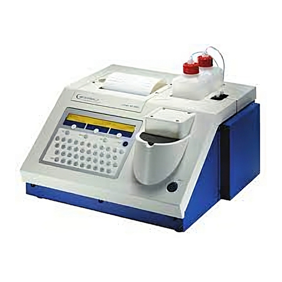
LB 9507 Chapter 2: Design of the Lumat 2. Design of Lumat LB 9507 This chapter describes the various components of Lumat LB 9507. Front view 1 Keyboard 2 Display 3 Thermal printer 4 Paper advance button 5 Reagent supply bottle (optional) - Page 24 Auxiliary board Stepper motor Tube detector Measurement chamber for turning the tube transport rotor Fig. 2-2: Inside view of Lumat Do not open the instrument! The Lumat LB 9507 must only be opened by service technicians authorised by Berthold Technologies!
- Page 25 LB 9507 Chapter 2: Design of the Lumat Rear side The rear panel of Lumat: Mains connection (115 or 230 V) Fuse with selector for voltage, display for selecting voltage Power switch Computer port (I/O port) Printer contrast adjust Display contrast adjust...
-
Page 26: Keyboard
Chapter 2: Design of the Lumat LB 9507 2.1 Keyboard The Lumat functions are directed through keyboard entries. The keyboard consists of twenty-six letter keys, twelve numerical keys, three softkeys, and five additional function keys (<enter>, <delete>, <last>, <exit> and <space>). Softkeys are keys with changing functions defined by software and shown on the display. -
Page 27: Display
2.2 Display The display located above the keyboard is a two-line LCD display, each line containing 40 characters. The LED background lighting switches on when Lumat is powered up. Functions: Entries request and display. The second line displays the functions of the softkeys, which... -
Page 28: Measurement Unit
Chapter 2: Design of the Lumat LB 9507 2.4 Measurement Unit The measurement unit is located to the right of the keyboard (see Fig. 2-1, [9]). The sample chamber is protected against dust by a semi-circular cap. The measurement chamber is located in the instrument itself and can only be accessed by removing the cover of the instrument (see Fig. - Page 29 LB 9507 Chapter 2: Design of the Lumat Tube transport rotor The tube transport rotor is made of a special conductive plastic which prevents electrostatic charges from building up. The rotor contains two holes positioned opposite each other, and each can hold a sample tube, meaning that one hole is always in loading position (at the front, facing the user) and one in measurement position.
- Page 30 Chapter 2: Design of the Lumat LB 9507 In case of need the rotor can also be turned manually (see below), so that it can be placed in positions other than the exact measurement positions. The software-controlled rotation movement positions the rotor exactly;...
- Page 31 LB 9507 Chapter 2: Design of the Lumat Tube detector At the front of the instrument is a light barrier for detecting tubes. This prevents an unloaded sample holder from moving into the measurement position. In this case injection would contaminate the inside of the measurement chamber.
-
Page 32: Reagent Storage Area
2.5 Reagent Storage Area A maximum of 2 reagent bottles are stored in an easily accessible recess on the top of Lumat. The containers are filled with the reagents required for the applications in hand, and linked to connectors 1 and 2 next to the storage bottles on the instrument by KEL/F screw joints (Fig. -
Page 33: Variable Injectors
LB 9507 Chapter 2: Design of the Lumat 2.6 Variable injectors High-precision pumps inject the reagent into the chamber. The user can define the injector volume. The integrated software allows you to select the injectors as required (no injection, injector 1, injector 2, or injector 1 and 2) and to define their volumes in 5 µL steps in the range of 25 µL to 300 µL. - Page 34 Chapter 2: Design of the Lumat LB 9507 Injector lines The connections for the injector lines on the instrument are defined as 1 (injector 1) and 2 (injector 2). Use these designations when programming measurement protocols. The injector lines lead to the corresponding pumps, and from there to the injector head.
-
Page 35: Reagent Supply
PARAMETERS> menu. This manual describes the version with 2 injectors, since this text covers all other options. So, if your Lumat does not include an injector, you can skip all information relating to injectors such as selecting injectors when creating protocols, injecting during measurement, etc. -
Page 36: Memory Management
Measurement electronic Working memory Fig. 2-12: Structure of the memory manager in Lumat LB 9507 Memory structure The internal memory contains the instrument and configuration parameters, as well as the measurement protocols and data from the 30 most recent runs. Part of this memory is used as a working memory for measurements and evaluations. - Page 37 Procedure for loading the operating software Use a PC to load the operating software from the diskette or email to Lumat. The existing software on the memory will be overwritten and all measurement protocols on the memory will be deleted, that new protocols can be stored.
- Page 38 Start the terminal program, which is along the new operating software on the diskette or email, and load the new software to Lumat. This overwrites the memory with the new operating software, deleting all measurement protocols. For better instructions see text file "READ.ME", which is included in the software update package.
-
Page 39: Getting Started
LB 9507 Chapter 3: Getting Started 3. Getting Started 3.1 Instrument Setup The place where the instrument is set up should have the following characteristics: free of dust no strong magnetic fields no direct exposure to sunlight ambient temperature +15 - +30°C... -
Page 40: Switching On Lumat
Chapter 3: Getting Started LB 9507 3.4 Switching on Lumat Please watch the display: After the power is switched on, the following messages should appear: ROTATING TO INITIALISE When this message appears, the tube transport rotor will perform a whole revolution. The ”ready” message then... -
Page 41: System Configuration Parameters
<SYSTEM CONFIGURATION> menu. They describe the general mode of operation of the LB 9507. The entry menu is accessed as follows: in the main menu (with the READY display), press the key below <OTHERS>. Press this key again in the next display. The next display appears, containing the <SYSTEM CONFIGURATION>... -
Page 42: Description Of The System Configuration Parameters
Chapter 3: Getting Started LB 9507 3.5.1 Description of the System Configuration Parameters a) Calculating the Coefficient of Variation <DATE> <TIME> SYST. CONFIG. INSTR.PARAM. -OTHERS- INSTRUMENT CONFIGURATION CV/CVD LANGUAGE -OTHERS- COEFFICIENT OF VARIATION CALCULATED FROM RLU (C.V.) CONC. (CVD.) <C.V./CVD.>: this option is available only when using the internal thermal printer. - Page 43 LB 9507 Chapter 3: Getting Started The date and time will continue to run for one month with the LB 9507 switched off. The built-in clock is supplied by a small rechargeable battery, making it independent of memory activities in the instrument.
-
Page 44: System Configuration Table
Chapter 3: Getting Started LB 9507 3.5.2 System Configuration Table Configuration Alternatives Language German/English/French Coefficient of CV or CVD variation (only required for thermal printer) Time 0 to 24 hrs or AM/PM; entry Date entry Ready beeper short, long or off... -
Page 45: Instrument Parameters
LB 9507 Chapter 3: Getting Started 3.6 Instrument Parameters 3.6.1 Setting/Verifying the Instrument Parameters The instrument parameters are those instrument settings which are valid for all measurements. This is where the mechanical times for the injector pumps and the instrument sensitivity are standardised using a certain calibration factor. - Page 46 Chapter 3: Getting Started LB 9507 Cal. Factor for red RLU Cal. Factor for black RLU Injector volume Inj. 1 (µL): Injector volume Inj. 2 (µL): red: measurement chamber marked with a red spot black: measurement chamber unmarked. Please enter these values listed in your test protocol before you start up your instrument and compare them with the printout.
-
Page 47: Changing The Instrument Parameters
LB 9507 Chapter 3: Getting Started 3.6.2 Changing the Instrument Parameters The instrument parameters of the LB 9507 are edited as follows: READY <DATE> <TIME> MEASURE PROTOCOL -OTHERS- <DATE> <TIME> OPER. FUNCT. TURN ONCE -OTHERS- <DATE> <TIME> SYST.CONFIG. INSTR.PARAM. -OTHERS- ENTER CALIBRATION FACTOR FOR RED RLU 1.00... - Page 48 Chapter 3: Getting Started LB 9507 CHANGES COMPLETE? PRINT PARAM. Entering <YES> stores the parameters and returns the program to the menu. Entering <NO> returns the program to the first instrument parameter. 3-10...
-
Page 49: Reagent Supply
LB 9507 Chapter 3: Getting Started 3.7 Reagent Supply Depending on the requirements for the luminescence reaction, the instrument may operate with 0, 1 or 2 injectors. Accordingly, you have to install one or two reagent bottles. Two empty bottles are included with the instrument. - Page 50 Chapter 3: Getting Started LB 9507 the injection lines if the instrument will not be used for a long period of time. 3-12...
-
Page 51: Safety Precautions For Operation
LB 9507 Chapter 3: Getting Started 3.8 Safety Precautions for Operation 1. Operate the instrument in dry environments only. 2. Be careful when handling strong alkaline or acidic reagents. Be sure to follow the reagent manufacturer’s safety instructions (R&S-set). 3. If there is a leak in the reagent tubing system you must abort the measurement series and eliminate the leak. -
Page 53: Structure And Operation Of Software
Chapter 4: Structure and Operation of Software 4. Structure and Operation of Software 4.1 Operation The software of the Lumat LB 9507 is menu-based. The main menu comprises 5 submenus containing a wide range of program functions. Commands or parameters are entered via the respective menus. -
Page 54: The Six Functions Of The Main Menu
4.2 The Six Functions of the Main Menu You can select various functions of the main menu from the READY screen on the Lumat LB 9507. By pressing the softkey <OTHERS> you can switch through a loop containing the various menu displays. -
Page 55: Measure> Menu
Depending on the selected protocol you will be given instructions on how to operate Lumat. <DIRECT ENTRY>Here you can enter parameters for a raw data measurement and then start the measurement directly. -
Page 56: Protocol> Menu
Chapter 4: Structure and Operartion of Software LB 9507 4.2.2 <PROTOCOL> Menu In the <PROTOCOL> menu you select the protocol types for the desired measurement mode and enter the parameters for the measurement. The following protocol types can be selected after you have selected the option <CREATE>... - Page 57 LB 9507 Chapter 4: Structure and Operation of Software <TUP/FTI> This protocol type is used to calculate the patient data using a standard. <DL-ASSAY> Automatic measurement of the Dual-Luciferase Reporter Assay. (Injection-measure-injection-measure) <REPEATED> Protocol for the measurement of long time kinetics using repeated measurements of the same sample within a fixed timed interval;...
-
Page 58: Operator Functions> Menu
Chapter 4: Structure and Operartion of Software LB 9507 4.2.3 <OPERATOR FUNCTIONS> Menu This menu includes the following user functions (for a description see Chapter 11): <REAGENT> Loading, refreshing and removing reagents and washing of injectors <PERF. TEST> Instrument and reagent test <MANUAL DATA >... -
Page 59: System Configuration> Menu
LB 9507 Chapter 4: Structure and Operation of Software 4.2.4 <SYSTEM CONFIGURATION> Menu Here you define the instrument configuration parameters: <CV/CVD> Specify here whether the coefficient of variation is to be specified in RLU (=C.V.) or in concentration units (CVD) on the thermal printout. -
Page 60: Instrument Parameter> Menu
Chapter 4: Structure and Operartion of Software LB 9507 4.2.5 <INSTRUMENT PARAMETER> Menu Enter and verify the instrument parameters, e.g. the volume of the injectors used or the calibration factors (see section 3.8). Fig. 4-6 shows you how to select this menu. -
Page 61: General Procedure
Chapter 4: Structure and Operation of Software 4.3 General Procedure The following flow chart provides an overview of the essential functions of Lumat, together with the way in which they are interrelated. More detailed information is available in the chapters listed. - Page 62 Chapter 4: Structure and Operartion of Software LB 9507 1. Getting started Connect instrument Chapter 3 Setting the instrument parameters Injector volume, calibration factors etc. Instrument configuration Language, date, time, printer Calculating the coefficient of variation Prime reagents Chap. 5 Chap.
-
Page 63: Raw Data Measurements
LB 9507 Chapter 5: Raw Data Measurements 5. Raw Data Measurements 5.1 Introduction In the Raw data measurement mode the quantity of light measured over a user-defined measuring time is measured in RLUs for each sample. You have the option of printing out a high... - Page 64 Chapter 5: Raw Data Measurements LB 9507 READY MEASURE PROTOCOL -OTHERS- Create protocol Change protocol PROTOCOL MASTER CURVE CREATE CHANGE 06: PROTOCOL NAME 06: PROTOCOL NUMBER PRINT LIST PROTOCOL 06: PROTOCOL NAME CHANGE OTHER PROT. PRINT PROT. RAW DATA CUTOFF...
-
Page 65: Creating Raw Data Protocols
LB 9507 Chapter 5: Raw Data Measurements 5.2 Creating Raw Data Protocols For routine measurements, start by entering the parameters for the measurement procedure and the evaluation strategy in a measurement protocol in the <PROTOCOL> menu, and then save them. Later, you can run a measurement simply by calling up one of these stored protocols in the <MEASURE>... - Page 66 Chapter 5: Raw Data Measurements LB 9507 READY MEASURE PROTOCOL -OTHERS- Select the <PROTOCOL> menu by pressing the button located directly below. The following display appears: PROTOCOL MASTER CURVE CREATE CHANGE The <MASTER CURVE> option is not relevant to raw data measurements.
- Page 67 LB 9507 Chapter 5: Raw Data Measurements 06: ENTER INJECTOR VOLUME 1 [µl] LAST DISPLAY Changing or confirmation of the displayed injector volume. Displayed are the standard settings for injector 1 entered in the <INSTRUMENT PARAMETERS> menu. These settings can be changed for this specific protocol.
- Page 68 Chapter 5: Raw Data Measurements LB 9507 06: DELAY TIME INJ 1 / INJ 2 (1.2 - 300.0) LAST DISPLAY Enter the desired delay in seconds (1.2 to 300 sec) between both injections and confirm with <enter>. Only if you have selected one or two injectors:...
- Page 69 LB 9507 Chapter 5: Raw Data Measurements 06: MAX. BACKGROUND [RLU/s] (0 = NONE) LAST DISPLAY Here can you define the limit value for the background. If this threshold is exceeded, you will be alerted accordingly on the display and the printout (BKG).
- Page 70 Chapter 5: Raw Data Measurements LB 9507 06:KINETICS PRINTOUT CURVE LAST DISPLAY The measurement results can be printed in the form of kinetics curve on the built-in thermal printer. 06: INPUT ALL CORRECT ? LAST DISPLAY If you select <YES> the entered parameters are stored and the program returns to the main menu (R1).
-
Page 71: Editing/Deleting Protocols
LB 9507 Chapter 5: Raw Data Measurements 5.3 Editing/Deleting Protocols READY MEASURE PROTOCOL -OTHERS- Select the <PROTOCOL> menu by pressing the button located directly below. Then follows: PROTOCOL MASTER CURVE CREATE CHANGE Select <CHANGE>. ENTER PROTOCOL NO. PRINT LIST You can print the list of stored protocols by selecting <PRINT LIST>. - Page 72 Chapter 5: Raw Data Measurements LB 9507 06: OPERATOR ID This and all the following entries can be overwritten. The following input sequence is the same as the one described in the last section starting with display R6. If you want to leave certain parameters as they are, just press <enter>.
-
Page 73: Performing Raw Data Measurements
LB 9507 Chapter 5: Raw Data Measurements 5.4 Performing Raw Data Measurements There are two ways of performing a raw data measurement: You can use a protocol which has already been created and stored. To do this, select the option <PROTOCOLS> in the <MEASURE>... - Page 74 Chapter 5: Raw Data Measurements LB 9507 06: PROTOCOL ATP-10SEC-1INJ You are prompted to confirm that this is the required protocol. If you select <NO> the program returns to display R22. <YES> leads to: COMMENT You can enter a comment on the following measurement using the alphanumeric keyboard.
- Page 75 LB 9507 Chapter 5: Raw Data Measurements BACKGROUND TOO HIGH ! This display only appears when the background threshold you have defined in the protocol is exceeded. If this happens the printout of measurement values is flagged BKG. The steps which the instrument goes through are displayed and the measurement parameters from the active protocol are printed out at the same time.
- Page 76 Chapter 5: Raw Data Measurements LB 9507 Kinetics curve (without data) selected without replicates: Up to 2000 measurement points per sample displayed as a curve (according to the measurement time) Peak maximum and total integral of each sample Kinetics curve (with data) with replicates:...
-
Page 77: Cut-Off Measurements
LB 9507 Chapter 6: CUT-OFF-Measurements 6. CUT-OFF Measurements 6.1 Introduction The aim of CUT-OFF measurements is to divide patient samples into 3 qualitative classes separated by 2 CUT-OFF thresholds (LOW and HIGH CUT-OFF) using fixed parameters and controls. The samples are marked as follows: RLU value below LOW CUT-OFF ”NEG”... - Page 78 Chapter 6: CUT-OFF-Measurements LB 9507 Since negative controls often represent an important quality criterion, limits can be set in the protocol outside which a flag is printed. (LOW/HIGH RLU FLAG NEG. STD.) Also, with replicate measurements, the values may be flagged if their variations are too high.
- Page 79 LB 9507 Chapter 6: CUT-OFF-Measurements READY MEASURE PROTOCOL -OTHERS- Create protocol Change protocol PROTOCOL MASTER CURVE CREATE CHANGE 07: PROTOCOL NAME 07: PROTOCOL NUMBER PRINT LIST PROTOCOL 07: PROTOCOL NAME CHANGE OTHER PROT. PRINT PROT. RAW DATA CUTOFF -OTHERS- DELETE PROTOCOL? 07: OPERATOR ID.
-
Page 80: Creating Cut-Off Protocols
Chapter 6: CUT-OFF-Measurements LB 9507 6.2 Creating CUT-OFF Protocols Start by entering the parameters for the measurement procedure and the evaluation method in a measurement protocol in the <PROTOCOL> menu, and then save them. Later, you can run a measurement simply by calling up one of these stored protocols in the <MEASURE>... - Page 81 LB 9507 Chapter 6: CUT-OFF-Measurements READY MEASURE PROTOCOL -OTHERS- Select the <PROTOCOL> menu by pressing the respective button. Then follows: PROTOCOL MASTER CURVE CREATE CHANGE <MASTER CURVE> relevant CUT-OFF measurements. If you press the button below <CHANGE> you can open an existing protocol by entering its protocol number, and then edit it.
- Page 82 Chapter 6: CUT-OFF-Measurements LB 9507 If you have no injectors selected (see 3.8.2) the display C15 follows. Otherwise C6 follows. 07: ENTER INJECTOR VOLUME 1 [µl] LAST DISPLAY Changing or confirmation of the displayed injector volume. Displayed are the standard settings for injector 1 entered in the <INSTRUMENT PARAMETERS>...
- Page 83 LB 9507 Chapter 6: CUT-OFF-Measurements option you want. Press <enter> to use the response displayed in the upper-right corner of the LCD. The following display is shown: 07: DELAY TIME INJ 1/INJ 2 (0.7 - 300.0) LAST DISPLAY Enter the desired delay in seconds between both injections and confirm with <enter>.
- Page 84 Chapter 6: CUT-OFF-Measurements LB 9507 07: MAX. BACKGROUND [RLU/s] (0 = NONE) LAST DISPLAY Here can you define the limit value for the background. If this threshold is exceeded, a direction is displayed and printed out. Entering “0” means “no background threshold“. As soon as you confirm the entry with <enter>...
- Page 85 LB 9507 Chapter 6: CUT-OFF-Measurements 07: REPL. OF POS. CTRL.1 (1-10) LAST DISPLAY Enter the number of replicates of the first positive control (up to 10 allowed). 07: REPL. OF POS. CTRL.2 (1-10) LAST DISPLAY Enter the number of replicates of the second positive control (up to 10 allowed).
- Page 86 Chapter 6: CUT-OFF-Measurements LB 9507 07: HIGH CUTOFF FACTOR LAST DISPLAY 07: HIGH CUTOFF LPOS FACT. LAST DISPLAY The formula for the HIGH CUT-OFF threshold is similar to this one. 07: %CV FLAG FOR NEG. CTRL. LAST DISPLAY The negative control mean value is labelled “HICV” in the result printout if its coefficient of variation is higher than the value entered here.
- Page 87 LB 9507 Chapter 6: CUT-OFF-Measurements 07: HIGH RLU FLAG NEG. CTRL. LAST DISPLAY Lower and upper limit for marking negative controls: a FLAG appears in the printout when the value is not within the specified value range. “LOW” if measured value < LOW RLU FLAG “HIGH”...
-
Page 88: Editing/Deleting Protocols
Chapter 6: CUT-OFF-Measurements LB 9507 6.3 Editing/Deleting Protocols READY <DATE> <TIME> MEASURE PROTOCOL -OTHERS - Select the <PROTOCOL> menu by pressing the respective button. Then follows: PROTOCOL MASTER CURVE CREATE CHANGE Select <CHANGE>. ENTER PROTOCOL NO. PRINT LIST The list of stored protocols can be printed by selecting <PRINT LIST>. - Page 89 LB 9507 Chapter 6: CUT-OFF-Measurements 07: OPERATOR ID This and all following entries can be overwritten. The following input sequence is the same as the one described in the last section starting with display C6. 6-13...
-
Page 90: Running Cut-Off Measurements
Chapter 6: CUT-OFF-Measurements LB 9507 6.4 Running Cut-off Measurements READY MEASURE PROTOCOL -OTHERS- Select <MEASURE>. SELECT TYPE OF MEASUREMENT ? PROTOCOLS DIRECT ENTRY RATEMETER Select <PROTOCOLS> to open a stored protocol. ENTER PROTOCOL NO. PRINT LIST The list of stored protocols including number and name can be printed by pressing the button below <PRINT LIST>. - Page 91 LB 9507 Chapter 6: CUT-OFF-Measurements REMOVE TUBE... Remove the tube from the sample holder if there is one. This display appears if there is a tube in the sample holder. So, if a tube already is in the correct position before you start measurement, you will have to lift the tube briefly.
- Page 92 Chapter 6: CUT-OFF-Measurements LB 9507 parameters from the active protocol are printed out at the same time. INJECTING ... MEASURING ... SAMPLE-RLU REMOVE BACKGR. (RLU/S) 30.0 TUBE Once measurement is complete, the first line shows the result of the measurement in RLUs, the second line (if defined in the protocol) shows the result of the background measurement.
- Page 93 LB 9507 Chapter 6: CUT-OFF-Measurements NEG. CTRL. REPL. # 2 TUBE # 2 START Start the measurement by pressing the <start> button. In accordance with the selected protocol, you are asked for the defined number of replicates for negative and then positive controls.
- Page 94 Chapter 6: CUT-OFF-Measurements LB 9507 6-18...
-
Page 95: Quantitative Measurements (Lia
LB 9507 Chapter 7: Quantitative Measurements (LIA...) 7. Quantitative Measurements (LIA...) 7.1 Introduction This type of measurement is used for reagent kit specific measurements to quantify analyte concentrations (LIA, ILMA, etc.). Three measurement strategies are available: 1. Measurement with complete standard series Known standard concentrations are measured before the unknown samples. - Page 96 Chapter 7: Quantitative Measurements (LIA...) LB 9507 READY MEASURE PROTOCOL -OTHERS- Create Protocol Enter Master Curve Master curve entry PROTOCOL MASTER CURVE CREATE CHANGE PROTOCOL NUMBER 08: PROTOCOL NAME PRINT LIST PROTOCOL # O8 "LIA" 08: PROTOCOL TYPE RAW DATA...
-
Page 97: Setting Up Quantitative Protocols
LB 9507 Chapter 7: Quantitative Measurements (LIA...) 7.2 Setting Up Quantitative Protocols Start by entering the parameters for the measurement procedure and the evaluation strategy in a measurement protocol in the <PROTOCOL> menu, and then save them. Later, you can run a measurement simply by calling up one of these stored protocols in the <MEASURE>... - Page 98 Chapter 7: Quantitative Measurements (LIA...) LB 9507 READY MEASURE PROTOCOL -OTHERS- Select the <PROTOCOL> menu by pressing the respective button. Then follows: PROTOCOL MASTER CURVE CREATE CHANGE The <MASTER CURVE> option can be used only when a “quantitative protocol” without a standard series has been created and stored.
- Page 99 LB 9507 Chapter 7: Quantitative Measurements (LIA...) 08: OPERATOR ID. Enter the user name and press <enter>. If no injectors are activated (see chapter 3.8.2) the Display L15 follows. 08: ENTER INJECTOR VOLUME 1 [µl] LAST DISPLAY Changing or confirmation of the displayed injector volume.
- Page 100 Chapter 7: Quantitative Measurements (LIA...) LB 9507 08: SEQUENCE OF INJECTIONS 1->2 1->2 2->1 LAST DISPLAY If you have defined 2 injectors, you have to define the sequence of the injections here: injector 1 first and then injector 2 or vice versa.
- Page 101 LB 9507 Chapter 7: Quantitative Measurements (LIA...) 08: AUTOMATIC BKG SUBTRACTION LAST DISPLAY Here you can select whether the background effect is to be subtracted automatically from the measured results. Remember that the statistical significance of the measured values is dependent upon the measuring time.
- Page 102 Chapter 7: Quantitative Measurements (LIA...) LB 9507 08: NO. OF DECIMAL (0-3) LAST DISPLAY Enter the desired number of decimal places for the calculated concentration in all printouts and press <enter>. 08: NO. OF CONTROLS (0-10) LAST DISPLAY Enter the number of control samples used for the measurements (0 to 10) and press <enter>.
- Page 103 LB 9507 Chapter 7: Quantitative Measurements (LIA...) 08: CONTROL 2 LOW LIMIT 0.00 LAST DISPLAY Enter the lower limit for the 2nd control sample and press <enter>. 08: CONTROL 2 HIGH LIMIT 14.00 LAST DISPLAY Enter the upper limit for the 2nd control sample and press <enter>.
- Page 104 Chapter 7: Quantitative Measurements (LIA...) LB 9507 08: REPL. OF SAMPLES (1-10) LAST DISPLAY Enter the replicate number of patient samples (1 - 10). USE COMPLETE STANDARD SERIES ? LAST DISPLAY Select <YES> to use a complete standard series. If you select <NO>...
- Page 105 LB 9507 Chapter 7: Quantitative Measurements (LIA...) 08: TRANSF. 0=LOGIT/LG 1=LG/LG LAST DISPLAY Choose whether to perform a logit-log or log-log transformation prior to the spline fit. Use Logit-log for standard curves where saturation is expected in the upper RLU range (usually preferable).
-
Page 106: Editing/Deleting Protocols
Chapter 7: Quantitative Measurements (LIA...) LB 9507 7.3 Editing/Deleting Protocols READY MEASURE PROTOCOL -OTHERS- Select the <PROTOCOL> menu by pressing the respective button. Then follows: PROTOCOL MASTER CURVE CREATE CHANGE Select <CHANGE>. ENTER PROTOCOL NUMBER ? PRINT LIST If you like you can print the list of stored protocols by selecting <PRINT LIST>. - Page 107 LB 9507 Chapter 7: Quantitative Measurements (LIA...) DELETE PROTOCOL # 8: To delete this protocol, select <YES>. To edit the protocol, select <NO>. If you do this the first entry of the protocol is displayed, i.e. the user name in display L5: 08: OPERATOR ID This and all following entries can be overwritten.
-
Page 108: Entering A Master Curve
<enter>. If these requirements are not met, an error message is displayed which you can acknowledge by pressing <exit>. If the protocol number is accepted by Lumat the following display appears: PROTOCOL # 11 "LIA" Select <YES>. Press the button below <NO> if you want to select another protocol number. - Page 109 Enter the number of curve points corresponding to the master curve and press <enter>. You can only enter RLU values in continuously rising or falling order. Lumat does not accept illegal entries and alerts you accordingly. 08: MASTER CURVE RLU 1 LAST DISPLAY Enter the RLU values for the 1st curve point.
- Page 110 Chapter 7: Quantitative Measurements (LIA...) LB 9507 08: MASTER CURVE CONC. LAST DISPLAY Enter the concentration of the 2nd curve point, and so on for all the curve points defined in L 45. An error message will be displayed if the entered value is smaller or equal to the previous value;...
-
Page 111: Performing Quantitative Measurements
LB 9507 Chapter 7: Quantitative Measurements (LIA...) 7.5 Performing Quantitative Measurements 7.5.1 Measurement with a Complete Standard Curve READY <DATE> <TIME> MEASURE PROTOCOL -OTHERS- Select <MEASURE>. SELECT TYPE OF MEASUREMENT PROTOCOLS DIRECT ENTRY RATEMETER Select <PROTOCOLS> to open a stored protocol. - Page 112 Chapter 7: Quantitative Measurements (LIA...) LB 9507 COMMENT You can enter a comment on the following measurement using the alphanumeric keyboard. Confirm it with <enter>. If you do not want to enter a comment, just press <enter>. REMOVE TUBE... Remove the tube from the sample holder if there is one. This display appears if there is a tube in the sample holder.
- Page 113 LB 9507 Chapter 7: Quantitative Measurements (LIA...) BACKGROUND TOO HIGH ! This display only appears when the background threshold you have defined in the protocol is exceeded. If this happens printout of measurement values is flagged BKG. The steps which the instrument goes through are displayed, and the measurement parameters from the active protocol are printed out at the same time.
- Page 114 The following then appears: STD # 1 REPL. # 1 TUBE # 6 INSERT TUBE ... Lumat waits for you to load the 1st standard tube. Measurement begins once you have positioned the tube and pressed the <start> button. BACKGROUND... INJECTION... MEASUREMENT... 7-20...
- Page 115 LB 9507 Chapter 7: Quantitative Measurements (LIA...) The results of the standards are continuously printed out. Once all of the standards have been measured, the quality of the results is checked before calculating the spline function. Display 69 appears if the results are correct.
- Page 116 Chapter 7: Quantitative Measurements (LIA...) LB 9507 STANDARD CURVE NOT CORRECT EXIT CHANGE At this point you can correct the curve points (assuming that there has been a systematic measurement error or that the tubes have simply been mixed up). You can also abort the measurement via <EXIT>.
- Page 117 If the standard curve fails to meet certain quality criteria (no balance point, no or one point of inflection in the lin/log representation of the values), Lumat will automatically smooth the curve and display the smoothing factor used. STANDARD CURVE:...
- Page 118 Chapter 7: Quantitative Measurements (LIA...) LB 9507 L70b CHANGE STANDARD CURVE: STANDARDS SMOOTHING LAST DISPLAY You can correct the standard values or enter a smoothing factor which differs from the automatic calculation by the program (0 to 99). The program then returns to display 70.
-
Page 119: Measurements With Master Curve
LB 9507 Chapter 7: Quantitative Measurements (LIA...) 7.5.2 Measurements with Master Curve The measurement procedure using a master curve defined in the protocol is analogous to the measurement type described above. The two calibrators are measured instead of the standards, and the program then works with the predefined master curve using this data. - Page 120 Chapter 7: Quantitative Measurements (LIA...) LB 9507 L58c HIGH CAL TUBE # 2 INSERT TUBE ... Load the 2nd calibrator and start measurement. BACKGROUND MEASUREMENT… INJECTION … MEASUREMENT… L58d SAMPLE-RLU REMOVE TUBE After you have removed the tubes you can change the values of the 2-point calibrators.
-
Page 121: T-Uptake/Fti-Measurements
FTI (Free Thyroid Index) value. This requires first conducting a T4 (or T3) assay in the previous series of tests. Because the Lumat LB 9507 always stores the measured mean concentrations of control and patient values sequentially for each... - Page 122 Chapter 8: T-Uptake/FTI-Measurements LB 9507 READY MEASURE PROTOCOL -OTHERS- Create protocol Change protocol PROTOCOL MASTER CURVE CREATE CHANGE 09: PROTOCOL NAME 09: PROTOCOL NUMBER PRINT LIST 09: PROTOCOL NAME PROTOCOL RAW DATA CUTOFF -OTHERS- CHANGE OTHER PRINT PROT. 09: PROTOCOL NAME...
-
Page 123: Creating T-Uptake/Fti Protocols
LB 9507 Chapter 8: T-Uptake/FTI-Measurements 8.2 Creating T-uptake/FTI protocols In the first step the parameters for the measurement procedure and the evaluation strategy are entered and saved in the <PROTOCOL> menu to produce a measurement protocol. Later measurements are done by retrieving one of the stored protocols in the <MEASURE>... - Page 124 Chapter 8: T-Uptake/FTI-Measurements LB 9507 READY MEASURE PROTOCOL -OTHERS- Select the <PROTOCOL> menu by pressing the button located directly below. The following display appears: PROTOCOL MASTER CURVE CREATE CHANGE The <MASTER CURVE> option can only be used when a “quantitative protocol” without a standard series has been created and saved (see section 7.2).
- Page 125 LB 9507 Chapter 8: T-Uptake/FTI-Measurements 09: OPERATOR ID. Enter the user name and press <enter>. If no injector is selected (see 3.8.2) display T15 follows. 09: ENTER INJECTOR VOLUME 1 [µl] LAST DISPLAY Changing or confirmation of the displayed injector volume.
- Page 126 Chapter 8: T-Uptake/FTI-Measurements LB 9507 09: SEQUENCE OF INJECTIONS 1->2 1->2 2->1 LAST DISPLAY If you have selected 2 injectors, you have to define the sequence of the injections here: injector 1 first and then injector 2 or vice versa. Make your selection by pressing the button below the option you want.
- Page 127 LB 9507 Chapter 8: T-Uptake/FTI-Measurements 09: AUTOMATIC BKG SUBTRACTION LAST DISPLAY Here you can select whether the background effect is to be subtracted automatically from the measured results. Remember that the statistical significance of the measured values is dependent upon the measuring time.
- Page 128 Chapter 8: T-Uptake/FTI-Measurements LB 9507 09: NUMBER OF DECIMAL PLACES (0-3) LAST DISPLAY Enter the desired number of decimal places for the calculated concentration in all printouts and press <enter>. 09: NO. OF CONTROLS (0-10) LAST DISPLAY Enter the number of control samples used for the measurements (0 to 10) and press <enter>.
- Page 129 LB 9507 Chapter 8: T-Uptake/FTI-Measurements 09: CONTROL 2 LOW LIMIT 0.000 LAST DISPLAY Enter the lower limit for the 2nd control sample and press <enter>. 09: CONTROL 2 HIGH LIMIT 0.000 LAST DISPLAY Enter the upper limit for the 2nd control sample and press <enter>.
- Page 130 Chapter 8: T-Uptake/FTI-Measurements LB 9507 09: REPL. OF SAMPLES (1-10) LAST DISPLAY Enter the replicate number of patient samples (1 - 10). 09: VALUE OF REFERENCE 0.000 LAST DISPLAY Enter the reference value in the range 0.001 - 9999. 09: USE FTI CALCULATION? LAST DISPLAY Decide whether to use FTI calculation.
- Page 131 LB 9507 Chapter 8: T-Uptake/FTI-Measurements 09: FTI EXP. RANGE HIGH LIMIT 0.000 LAST DISPLAY These inputs refer to the normal range of the FTI index for patient samples. 09: INPUT ALL CORRECT ? LAST DISPLAY If you select <YES> the entered parameters are stored and the program returns to the main menu (T1).
-
Page 132: Editing/Deleting Protocols
Chapter 8: T-Uptake/FTI-Measurements LB 9507 8.3 Editing/Deleting protocols READY MEASURE PROTOCOL -OTHERS- Select the <PROTOCOL> menu by pressing the button located directly below. The following display appears: PROTOCOL MASTER CURVE CREATE CHANGE Select <CHANGE>. PROTOCOL NUMBER ? PRINT LIST You can print a list of the stored protocols by selecting <PRINT LIST>. - Page 133 LB 9507 Chapter 8: T-Uptake/FTI-Measurements 09: OPERATOR ID. You can overwrite this and all subsequent entries. The input sequence is the same as described in the last section from display T6 onwards. Move through the entries with <enter>, and edit them by overwriting or deselecting.
-
Page 134: Performing T-Uptake/Fti Measurements
Chapter 8: T-Uptake/FTI-Measurements LB 9507 8.4 Performing T-uptake/FTI Measurements READY MEASURE PROTOCOL -OTHERS- Select <MEASURE>. MEASUREMENT MODE ? PROTOCOLS DIRECT ENTRY RATEMETER Select <PROTOCOLS>. PROTOCOL NUMBER PRINT LIST For control purposes you can print the list of stored protocols with their numbers and names by pressing the button below <PRINT... - Page 135 LB 9507 Chapter 8: T-Uptake/FTI-Measurements REMOVE TUBE... Remove the tube from the sample holder if there is one. This display appears if there is a tube in the sample holder. So, if a tube already is in the correct position before you start measurement, you will have to lift the tube briefly.
- Page 136 Chapter 8: T-Uptake/FTI-Measurements LB 9507 INJECTING ... MEASURING... SAMPLE-RLU REMOVE TUBE The first line shows the result of the measurement in RLUs, the second line (if defined in the protocol) shows the result of the background measurement. At the same time the measurement parameters defined in the protocol are printed out.
- Page 137 LB 9507 Chapter 8: T-Uptake/FTI-Measurements CTRL. # 1 REPL. # 1 TUBE # 3 INSERT TUBE... The measurement is performed and the result printed as for the standards. The patient samples are then expected: SAMPLE # 1 REPL. # 1...
-
Page 139: Dual-Luciferase Reporter Gene Assay
The Dual- Luciferase Reporter Gene Assay protocol of the Lumat LB 9507 is designed for automatic measurement of this assay. This assay is performed in the following way: after injection of the first reagent... - Page 140 Chapter 9: Dual-Luciferase Reporter Gene Assay LB 9507 READY MEASURE PROTOCOL -OTHERS- PROTOCOL MASTER CURVE CREATE CHANGE Create protocol Change protocol 06: PROTOCOL NAME 09: PROTOCOL NUMBER PRINT LIST 06: PROTOCOL TYPE PROTOCOL RAW DATA CUTOFF -OTHERS- CHANGE OTHER PRINT PROT.
-
Page 141: Creating Protocols For Dual-Luciferase
LB 9507 Chapter 9: Dual-Luciferase Reporter Gene Assay 9.1 Creating Protocols for Dual-Luciferase Assay 9.1.1 With 2 injectors installed READY MEASURE PROTOCOL -OTHERS- Select the <PROTOCOL> menu by pressing the button located directly below. The following display appears: PROTOCOL MASTER CURVE... - Page 142 Chapter 9: Dual-Luciferase Reporter Gene Assay LB 9507 06: PROTOCOL TYPE QUANT TUP/FTI -OTHERS- 06: PROTOCOL TYPE DL-ASSAY ------ -OTHERS- Select <DL-ASSAY>. Now you have to enter the parameters which are the same for all protocol types: 06: OPERATOR ID.
- Page 143 LB 9507 Chapter 9: Dual-Luciferase Reporter Gene Assay If you select <NO>, display D13 appears or, when no injector is selected, D14. <YES> takes you to the next display: 06: MEASURING TIME BKG [s] (0.1 - 200.0) LAST DISPLAY Enter between 0.1 and 200.0 seconds for the background measurement and press <enter>.
- Page 144 Chapter 9: Dual-Luciferase Reporter Gene Assay LB 9507 Enter the desired delay in seconds (0.0 to 300 sec) between the injection and the beginning of the measurement and confirm with <enter>. 06: MEASURING TIME 1 [s] (0.1 - 200.0) LAST DISPLAY Enter the desired measuring time for the first measurement (0.1 to...
- Page 145 LB 9507 Chapter 9: Dual-Luciferase Reporter Gene Assay 06: NORMALIZED RESPONSE M1/M2 M1/M2 M2/M1 LAST DISPLAY Normalized response gives the quotient of both measured values: M1/M2= RLU/s Firefly luciferase RLU/s Renilla luciferase M2/M1= RLU/s Renilla luciferase RLU/s Firefly luciferase 06: INPUT ALL CORRECT ? LAST DISPLAY If you select <YES>...
-
Page 146: With 1 Injector Installed
Chapter 9: Dual-Luciferase Reporter Gene Assay LB 9507 9.1.2 With 1 injector installed The instructions here describe how to create a protocol when only one injector is installed. This measurement mode can be used only when the starter reagent is manually injected. The Stop and Glo™... - Page 147 LB 9507 Chapter 9: Dual-Luciferase Reporter Gene Assay 06: PROTOCOL TYPE QUANT TUP/FTI -OTHERS- 06: PROTOCOL TYPE DL-ASSAY -OTHERS- Select <DL-ASSAY>. Now you have to enter the parameters which are the same for all protocol types: 06: OPERATOR ID Type the user name and press <enter>.
- Page 148 Chapter 9: Dual-Luciferase Reporter Gene Assay LB 9507 06: MEASURING TIME 1 [s] (0.1 - 200.0) LAST DISPLAY Enter the desired measuring time (0.1 to 200.0 seconds) for the first measurement for each tube and press <enter>. 06: MEASURING TIME 2 [s] (0.1 - 200.0)
-
Page 149: Without Injectors
LB 9507 Chapter 9: Dual-Luciferase Reporter Gene Assay 9.1.3 Without injectors The instructions here describe how to create a protocol when no injectors are installed. The reagents have to be injected manually between the measurements. The sample tubes are turned to the loading position and the injection can start. - Page 150 Chapter 9: Dual-Luciferase Reporter Gene Assay LB 9507 06: PROTOCOL TYPE QUANT TUP/FTI -OTHERS- 06: PROTOCOL TYPE DL-ASSAY -OTHERS- Select <DL-ASSAY>. Now you have to enter the parameters which are the same for all protocol types: 06: OPERATOR ID Type the user name and press <enter>.
- Page 151 LB 9507 Chapter 9: Dual-Luciferase Reporter Gene Assay 06: NORMALIZED RESPONSE M1/M2 M1/M2 M2/M1 LAST DISPLAY Normalized response gives the quotient of both measured values: M1/M2= RLU/s Firefly luciferase RLU/s Renilla luciferase M2/M1= RLU/s Renilla luciferase RLU/s Firefly luciferase 06: INPUT ALL CORRECT ? LAST DISPLAY If you select <YES>...
-
Page 152: Editing/Deleting Protocols
Chapter 9: Dual-Luciferase Reporter Gene Assay LB 9507 9.2 Editing/Deleting Protocols READY MEASURE PROTOCOL -OTHERS- Select the <PROTOCOL> menu by pressing the respective button. Then follows: PROTOCOL MASTER CURVE CREATE CHANGE Select <CHANGE>. ENTER PROTOCOL NO. PRINT LIST You can print the list of stored protocols by selecting <PRINT LIST>. - Page 153 LB 9507 Chapter 9: Dual-Luciferase Reporter Gene Assay 06: OPERATOR ID This and all the following entries can be overwritten. The following input sequence is the same as the one described in the last section starting with display D7. If you want to leave certain parameters as they are, just press <enter>.
-
Page 154: Performing Dual-Luciferase Reporter Gene Assay Measurements
Chapter 9: Dual-Luciferase Reporter Gene Assay LB 9507 9.3 Performing Dual-Luciferase Reporter Gene Assay Measurements You can use a protocol which has already been created and stored. To do this, select the option <PROTOCOLS> in the <MEASURE> menu. Measurement with stored protocol... - Page 155 LB 9507 Chapter 9: Dual-Luciferase Reporter Gene Assay COMMENT You can enter a comment on the following measurement using the alphanumeric keyboard. Confirm it with <enter>. If you do not want to enter a comment, just press <enter>. REMOVE TUBE...
- Page 156 Chapter 9: Dual-Luciferase Reporter Gene Assay LB 9507 BACKGROUND TOO HIGH ! This display only appears when the background threshold you have defined in the protocol is exceeded. If this happens the printout of measurement values is flagged BKG. The steps which the instrument goes through are displayed and the measurement parameters from the active protocol are printed out at the same time.
- Page 157 LB 9507 Chapter 9: Dual-Luciferase Reporter Gene Assay QUOTIENT M1/M REMOVE TUBE Once the measurement is complete, the first line shows the result of the measurement in RLUs, the second line (if defined in the protocol) shows the result of the background measurement.
- Page 158 Chapter 9: Dual-Luciferase Reporter Gene Assay LB 9507 SAMPLE 2 TUBE # 2 START Press the <Start> button. The 2nd tube is measured. If it is a replicate, “SAMPLE 1” will remain on the display until all tubes of this group have been measured, while the “TUBE #” is incremented continuously.
-
Page 159: Kinetic And Repeated Measurements
LB 9507 Chapter 10: Kinetic Measurements 10. Kinetic and Repeated Measurements There are three ways to perform kinetic measurements: Using a “RAW DATA" measurement protocol (or a "Direct Entry” measurement which is not stored in the instrument memory) you will be asked at the end of the protocol entry if you would like to use the kinetic option. -
Page 160: Repeated Measurements
Chapter 10: Kinetic Measurements LB 9507 10.2 Repeated Measurements The protocol Repeated Measurement is used for long term kinetics. Within a certain time window, samples are measured several times. The scheme of measurement time and time between single measurements is defined by the user. The sample stays inside the instrument until all single measurements are completed and the total measurement time is reached. - Page 161 LB 9507 Chapter 10: Kinetic Measurements READY MEASURE PROTOCOL -OTHERS- Create protocol Change protocol PROTOCOL MASTER CURVE CREATE CHANGE 06: PROTOCOL NUMBER 06: PROTOCOL NAME PRINT LIST PROTOCOL 06: PROTOCOL NAME CHANGE OTHER PROT. PRINT PROT. RAW DATA CUTOFF -OTHERS-...
-
Page 162: Creating Repeated Protocols
Chapter 10: Kinetic Measurements LB 9507 10.2.1 Creating Repeated Protocols For routine measurements, start by entering the parameters for the measurement procedure and the evaluation strategy in a measurement protocol in the <PROTOCOL> menu, and then save them. Later, you can run a measurement simply by calling up one of these stored protocols in the <MEASURE>... - Page 163 LB 9507 Chapter 10: Kinetic Measurements READY MEASURE PROTOCOL -OTHERS- Select the <PROTOCOL> menu by pressing the button located directly below. The following display appears: PROTOCOL MASTER CURVE CREATE CHANGE The <MASTER CURVE> option is not relevant to repeated measurements.
- Page 164 Chapter 10: Kinetic Measurements LB 9507 06: OPERATOR ID. Enter the user name and press <enter>. 06: ENTER INJECTOR VOLUME 1 [µl] LAST DISPLAY Changing or confirmation of the displayed injector volume. Displayed are the standard settings for injector 1 entered in the <INSTRUMENT PARAMETERS>...
- Page 165 LB 9507 Chapter 10: Kinetic Measurements If you have selected 2 injectors, you have to define the sequence of the injections here: injector 1 first and then injector 2 or vice versa. Make your selection by pressing the button below the option you want.
- Page 166 Chapter 10: Kinetic Measurements LB 9507 Enter the delay between the last injection and the start of the measurement in the range from 0.0 to 300 seconds and press <enter>. 06: MEASURING TIME [s] (0.1 - 200.0) LAST DISPLAY Enter the desired measuring time (0.1 to 200.0 seconds) for each data point and press <enter>.
-
Page 167: Editing/Deleting Protocols
LB 9507 Chapter 10: Kinetic Measurements 10.2.2 Editing/Deleting Protocols READY MEASURE PROTOCOL -OTHERS- Select the <PROTOCOL> menu by pressing the button located directly below. PROTOCOL MASTER CURVE CREATE CHANGE Select <CHANGE>. ENTER PROTOCOL NO. PRINT LIST You can print the list of stored protocols by selecting <PRINT LIST>. - Page 168 Chapter 10: Kinetic Measurements LB 9507 06: OPERATOR ID This and all the following entries can be overwritten. The following input sequence is the same as the one described in the last section starting with display K6. If you want to leave certain parameters as they are, just press <enter>.
-
Page 169: Performing Repeated Measurements
LB 9507 Chapter 10: Kinetic Measurements 10.2.3 Performing Repeated Measurements To perform a repeated measurement, first you have to enter a protocol as described in chapter 10.2.2. READY MEASURE PROTOCOL -OTHERS- Select <MEASURE>. SELECT TYPE OF MEASUREMENT ? PROTOCOLS DIRECT ENTRY RATEMETER Select <PROTOCOLS>... - Page 170 Chapter 10: Kinetic Measurements LB 9507 INSERT TUBE... Load the tube containing the first sample as defined in the protocol. SAMPLE 1 TUBE # 1 START Press the button beneath the <START> function or the <start> button to the right of the rotor. Both buttons do the same thing.
- Page 171 LB 9507 Chapter 10: Kinetic Measurements SAMPLE 2 TUBE # 2 INSERT TUBE ... Load the next sample tube. SAMPLE 2 TUBE # 2 START Press <START> to measure the second sample. 10-13...
-
Page 172: Ratemeter
Chapter 10: Kinetic Measurements LB 9507 10.3 Ratemeter The Lumat LB 9507 allows continuous kinetic measurements that are not based on stored protocols and provide a high degree of flexibility. Raw data are measured continuously in this ratemeter mode, and injections can be performed manually at any time. - Page 173 LB 9507 Chapter 10: Kinetic Measurements <PRINT ON> This function prints all measurement results. The display toggles to <PRINT OFF>. <TURN NEXT> The next tube is moved into the measuring chamber. <INJECTOR 1> or <INJECTOR 2> (only when 1 injector selected) If only one injector is active, pressing the button below it at any time injects into the tube in the measuring chamber.
-
Page 175: Operator Functions
LB 9507 Chapter 11: Operator Functions 11. OPERATOR Functions The <OPERATOR FUNCTIONS> menu includes the following special operator functions: <REAGENT> To load, refresh and remove the reagents and wash the injectors <PERF. TEST> To test instrument and reagents <MANUAL DATA >... -
Page 176: Reagent> Function
Chapter 11: Operator Functions LB 9507 11.1 <REAGENT> Function In the <REAGENT> menu the following reagent specific functions are available: <PRIME> Loading the injector system with reagents with a pre-defined number of injetion cycles <REFRESH> Refreshing the reagent in the injector system. This function is needed for example when the luminometer has not been used for a long period of time. -
Page 177: Loading Reagents
LB 9507 Chapter 11: Operator Functions 11.1.1 Loading reagents This function is used to fill the injector system. Three injections with the largest possible volumes will follow. REAG. FUNC.: PRIME REFRESH -OTHERS- Select <PRIME>. LOAD REAG. INJ1 INJ2 Select the injector to be filled. -
Page 178: Refreshing Reagents
Chapter 11: Operator Functions LB 9507 11.1.2 Refreshing reagents This function is used to refresh the reagents in the injector system. If the luminometer has not been used for a long period of time, the injector volume may have changed due to evaporation or changes in pressure. -
Page 179: Washing Of The Injector System
LB 9507 Chapter 11: Operator Functions 11.1.3 Washing of the injector system This function is used to clean the injector lines with wash solution or for priming them with suitable reagents for the subsequent measurements. When you select this function, you are prompted on the display to select the injector with which to perform the washing. - Page 180 Chapter 11: Operator Functions LB 9507 INSERT TUBE Place an empty tube for the outflowing liquid. After pressing <START> the tube will move into the measurement position and the washing function will be run: INJECTION 1 1, 2, 3…x TIMES The entered number of injections will be performed.
-
Page 181: Removing Reagents
LB 9507 Chapter 11: Operator Functions 11.1.4 Removing reagents After a measurement, the (valuable) reagents in the injector lines can be pumped back into the supply bottles. READY MEASURE PROTOCOL -OTHERS- READY OPER. FUNCT. TURN ONCE -OTHERS- OPER. FUNCT.: REAGENT PERF.TEST... -
Page 182: Performance Test
Chapter 11: Operator Functions LB 9507 11.2 Performance test The <PERF. CHECK> function provides a quality test of the instrument and reagents. A few samples with isolated, known label concentration must be ready, and their values must be known. The instrument accepts 1 - 10 replicates from each category (chem. -
Page 183: Manual Data Entry
LB 9507 Chapter 11: Operator Functions low check TARE DYNAMICS = chemical background high check - chemical background NET DYNAMICS = low check - chemical background After completing the measurements, you can compare these results with the expected values and determine whether the instrument and reagents are as they should. -
Page 184: Retrieval Of Stored Data
Each measurement stored in LB 9507 is accessed by a run number which you can use to retrieve a certain measurement again. The highest number is always the most recent measurement;... -
Page 185: Rerun Of A Full Standard Protocol
LB 9507 Chapter 11: Operator Functions 11.4.1 Rerun of a Full Standard Protocol OPERATOR FUNCTIONS: DATA EVALUATION: MANUAL DATA RERUN -OTHERS- Starting point for the Rerun option. RUN 30 PROT 12 PROLACT JAN 18 14:32 PREV. RUN PRINT LIST ENTER The last measurement with run no., protocol no. - Page 186 Chapter 11: Operator Functions LB 9507 EVALUATE RUN 28 WITH PROT 07 ? You are prompted to confirm whether to evaluate the selected measurement with the same protocol that was used for the original measurement or manual entry. Normally, you will select <YES>...
- Page 187 LB 9507 Chapter 11: Operator Functions CHANGE CURVE STANDARDS SMOOTHING LAST DISPLAY This display lets you change the original ‘standard’ RLU values or modify the automatically selected smoothing factor, which is calculated when the instrument shows this display. After making the changes, return to the display G7.
-
Page 188: Rerun Of A 2-Point Calibrator Protocol
Chapter 11: Operator Functions LB 9507 11.4.2 Rerun of a 2-Point Calibrator Protocol OPERATOR FUNCTIONS: MANUAL DATA RERUN -OTHERS- Starting point for the Rerun option. RUN 30 PROT 12 PROLACT JAN 18 14:32 PREV. RUN PRINT LIST ENTER The last measurement with run No., protocol No. and name, date and time of the measurement is shown in the first line. - Page 189 LB 9507 Chapter 11: Operator Functions EVALUATE RUN 28 WITH PROT 07 ? You are prompted to confirm whether to evaluate the selected measurement with the same protocol that was used for the original measurement or manual entry. Normally, you will select <YES> here, but in special cases you can also select (the ‘dangerous’...
- Page 190 Chapter 11: Operator Functions LB 9507 CHANGE 2-POINT CALIBRATORS ? After noting the calibrators you can change the mean value of the calibrators to obtain correct control and patient values. After running through the correction sequence and confirming the prompt “CHANGES COMPLETED ?”, display G9 appears.
-
Page 191: Connection To External Computers
12.1 General The connection cable with a 9-pin connector (ID 26204) allows the LB 9507 to output the measured raw data and the calculated single and averaged concentration values. For details of handling data transfer under the Windows user interface of your PC, please refer to the appendix A-3. -
Page 192: Rs 232 Data Output Lb 9507 In Protocol-Specific Measuring Mode
Chapter 12: Connection to External Computers LB 9507 12.2 RS 232 Data Output LB 9507 in Protocol-Specific Measuring Mode Start of measurement series ? <Prot. no.> (CR) (LF) 3 digits <Gen. note> (CR) (LF) 0 - 15 digits Measured standards <RLU>... - Page 193 LB 9507 Chapter 12: Connection to External Computers FTI values Following the mean U-uptake concentration according to 12.2.6: <FTI value> <RLU> (CR) (LF) Format: 8 digits before and 3 after decimal point, “<“ or “>” if out of range, and 13 spaces if...
-
Page 194: Data Output In Raw Data Measurements
Chapter 12: Connection to External Computers LB 9507 12.3 Data Output in Raw Data Measurements Output of the measured RLU: <RLU> (CR) (LF) <RLU> (CR) (LF) <RLU> (CR) (LF) etc. 12.4 Data Output after Manual Input of RLU Values For calculation in concentration units according to the protocol. -
Page 195: Maintenance
LB 9507 Chapter 13: Maintenance 13. Maintenance 13.1 Supplying Paper 1. Open the cover of the paper feeder 2. Remove the empty paper sheath and insert the pin into the core of the new roll. 3. Remove the adhesive tape from the paper roll. -
Page 196: Replacing The Mains Fuse
Chapter 13: Maintenance LB 9507 13.2 Replacing the Mains Fuse The mains fuses are located on the rear panel of Lumat. The fuse holder and mains connection socket form a single unit. Fuse compartment Snapper Figure 13-3: Fuse compartment at the mains socket... -
Page 197: Changing The Operating Voltage
LB 9507 Chapter 13: Maintenance Fuse: 90 – 240V, 1 A slow blow CAUTION: Use only these specified fuse values when replacing the fuse. The 1 A fuse must be IEC approved and must be UL listed (note labels and markings). -
Page 199: Troubleshooting
LB 9507 Chapter 14: Troubleshooting 14. Troubleshooting 14.1 Error Messages during Operation Display Possible reason Solution BACKGROUND EFFECT Wrong entry for background effect Change protocol entry TOO HIGH in measurement protocol Measurement chamber sealing Call Technical Service elements malfunctioning Measurement chamber contaminated... -
Page 200: Other Errors
Chapter 14: Troubleshooting LB 9507 14.3 Other Errors Display Possible reason Solution Tube stuck in Rotor dirty or incorrect Call Technical Service sample holder tube measurements Rotor not turning, Measurement chamber soiled Call Technical Service but drive works No display after switching... -
Page 201: Technical Specifications Of Lb 9507
LB 9507 Chapter 15: Technical Specifications 15. Technical Specifications of LB 9507 Injectors: 0, 1 or 2 Injector volume: Adjustable by the user to a volume between 25 µL and 300 µL in 5 µL steps. ∅ Sample tubes: 12 mm x height 75 mm. - Page 202 Chapter 15: Technical Specifications LB 9507 Luminescence immunoassay protocols (all protocols: max. 40) Algorithm for calculating the standard curves: Spline function based on a logit-log calculation or log-log transform. Followed by automatic manual smoothing. Corrective calculations for ideal curve adaptation.
- Page 203 LB 9507 Chapter 15: Technical Specifications Interfaces: 1 x RS 232 (computer) Dimensions: width: 370 mm, height: 260 mm, depth: 520 mm Weight: approx. 12 kg Mains supply: 90 V up to 240 V Multi-Range Power consumption: max. 60 VA...
-
Page 205: Flow Diagram Of The Measurement Procedure
16. Flow diagram of the measurement procedure The following information provides a guide to the measurement procedure and the menu system of the Lumat software. The following table is a schematic representation of the measurement procedure and user actions, instrument actions and instrument displays. -
Page 207: Appendix
LB9507 Appendix Appendix... -
Page 208: Mathematical Basis
Appendix LB 9507 A.1 Mathematical Basis A.1.1 Overview of the Mathematical Data Reduction This chapter provides an overview of the LIA data reduction which is performed after the measurement of a full standard curve. The following steps take place one after another: The ZERO concentration factor ”f”... - Page 209 LB9507 Appendix With these pairs of the transformed standard values c and b cubic spline polynomials are calculated between all points; after this, automatic smoothing is applied when more than one turning point or one or several points with a horizontal tangent are found within the curve, provided the auto smooth function has been enabled in the system configuration menu.
-
Page 210: Variable Zero Concentration Factor
Appendix LB 9507 A.1.2 Variable Zero Concentration Factor Prior to the transformation of the concentration values, a fraction f of the second standard is added to each value if the first concentration value is zero, as follows: B - NSB... -
Page 211: Spline Function
S. The automatic smoothing function of Lumat ensures that, beginning with smoothing factor 0, the standard curve in the lin- log plot (which is only used for this!) is checked. It must have either no turning point or just one. -
Page 212: Calculation Of A Variable Reference Value
Appendix LB 9507 When using a manually smoothed spline with a smoothing factor which is larger than the one that was calculated automatically it is recommended that you print out the curve plot, since there is always the danger that the deviation from the original points may become too large. -
Page 213: Extrapolation Of The Concentration
LB9507 Appendix A.1.5 Extrapolation of the Concentration If the measured patient concentration is above the standard curve range, a linear extrapolation of the measured value is calculated and printed out up to 4 times the value of the highest standard. The calculation is done according to the following formula: B - B = C +... -
Page 214: Data Acquisition Of The Lumat Lb 9507
Saving this Data in a MS-DOS ASCII-File The “Terminal” program that is included with the MS-Windows 3.x accessories can be used for data acquisition of the Lumat LB 9507 via the serial interface RS 232. To ensure error-free data transfer, select the following terminal settings on the [ Settings ]... -
Page 215: Connection Cable Lumat/Apple Macintosh Computer
LB 9507 Appendix A.3 Connection Cable Lumat/Apple Macintosh Computer RS-232 Interface Cable for Connection of BERTHOLD Technologies Luminometers to Apple Macintosh Computers Apple Macintosh: RS-422 Mini-8 BERTHOLD Luminometer: RS-232 DB-25 (female) For the LB9507 use a gender changer 9 pin to 25 pin... -
Page 216: Background Measurement
Appendix LB 9507 A.4 Background measurement Background measurement is performed with instruments with one or two injectors installed. This measurement is used for detection the luminescence and phosphorescence background of the instrument, the sample tube and the sample. Performing a background measurement The user can define when creating protocols whether a background measurement is to be performed. - Page 217 LB 9507 Appendix 06: AUTOMATIC BKG SUBTRACTION LAST DISPLAY Here you can select whether the background effect is to be subtracted automatically from the measured results. Remember that the statistical significance of the measured values is dependent upon the measuring time.
-
Page 218: Overload Detection
Appendix LB 9507 Overload Detection The photomultiplier of Lumat LB 9507 includes an overload detection function which protects it from luminous intensity. If the luminous intensity exceeds the limit value the high voltage will be switched off. Instead of a measurement value the output < OVERLOAD > is printed in the measurement data printout. -
Page 219: Glossary
LB 9507 Appendix A.6 Glossary 1. Activator Reagents: The reagents required to initiate the light emission, e.g. microperoxidase and H The starter reagents can be injected successively from two bottles, or, pre-mixed, from one bottle. 2. Master Curve: The kit manufacturer calculates an average standard curve using many assays of the same type (for example, measured over a period of several days, by different operators). - Page 220 Lumat can only supply results if a protocol is called which has been defined earlier. 14. RLU:...
- Page 221 LB 9507 Appendix Index Luciferin 9-1 Ambient temperature 15-3 ASCII-File 8 Macintosh Computer 10 Mains connection 2-4 Master Curve 4-4, 7-14, 7-25, 14 Chemiluminescence I, 1-1, 1-8 Measurement chamber 1-4, 1-5, 1-11, 2-1, Coefficient of variation 1-1, 1-2, 3-4, 4-7, 5-...
- Page 222 Appendix LB 9507 TM 9-1 REAGENTS 2-14, 3-12, 4-6, 11-1 , 11-2 , 11- Stop and Glo Remote control 12-1 Thermal printer 1-3, 1-6, 2-6 , 3-4, 3-6, 5-7, Removing reagents 11-7 5-8, 10-1 Renilla reniformis 9-1 TIME 3-2, 3-3, 3-4, 3-5, 3-8, 3-10, 4-2, 4-7,...
Need help?
Do you have a question about the LB 9507 and is the answer not in the manual?
Questions and answers