
Subscribe to Our Youtube Channel
Related Manuals for TSI Incorporated 3480

Summary of Contents for TSI Incorporated 3480
- Page 1 Aerosol Generators Model 3480 Electrospray Aerosol Generator User’s Manual P/N 1933793, Revision E March 2008...
- Page 3 Product Overview Unpacking and Setting Up the System Model 3480 Controls, Indicators, and Electrospray Connectors Aerosol Generator Operating the Electrospray User’s Manual Maintenance Troubleshooting Contacting Customer Service Appendixes...
- Page 4 M a n u a l H i s t o r y The following is a manual history of the Model 3480 Electrospray Aerosol Generator (Part Number 1933793). Revision Date Preliminary Version March 1999 Final May 1999 July 2000...
- Page 5 Part Number 1933793 / Revision E / March 2007 Copyright ©TSI Incorporated / 2008 / All rights reserved. Address TSI Incorporated / 500 Cardigan Road / Shoreview, MN 55126 / USA Fax No. 651-490-3824 E-mail Address particle@tsi.com Limitation of Warranty...
-
Page 7: Table Of Contents
C o n t e n t s Manual History ..............iv Warranty................. v Safety ..................xi Labels ..................xi Description of Caution/Warning Symbols ......xii Caution ................xii Warning ................xiii Caution or Warning Symbols..........xiii Radiation Safety ..............xiii Chemical Safety ..............xiv Electrical Safety ..............xv About This Manual .............. - Page 8 Replacement Parts .............. 5-19 CHAPTER 6 Troubleshooting..........6-1 Electrospray Operation is Unstable ........6-1 Unplugging the Capillary............6-3 Applying Back Pressure to the Capillary ......6-3 CHAPTER 7 Contacting Customer Service......7-1 Technical Contacts..............7-1 Returning the Electrospray for Service ........7-1 viii Model 3480 Electrospray Aerosol Generator...
- Page 9 2-1 Bottom View of Electrospray Aerosol Generator Showing Location of Rubber Feet..........2-2 2-2 Installing the Ionizer............2-6 3-1 Front Panel of the Model 3480 Electrospray Aerosol Generator ..............3-2 3-2 Back Panel of the Model 3480 Electrospray Aerosol Generator ..............3-4 3-3 ANALOG OUTPUT Pin Designations........
- Page 10 6-1 Troubleshooting if the Electrospray Operation is Unstable................ 6-2 6-2 Troubleshooting if the Capillary has Become Plugged ..6-3 A-1 Specifications of the Model 3480 Electrospray Aerosol Generator ..............8-1 B-1 Capillary Flow Characteristics for Water at 20°C ....B-3...
-
Page 11: Safety
C a u t i o n If the Model 3480 is used in a manner not specified by the manufacturer, the protection provided by the equipment may be impaired. W A R N I N G High voltage is accessible in several locations within this instrument. -
Page 12: Description Of Caution/Warning Symbols
D e s c r i p t i o n o f C a u t i o n / W a r n i n g S y m b o l s The following symbol and an appropriate caution statement are used throughout the manual and on the Model 3480 to draw attention to any steps that require you to take cautionary measures... -
Page 13: Warning
Indicates the connector is connected to earth ground and cabinet ground. Warns you that the Model P-2042 Nuclespot Local Air Ionizer, which is installed inside the Model 3480 Electrospray Aerosol Generator, contains Polonium-210, a radioactive material that is subject to the regulations of the U.S. Nuclear Regulatory Commission and local regulations. -
Page 14: Chemical Safety
W A R N I N G Corrosive materials can degrade the stainless steel and aluminum chamber inside the Electrospray Aerosol Generator. Do not operate the Electrospray with chemicals that corrode stainless steel or aluminum. Model 3480 Electrospray Aerosol Generator... -
Page 15: Electrical Safety
W A R N I N G High concentrations of aerosols can be hazardous. Use a filter at the Electrospray exit if the generated aerosol is not being used by another instrument or in another application. E l e c t r i c a l S a f e t y The Electrospray Aerosol Generator contains a high-voltage source on the inside of the instrument. -
Page 17: About This Manual
This is an instruction manual for the operation and handling of the Model 3480 Electrospray Aerosol Generator. R e l a t e d P r o d u c t L i t e r a t u r e... -
Page 18: Submitting Comments
If the comment sheet has already been used, send your comments TSI Incorporated 500 Cardigan Road Shoreview, MN 55126 U.S.A. Fax: (651) 490-3824 E-mail Address: particle@tsi.com xviii Model 3480 Electrospray Aerosol Generator... -
Page 19: Product Description
C H A P T E R 1 P r o d u c t O v e r v i e w This chapter describes the Model 3480 Electrospray Aerosol Generator and gives an overview of how it works. -
Page 20: Applications
. This produces a sheath flow, which transports the droplets to the Electrospray chamber. The highly charged droplets are neutralized by a radioactive ionizer (Polonium-210), and the liquid is evaporated before the aerosol exits the instrument. Model 3480 Electrospray Aerosol Generator... -
Page 21: Packing List
U p t h e S y s t e m Use this information in this chapter to unpack and set up the Model 3480 Electrospray Aerosol Generator. P a c k i n g L i s t As you unpack the shipping container, make certain the shipment is complete. -
Page 22: Mounting The Instrument
Also, the cabinet should be set on a clean, hard surface so that the intake air can move freely under the base of the cabinet. 2–2 Model 3480 Electrospray Aerosol Generator... -
Page 23: Checking The Zero Of The Pressure Gauge
Checking the Zero of the Pressure Gauge The pressure gauge is adjusted to the zero position at the factory; however, if the needle is not lined up with the left side of the zero box marked on the gauge, you will need to re-zero the pressure gauge (see Figure 3-1). -
Page 24: Analog Output
2.5 to 50 lb. The recommended pressure of the CO supply used with the Electrospray is 5 psi. ® Swagelok is a registered trademark of Swagelok Company. 2–4 Model 3480 Electrospray Aerosol Generator... -
Page 25: Installing The Ionizer
W A R N I N G Supplying more than 15 PSI CO pressure will cause the internal silicone tubing to disconnect from the CO rotameter fitting. In addition, a higher inlet pressure makes it more difficult to adjust the CO flow rate. -
Page 26: Model 3480 Electrospray Aerosol Generator
Ionization Chamber Dummy Source O-Ring (2501027) Ionizer Retainer Figure 2-2 Installing the Ionizer 2–6 Model 3480 Electrospray Aerosol Generator... -
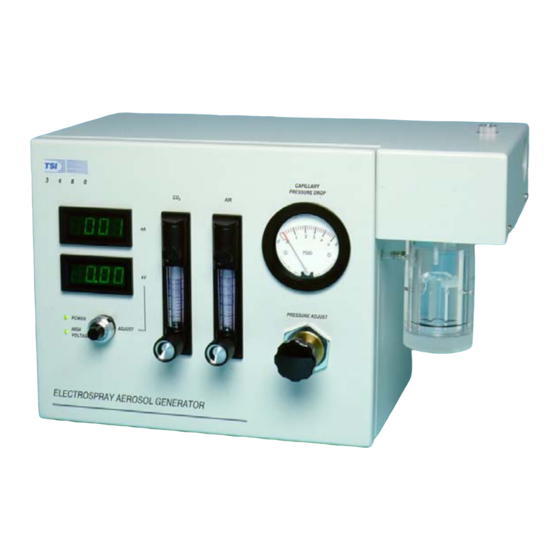
Page 27: Front Panel
LED Displays There are two LED displays on the Model 3480: Voltage (kV) and Current (nA). The voltage LED display is a measure of the high voltage applied to the platinum wire, which charges the liquid in the vial and capillary. -
Page 28: Voltage Adjustment Knob
Pressure Chamber Pressure Regulator Pressure Gauge Figure 3-1 Front Panel of the Model 3480 Electrospray Aerosol Generator Indicators There are two status LED’s on the Electrospray: power and high voltage. The green power LED indicates that power is supplied to the instrument. -
Page 29: Rotameters
Rotameters The rotameters regulate the flow rates of air and CO to the Electrospray chamber. The air and CO flow rates are typically 1.0 and 0.1 L/min, respectively. Pressure Regulator and Gauge The pressure drop across the capillary is regulated and measured with these two components. -
Page 30: Back Panel
Filtered Air Inlet Analog Output AC Power Connector Figure 3-2 Back Panel of the Model 3480 Electrospray Aerosol Generator Aerosol Exit Flexible tubing with a diameter slightly less than ¼” or any ¼” Swagelok®-type fitting can be attached to the aerosol exit. -
Page 31: Analog Output
Analog Output The analog output is a standard 15-pin D-sub connection that allows analog signals to be read by an external instrument to collect Electrospray voltage and current information. The pin designations and signal connections are shown in Figure 3-3 and Table 3-1, respectively. -
Page 32: Internal Components
The high- voltage shield covers the high-voltage fitting to protect the user from accidental electrical shock. 3–6 Model 3480 Electrospray Aerosol Generator... -
Page 33: Power Supply
Electrospray Chamber Capillary Sleeve Capillary Filters (4) High Voltage Fitting and Shield Interlock Switch Power Supply Main PCB High Voltage Supply Module Figure 3-4 Main Internal Components Power Supply 15V is supplied to the main PCB by the 25W power supply. The power supply contains no user serviceable parts. -
Page 34: Interlock Switch
See Appendix B, “Theory of Operation” for a flow schematic of the Electrospray and see Chapter 5, “Maintenance” for information related to the maintenance of these filters. 3–8 Model 3480 Electrospray Aerosol Generator... -
Page 35: Preparing Samples
E l e c t r o s p r a y Use the information in this chapter to become familiar with how to prepare liquid solutions and operate the Model 3480 Electrospray Aerosol Generator. P r e p a r i n g S a m p l e s Samples can be prepared and stored using commercially available materials, handling procedures, and storage equipment. -
Page 36: Preparing A Buffer Solution
A conductivity meter is useful for measuring the conductivity of a buffer solution. The conductivity can be increased or decreased by adding ammonium acetate or ultrapure water, respectively, to the buffer solution. Although the Electrospray will operate at a wide 4–2 Model 3480 Electrospray Aerosol Generator... -
Page 37: Measuring And Adjusting Ph
range of conductivities, a 0.2 S/m buffer solution is typically used. An experimental analysis of the useful range of liquid conductivity as a function of liquid flow rate using an electrospray method is discussed in the following journal article: Chen, Da-Ren, David Y.H. Pui, and Stanley L. Kaufman [1995] “Electrospraying of Conducting Liquids for Monodisperse Aerosol Generation in the 4 nm to 1.8 µm Diameter Range.”... -
Page 38: Selected Proteins And Their Diameters
C a u t i o n Some proteins may be dangerous to emit into the environment. Filter dangerous aerosols before emitting them into the environment. 4–4 Model 3480 Electrospray Aerosol Generator... -
Page 39: Starting Up The Electrospray
Table 4-1 Selected Proteins and Their Diameters Protein Diameter (nm) Ubiquitin Bovine Serum Albumin Ferritin S t a r t i n g U p t h e E l e c t r o s p r a y After the Electrospray system has been set up (see Chapter 2, “Unpacking and Setting Up the System”) and samples have been... -
Page 40: Generating Aerosols
Electrospray operating modes. Four distinct modes (see Figure 4-2) can be observed through the viewing window or by the current LED display as the electric field is increased by increasing the high voltage: Dripping mode, Pulsating mode, Cone-Jet mode, 4–6 Model 3480 Electrospray Aerosol Generator... -
Page 41: Three Views Of Capillary Tip Through The Viewing Window
and Corona Discharge mode. Figure 4-2 shows three photographs of the capillary tip viewed through the viewing window. Figure 4-2 Three Views of Capillary Tip Through the Viewing Window: (1) No liquid flow, (2) Liquid flow but no electric field (Dripping mode), (3) Liquid flow and an electric field (Cone-Jet mode). -
Page 42: Changing Samples
The capillary should be cleaned and cleared of liquid before shutting down the Electrospray to avoid deposits on the inside of the capillary. Follow the procedure below (see “Starting Up the Electrospray” for details) to shut down the Electrospray. 4–8 Model 3480 Electrospray Aerosol Generator... -
Page 43: Chapter 5 Maintenance
C a u t i o n Buffer should be run before shutting down the Electrospray to clean the capillary. Subsequently, the Electrospray should be run without a sample to allow the air to clear the capillary of liquid. Follow the procedure in this section to prolong capillary life and to avoid deposits on the inside of the capillary. -
Page 45: Periodic Maintenance
C H A P T E R 5 M a i n t e n a n c e This chapter gives maintenance and service procedures for the Electrospray. P e r i o d i c M a i n t e n a n c e Periodic cleaning of several parts of the Electrospray is necessary to ensure proper performance. - Page 46 2 minutes because capillary etching may become significant more quickly than for the 20 mM KOH solution. ® TWEEN is a registered trademark of Uniqema, a business unit of ICI Americas Inc. 5–2 Model 3480 Electrospray Aerosol Generator...
-
Page 47: Cleaning The Orifice Plate
Cleaning the Orifice Plate W A R N I N G High voltage is accessible in several locations within this instrument. Make sure you unplug the power source before removing the cover or performing maintenance procedures. The orifice plate is permanently attached to the inlet fitting of the Electrospray chamber to ensure electrical contact. -
Page 48: Cleaning The Aerosol Exit Port
5. If necessary, the O-rings can be removed from the viewing window mount and the viewing window mount can be cleaned using a soft cloth soaked in alcohol or a mild detergent. 5–4 Model 3480 Electrospray Aerosol Generator... -
Page 49: Replacing The Ionizer
6. Replace the lens in the viewing window mount, making sure the O-rings are installed properly. The flat side of the lens should be facing the O-ring. Lens Ring Retainer Lens O-Ring (2501010) Viewing Window Mount O-Ring (2501862) Figure 5-2 Viewing Window Assembly 7. -
Page 50: Cleaning The Electrospray Chamber
2. Remove the ionizer using the ionizer retainer tool supplied in the accessory kit and place the ionizer in a safe place. Use Figure 2-2 as a guide if necessary. 5–6 Model 3480 Electrospray Aerosol Generator... -
Page 51: Cleaning The Electrospray Chamber
Aerosol Exit Tube Exit Manifold Block O-Ring (2501029) Ionization Chamber Inlet Manifold Block Viewing Window Lens Assembly Hex Nut Common Ground Screw Inlet Fitting Hex Nut Capillary Inserts Here Figure 5-3 Cleaning the Electrospray Chamber 3. Remove the common ground screw on the side of the Electrospray chamber. -
Page 52: Performing An Air Leak Test
Electrospray chamber has been reassembled, perform a leak test to assure proper operation. Use these steps to check the entire instrument for leaks. Skip to the next section if you want to isolate the Electrospray chamber and check it for leaks. 5–8 Model 3480 Electrospray Aerosol Generator... - Page 53 W A R N I N G High voltage is accessible in several locations within this instrument. Make sure you unplug the power source before removing the cover or performing maintenance procedures. Leak Checking the Entire Electrospray Instrument 1. Remove power from the instrument and turn off all flows. 2.
-
Page 54: Cleaning The Pressure Chamber
3. Remove the screw attaching the high-voltage cable to the fitting on top of the pressure chamber. The fitting can then be removed by twisting counter-clockwise, using caution not to bend or damage the platinum high-voltage wire. 5–10 Model 3480 Electrospray Aerosol Generator... -
Page 55: Cleaning The Pressure Chamber
C a u t i o n When removing the fitting on top of the pressure chamber, use caution not to bend or damage the platinum high-voltage wire. 4. Clean the top and bottom of the pressure chamber using a soft cloth or cotton swab moistened with alcohol or a mild detergent. -
Page 56: Special Maintenance
2. Remove the cover by loosening the four screws securing the cover (they do not have to be removed) and pulling the cover upward while pushing down on the top of the front panel of the instrument or on the viewing window mount. 5–12 Model 3480 Electrospray Aerosol Generator... -
Page 57: Removing Or Installing The Capillary
Inlet Fitting Hex Nut Capillary High Voltage Shield Capillary Sleeve High Voltage Fitting Hex Nut Figure 5-5 Removing or Installing the Capillary 3. Loosen the hex nut on the inlet fitting but do not remove it. 4. Carefully pull the capillary from the capillary guide leaving the guide behind. -
Page 58: Cleaning The Capillary Tip
8. Turn on the power to the instrument. If the cover is removed, high voltage will not be supplied to the instrument, but the capillary viewing window LED will turn on. 5–14 Model 3480 Electrospray Aerosol Generator... -
Page 59: Adjusting The Position Of The Capillary Tip
9. Carefully insert the capillary tip into the capillary guide. While looking through the viewing window, continue pushing the capillary into the capillary guide until the tip of the capillary first appears, then tighten the hex nut on the inlet fitting. 10. -
Page 60: Reversing The High-Voltage Polarity
In a positive module (shown), the high-voltage power supply is located on the exposed side of the high-voltage PCB. In a negative module, the high-voltage power supply is located on the opposite side of the high- voltage PCB. 5–16 Model 3480 Electrospray Aerosol Generator... -
Page 61: Determination Of High-Voltage Polarity
High Voltage Module High Voltage High Voltage Power Supply Figure 5-6 Determination of High-Voltage Polarity The standard Electrospray is equipped with a positive high-voltage module, which causes the generated droplets to initially have a high-positive charge. However, if initially negatively charged droplets are desired, a negative high-voltage module is available from TSI. -
Page 62: Reversing The High Voltage Polarity
There is a -turn spring locking connect that secures the connector when it is seated properly. 8. Replace the cover on the instrument and tighten the four screws that secure the cover. 5–18 Model 3480 Electrospray Aerosol Generator... -
Page 63: Cleaning The Pressure Regulator
Because the level of contaminants entering the Electrospray in the air and CO is low, the four internal filters in the Model 3480 do not need to be replaced under normal operating conditions. R e p l a c e m e n t P a r t s This subsection contains information on replacement parts available from TSI and their part numbers. - Page 64 (please specify positive or negative) Capillaries 25 µm (25 per pack) 3900124 Capillaries 30 µm (25 per pack) 3900125 Capillaries 40 µm (25 per pack) 3900126 Capillary Sleeve Guide 1705014 Neutralizer 348002 Filter, Balston BX on T-Connector 1602230 5–20 Model 3480 Electrospray Aerosol Generator...
-
Page 65: Electrospray Operation Is Unstable
C H A P T E R 6 T r o u b l e s h o o t i n g This chapter lists potential problems and their solutions. E l e c t r o s p r a y O p e r a t i o n i s U n s t a b l e If the Electrospray is not operating in the Cone-Jet mode (see Chapter 4, “Operating the... -
Page 66: Troubleshooting If The Electrospray Operation Is Unstable
There is no current reading Make sure the voltage, pressure, and flow rates are adjusted properly Make sure the capillary is immersed in the sample vial solution Make sure the platinum wire is immersed in the sample vial solution Model 3480 Electrospray Aerosol Generator... -
Page 67: Unplugging The Capillary
U n p l u g g i n g t h e C a p i l l a r y Each capillary is checked before leaving the factory to ensure proper operation. However, a capillary can become fully or partially plugged due to several reasons, including those listed in Table 6-2. - Page 68 If bubbles are not seen after 5 minutes at 5 psi back pressure, refer to the alternative solutions mentioned earlier in this chapter to unplug the capillary. Model 3480 Electrospray Aerosol Generator...
-
Page 69: Technical Contacts
This chapter gives directions for contacting people at TSI Incorporated for technical information and directions for returning the Model 3480 Electrospray for service. T e c h n i c a l C o n t a c t s... - Page 70 Note: The ionizer must be replaced 12 months from the date on the ionizer label. Contact TSI to order a new ionizer four weeks before the ionizer expiration date. When returning an ionizer, contact TSI for handling and shipping instructions. Model 3480 Electrospray Aerosol Generator...
-
Page 71: Specifications Of The Model 3480 Electrospray Aerosol Generator
M o d e l 3 4 8 0 S p e c i f i c a t i o n s The following specifications—which are subject to change—list the most important features of the Model 3480 Electrospray Aerosol Generator. Table A-1... -
Page 72: Pressure Regulator Maintenance
Over-voltage category II Pollution degree II *TSI Incorporated is authorized by the United States Nuclear Regulatory Commission to distribute these Ionizers. If your location is within the United States, no other federal license is required. Check local regulations for your own protection. Ionizers are shipped separately. End-user name and address is required. -
Page 73: Rotameter Maintenance
Rinse all parts with clean water and dry thoroughly. Avoid use of solvents and strong bases for cleaning. Reassemble by reversing above. Figure A-2 Rotameter Back View Model 3480 Specifications... -
Page 75: System Description
A P P E N D I X B T h e o r y o f O p e r a t i o n This appendix describes theories of operation for the Electrospray Aerosol Generator. S y s t e m D e s c r i p t i o n The Electrospray consists of three main subsystems that are used to generate a monodisperse aerosol. -
Page 76: Capillary Flow Characteristics
(¼ atm), and the viscosity of water at 20°C is 0.89E-2 poise. Given these conditions, the nominal liquid flow rate is 66 nL/min. Table B-1 lists values of the liquid flow rate as a function of B–2 Model 3480 Electrospray Aerosol Generator... -
Page 77: B-1 Capillary Flow Characteristics For Water At 20°C
pressure and capillary diameter. Also included in the table is the volume of the capillary, residence time of the liquid in the capillary, and the length of time for 1 mL to flow through the capillary. Table B-1 Capillary Flow Characteristics for Water at 20°C Capillary Capillary Inner Liquid Flow... -
Page 78: Calculating Primary Droplet Diameter
Polonium-210 radioactive alpha-emitter ionizer. The nature of the flow through the orifice plate into the ionization chamber and the placement of the ionizer cause the droplets to encounter the ions nearly immediately upon their formation. B–4 Model 3480 Electrospray Aerosol Generator... -
Page 79: Equilibrium Charging Theory
E q u i l i b r i u m C h a r g i n g T h e o r y The equilibrium charge distribution generated by the ionizer of the Electrospray can be represented by a theoretical model developed by Wiedensohler [1986], which is an approximation of the Fuchs [1963] diffusion theory for particle sizes in the submicrometer regime. -
Page 80: Midpoint Particle Diameters And Fraction Of Total Particle Concentration That Carries +1, +2, +3, And +4 Elementary Charges
≤1000 nm for N = -1, 0, 1; for 20 nm ≤ D ≤ 1000 nm for N = -2, 2; and for D ≤ 20 nm for N ≤ 1. ⎡ ⎤ ⎛ ⎞ ⎜ ⎟ ⎢ ⎥ ∑ ⎝ ⎠ ⎣ ⎦ Equation B-4 B–6 Model 3480 Electrospray Aerosol Generator... -
Page 81: Air And Co 2 Flow Control
Table B-3 Coefficients for Equation B-4 N=-2 N=-1 -26.3328 -2.3197 -0.0003 -2.3484 -44.4756 35.9044 0.6175 -0.1014 0.6044 79.3772 -21.4608 0.6201 0.3073 0.4800 -62.8900 7.0867 -0.1105 0.3372 0.0013 26.4492 -1.3088 -0.1260 0.1023 -0.1553 -5.7480 0.1051 0.0297 -0.0105 0.0320 0.5049 For the fraction of particles carrying three or more charges, use Equation B-5 which is based on an derivation by Gunn from 1956. -
Page 82: Electrospray Flow Schematic
The filter provides a final clean of the sheath flow as well as a means to mix the air and CO thoroughly before the entrance to the ionization chamber. B–8 Model 3480 Electrospray Aerosol Generator... -
Page 83: Voltage Measurement
V o l t a g e a n d C u r r e n t M e a s u r e m e n t The voltage and current of the Electrospray circuit are displayed on the digital front-panel meters. This section describes how the voltage and current displays are measured. - Page 84 “Characteristic Forms of Electrified Menisci Emitting Charges.” J. Electrostatics, 18:147-161. Michelson, D. [1990] Electrostatic Atomization. New York: Adam Hilger. Pui, D.Y.H., and B.Y.H. Liu [1979] Technical paper: “Aerosol Generation and Calibration of Instruments.” Mechanical Engr. Dept. Univ. of MN, May/June. B–10 Model 3480 Electrospray Aerosol Generator...
- Page 85 Righetti, P.G., G. Tudor, and K. Ek [1981] “Isoelectric Points and Molecular Weights of Proteins: A New Table.” Chromatographic Reviews 149, J. Chromatography, 220:115-194. Wiedensohler, A., E. Lütkemeier, M. Feldpausch, and C. Helsper [1986] “Investigation of the Bipolar Charge Distribution at Various Gas Conditions.”...
- Page 87 I n d e x components capillary, 3-6 AC power connector, 3-5 Electrospray chamber, 3-6 AC POWER IN, 2-3 filters, 3-8 acetic acid, 4-3 high-voltage fitting and shield, 3-6 adjustable conductivity, 4-2 high-voltage supply module, 3-7 adjustable pH, 4-2 interlock switch, 3-8 adjusting capillary tip, 5-15 internal, 3-6 aerosol exit, 3-4...
- Page 88 PCB, 3-7 chemical, xiv power supply, 3-7 electrical, xv Ionizer. ( see also Model P-2042 Nuclespot Local Air labels, xi Ionizer) radiation, xiii installing, 2-5 schematic diagram, B-2 drawing, 2-6 setting up, 2-1 replacing, 5-5 Index-2 Model 3480 Electrospray Aerosol Generator...
- Page 89 4-3 starting up the Electrospray, 4-5 Model 3074B Filtered Air Supply, 2-4 sucrose, 4-3 Model 3480 Electrospray Aerosol Generator. ( see Swagelok, 2-4, 3-4 Electrospray Aerosol Generator) Model P-2042 Nuclespot Local Air Ionizer, xiii, xiv, 2-5, 3-3...
- Page 90 Index-4 Model 3480 Electrospray Aerosol Generator...
-
Page 91: Reader's Comments
Please help us improve our manuals by completing and returning this questionnaire to the address listed in the “About This Manual” section. Feel free to attach a separate sheet of comments. Manual Title Model 3480 Electrospray Aerosol Generator P/N 1933793 Rev. - Page 93 TSI Incorporated – 500 Cardigan Road, Shoreview, MN 55126 U.S.A Tel: +1 800 874 2811 E-mail: particle@tsi.com Website: www.tsi.com Tel: +44 149 4 459200 E-mail: tsiuk@tsi.com Website: www.tsiinc.co.uk France Tel: +33 491 95 21 90 E-mail: tsifrance@tsi.com Website: www.tsiinc.fr Germany Tel: +49 241 523030 E-mail: tsigmbh@tsi.com...
Need help?
Do you have a question about the 3480 and is the answer not in the manual?
Questions and answers