
Summary of Contents for UNITED PRODUCTS & INSTRUMENTS INC. UNICO 1100
-
Page 1: Service Manual
UNICO 1100 SERIES SPECTROPHOTOMETER Model 1100 Spectrophotometer Model 1100RS Spectrophotometer SERVICE MANUAL UNITED PRODUCTS & INSTRUMENTS INC. • MANUFACTURER OF QUALITY OPTICAL SYSTEMS... -
Page 2: Table Of Contents
4.3 Troubleshooting 11-19 5. DRAWING AND DIAGRAM 5.1 PCB Arrangement of Synthetic Electronic System for UNICO 1100 5.1.1 Circuit Diagram of Synthetic Electronic System for UNICO 1100 5.2 PCB Arrangement of ± 15v, + 9v Power Supply 5.2.1 Circuit Diagram of ± 15v, + 9v Power Supply 5.3 PCB Arrangement of W Lamp Power Supply... -
Page 3: General
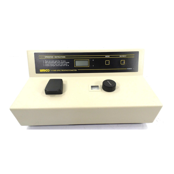
Chemistries, Biochemistry, Food and Beverage Laboratories, Environmental Protection, Water and Waste Water Labs and other fields of quality control. The UNICO 1100 Series spectrophotometers cover the visible wavelength range from 335nm to 1000nm. The analytical grating system has 1200 lines/mm for higher dispersion of the spectrum. - Page 4 Figure 1-1.1 UNICO Model 1100 Spectrophotometer Figure 1-1.2 UNICO Model 1100RS Spectrophotometer 36-4...
-
Page 5: Optical System
1.2 OPTICAL SYSTEM As shown in Figure 1-2 the white light coming from the Halogen Lamp is focused by the collecting lens, pass through the Entrance slit of the Monochromator, through a collimating lens to the Analytical grating where it is dispersed into its spectrum, then through the Exit slit of the monochromator, continues through the Sample compartment and finally to the Photo detector. -
Page 6: Electronic
1.3 ELECTRONIC SYSTEM The photo detector receives the monochromatic light and generates photocurrent. A direct current signal which is proportional to the amount of light energy to the photo detector. The signal is then amplified and processed. The processed signal is sent to the digital display and also to the external outputs 0 Volt to 1 Volt analog output and an RS-232C output. - Page 7 36-7...
- Page 8 36-8...
-
Page 9: Specifications
1.4 SPECIFICATIONS Table 1-1 MODEL 1100 1100RS Wavelength Range 335-1000nm 335-1000nm Spectral Slit Width 20nm 10nm Wavelength Accuracy ±2nm ±2nm Wavelength Readability Stray Radiant Energy ≤0.5%T@340nm &400nm ≤0.5%T@340nm & 400nm Transmittance 0%T to 125%T 0%T to 125.0%T Absorbancy 0A to 2A 0A to 2A Photometric Accuracy ±2.0%T... -
Page 10: Installation
Figure 1- 5 UNICO 1100 SPECTROPHOTOMETER AND NOMENCLATURE 2. INSTALLATION 2.1 The instrument should be installed in a clean environment which is free of corrosive materials, dust and severe vibrations. Furthermore, it should be kept away from any strong electric magnetic fields and high frequency fields. -
Page 11: Maintenance
3. MAINTENANCE 3.1 WORKING ENVIRONMENT The optimum environment for the instruments is as follows 5-35 ° C TEMPERATURE HUMIDITY Install the instrument in a clean non-vibrational area. Avoid direct strong light and air flow. The instrument will give better performance if the power supply stability is at 1% and line frequency less than 1Hz. - Page 12 Normally the UNICO 1100 Series spectrophotometer retains its wavelength calibration indefinitely. However if the instrument receives a severe shock or is abused, use the following methods to check wavelength calibration. Please note that this test requires the UNICO Didymium filter, p/n 1100-110, or the Holmium Oxide filter, p/n 1100-109.
- Page 13 4. Remove the cuvette holder and insert the Didymium filter into it. Place it in the sample compartment and close the lid. 5. Record the Absorbance reading on the digital display. 6. Advance the wavelength setting by 1nm and repeat steps 2 to 5. 7.
- Page 14 Make up N/100 sulfuric acid as the solvent and use part of it to make a solution containing 120 +0.5mg/litre of potassium dichromate. Wash out a square cuvette with solvent, and fill with solvent. Put the cuvette in the adapter into the sample compartment and close the lid. Set the wavelength to 350nm.
- Page 15 Stray Light Check Specification: Less than 0.5%T at 340nm by ASTM E 387 A good indication as to whether the stray light level is within specification may be obtained as follows: Set the wavelength to 340nm. Set the MODE switch to %T. With the square cell adapter in the sample compartment, but no cell, close the lid and press the 0A/100%T button to set the display to 100.0%.
-
Page 16: Operating Procedure Check
Bas i c Ope r a t i o n : Simple operating instructions are printed on the front panel of your UNICO 1100/1100RS. Pr e p a r e t h e spec t r o p h o t o m e t e r Turn on the spectrophotometer by pressing the Power Switch (IO). - Page 17 A n a l y z e Sa m p l e Rinse a second cuvette with a small amount of the sample solution to be tested. Fill the cuvette half full and wipe it. Put the sample cuvette in the sample compartment. Close the lid. Read the %Transmittance or Absorbance from the digital readout window.
- Page 18 8. With the standard concentration set, determine the concentration values of samples with unknown concentration by inserting the sample cuvette into the sample compartment and reading the value direct from the display. 9. To read the value of the multiplier used to convert Abs to Concentration, after measuring all the samples, change the Mode to Factor (F) and read the multiplier from the display.
- Page 19 Mo d e l 11 0 0 Spec t r o p h o t o m e t e r : Mode Indicator: Allows the operator to know the measurement mode currently in use (%Transmittance, Absorbance) . MODE Button: Switches between %Transmittance and Absorbance operating modes at any time of measurement.
- Page 20 Mo d e l 11 0 0 R S Spec t r o p h o t o m e t e r : Mode Indicator: Allows the operator to know the measurement mode currently in use (%Transmittance, Absorbance). MODE Button: Switches between %Transmittance and Absorbance operating modes at any time of measurement.
- Page 21 Wavelength Control Knob (WAVELENGTH): Selects desired wavelength in nanometers (nm). Wavelength Readout Window: Displays desired wavelength. 36-21...
-
Page 22: Troubleshooting
4.3 TROUBLE SHOOTING #1 Problem:Turn on, No display Is 115V or 230v Pilot light Power on? Line power on Display on? Switch function? Replace R13-69A switch Check if LCD display and wiring OK? PC power Function? Replace PC power A:Replace CPU board B:Sloving wiring problem or Check the +8V and replace socket A2,A3... -
Page 23: Troubleshooting
TROUBLE SHOOTING #2 Problem:Instrument is on, Display 0.000(%T)or 1---(A) Halogen lamp on? Check lamp OK? Replace lamp Anything in sample Check output of lamp comparment Power supply, is it blocking the light? Between +1.6V to 6.2V Remove it Refer Fig.5.3 to check W lamp power supply Is cell holder and Cuvette in position? - Page 24 TROUBLE SHOOTING #3 Problem:Turn on,put in cell holder and cuvette ,display “<<10.0”, press “100%T”,display not change Is the position of halogen lamp right? Adjust the position of halogen lamp,put a piece of white retangle paper into Is the light road out of sample comparment(open the position the shutter),can see a...
- Page 25 TROUBLE SHOOTING #4 Problem: Instrument on Display “1— — —”(T%) or show negative at absorbance sample compartment cover closed? Close the sample compartment Is cell holder and cuvette in positior Shutter working Put the cell holder and cuvette into the sample compatrment Repair shutter assembly Press “100%”,after display “100.0”...
- Page 26 TROUBLE SHOOTING #5 Problem: Instrument on → “100.0” display not stable (T) Enough warm up time? Warm up at least 20 min Groounding OK? Improuve grounding Power supply OK Get rid of possible interference facters After changed wavelength stable time full After 5 min press “100%”...
- Page 27 TROUBLE SHOOTING #6 Problem:measuring recelts incorrect(not stable,repeatability,etc) Is sample preparation adjust right? a use right procedures to b prepare samples c make sure no bubble in sample Is sample preparation d test only after sample stability Installed correctly? e select right wavelength get rid of possible interference factors Are cuvettes used matched?
-
Page 28: Drawing And Diagram
5.Drawing&diagram PCB Arrangement of Power Supply 1. Check if the monochromator light passed onto the detector at right angle and right position (area) of the detector if not, adjust 5.1.1 Circuit Diagram of Power Supply 2. Amplifier output voltage (static): 20mV-30mV, put black body to prevent the light from light way, refer to Fig5.3 to adjust the PCB Arrangement of CPU potentiometer W to change the output voltage to... - Page 29 36-29...
- Page 30 36-30...
- Page 31 36-31...
- Page 32 36-32...
- Page 33 36-33...
- Page 34 36-34...
-
Page 35: Schematic Loyout
6 Schematic Layout PART LIST OF UNICO 1100 SERIES SPECTROPHOTOMETERS Number Description On/Off Switch Pc-power Power socket Wavelength disc Wavelength indicator Part of grating Monochromator Sample compartment Filter drive strap Filter commutation cam Amplifier dark box Amplifier Halogen lamp Junction-box... - Page 36 36-36...
Need help?
Do you have a question about the UNICO 1100 and is the answer not in the manual?
Questions and answers